

Abstract
In this paper, we propose multiple modalities based on laser speckle correlation and image registration to enhance the visibility of the fundus without a scanning interferometric scenario, resulting in robustness against intra frame noises induced by inevitable movement. The experimental results showed, with the features from laser speckle contrast imaging (LSCI), that the quality of images obtained using a conventional imaging system could be enhanced. Moreover, by applying the image registration process, we successfully eliminated the inter frame blurring caused by eye movements in an in vivo experiment. The concept was proven when the image contrast of a vascular feature was improved by 1.00×–2.75×.
Export citation and abstract BibTeX RIS
1. Introduction
Ocular diseases have increasingly become a concern owing to the higher frequency of heavy exposure of the eyes to various electronic devices. Pioneering research has revealed that the abnormality of retinal vasculature is a significant early indicator of ocular diseases, such as diabetic retinopathy and age-related macular degeneration.1) As a consequence, several modalities based on two-dimensional fundus photography or three-dimensional optical coherence tomography (OCT) were developed for functional retinal imaging.1,2) With the aid of these devices, the features of abnormalities or early symptoms could be diagnosed through clinical examination. Despite the excellent performance provided by these instruments, the bulky form factor and delicate setup restricted their flexibility and convenience in many possible applications such as portable usage.
In this study, we attempted to improve image quality by introducing an extra laser illumination into conventional fundus photography. With the support of multiple modalities, the proposed system can reconstruct higher-quality images by laser speckle contrast imaging (LSCI).3–5) Unlike the principle of OCT, the idea of this proposed method is to enhance the image quality without a scanning interferometric scenario, resulting in robustness against inevitable intra frame movements or perturbations in portable usage. Preliminary experimental results validated the feasibility of the proposed system, which achieved apparent improvement in the image contrast of blood vessels with the help of LSCI. On the other hand, by integrating the process of image registration, this device became robust against minute inter frame movements induced by the autonomic nervous system or unstable environments.6–9)
2. Experimental methods
A fundus system, composed of illumination and imaging parts, acquires the retinal images through the tiny pupil of the eye. To overview the system comprehensively, in this section, we first elucidate the main parameters of the optical design, and choose the appropriate operational conditions. The technique of LSCI is then explained, aiming to reveal the greater clarity of retinal images obtained by this technique than by common microscopy systems.3–5)
2.1. Optical design of fundus photography system
The retina is located on the focal plane of the crystalline lens of the eyeball; thus, the retinal image is relayed to the conjugate plane (usually at infinity) of the crystalline lens. Typically, we place the lens L1 in front of the pupil to generate a reverse image at the intermediate image plane, as shown in Fig. 1. This reverse image is further magnified by L2 to produce an image on the sensor plane.
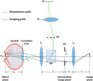
Fig. 1. Schematic diagram of the optics of fundus photography. LS, light source; CL, collector lens; AD, aperture diaphragm; BS, beam splitter; FD, field diaphragm; Ln, lenses. In our experiment, the focal lengths of the lenses are 30 and 100 mm (f1 = 300 mm and f2 = 100 mm).
Download figure:
Standard image High-resolution imageTo evaluate the imaging performance (marked by a solid line in Fig. 1), the imaging process is usually divided into two steps. The first step involves the optical path from the retina to the intermediate image plane, including the crystalline lens and a single lens L1. The two lenses (crystalline lens and L1) are respectively regarded as the objective and tube lens so that this optical train is equivalent to the mechanism of infinity-corrected microscopes.10) Through this optical train, light rays emanating from either the central region or the periphery of the retina are gathered by the crystalline lens to produce parallel bundles of rays since the location of the retina (object plane) was at the front focal plane of the crystalline lens. The parallel bundle of light rays projected either along the optical axis or with oblique angles to the singlet L1, is dependent on the retinal position. The lights gathered by L1 are then focused at its focal plane (the intermediate image plane) to form a reverse image of the retina. Therefore, the magnification of this imaging step M1 is calculated as the ratio of the focal length of L1 (f1), to the focal length of the crystalline lens (fCL), as shown in
On the other hand, since the imaging process is equivalent to the telecentric system in the space of an object, the field of view (FOV) is constrained by a field diaphragm located at the intermediate image plane. Their relationship could be expressed as

where D is the diameter of the field diaphragm and DObj is the corresponding diameter of the FOV at the object plane, as shown in Fig. 1. Equation (2) implies that the FOV has a reciprocal relationship with f1. The maximum FOV at the object space is achieved when the diameter of the field diaphragm matches the diameter of L1. Nevertheless, it is necessary to constrain the FOV via the field diaphragm to satisfy the paraxial approximation and alleviate the aberrations.
The second step involves the path from the intermediate image to the actual image plane (it can be an observer's eye or an imaging sensor). The magnification of this imaging step, M2, can be simply determined by the magnification of L2. As a result, the image size can be calculated as M2D. The physical size of the image captured by the image sensor might sometimes be less than this result owing to the limitation of the sensor format. After considering both steps, we can attain the magnification M of the entire retinal imaging system as
where the quantities p and q represent the object distance (from the intermediate image plane to the principal plane of L2) and the image distance (from the principal plane of L2 to the image plane).
To accomplish fundus photography, it is necessary to provide extra illumination with appropriate optics to light up the vitreous chamber. The most popular setup is based on the concept of Köhler illumination for eliminating the source image at the object plane.11) On the other hand, in order to eliminate glare reflection from the cornea, other specific requirements for the design of the light source (e.g., source shape and location) are considered.
Typically, the illumination optics for fundus photography requires at least three important elements, namely, a light source, a collector lens, and a condenser (the crystalline lens), as shown in Fig. 1. For simplicity, only the lights emanating from the periphery of the light source are illustrated (indicated by the green dash line in Fig. 1). The bundle of light rays transmitted from the collector lens produces a source image at the aperture diaphragm, which was then gathered by L1 to illuminate onto the retina (object plane). This design prevents the production of a conjugate image of the light source at the object plane, which severely degrades the image quality. However, because the illumination optics share a common path with the imaging optics, the conjugate image of the aperture diaphragm at the pupil and the glare reflections from the cornea are likely gathered by the imaging optics. Compared with these signals, the back reflections from the retina are much weaker.12,13) To minimize the glare reflections from the cornea, the common approach is to utilize an aperture diaphragm with an annular shape or a light source for off-axis illumination.14–16) The rule of thumb is to maximize the use of the pupil with high efficiency, that is, the conjugate image of the annular light source is imaged at the outer portion of the pupil, as the illumination path. This implies that only the light ray bundle emanating from the central region of the pupil is captured by the imaging optics once the field diaphragm has been properly adjusted.
According to a previous work, the imaging system could achieve the largest illumination efficiency for acquiring maximum reflected power when the area of the illuminating annulus was equal to the area of the imaging pupil.15) Nevertheless, this inference was based on an aberration-free system and efficiency might be deteriorated by any aberration in optical elements or the oculus. For example, the geometric shape and location of the illuminating annulus on the pupil may be significantly distorted by the aberrations of optical elements, resulting in undesired back reflections from the cornea. Such aberrations could be eliminated effectively by increasing the inner radius of the illuminating annulus but sacrificing illumination efficiency. On the other hand, ocular aberrations also affect the image quality of fundus photography because the point spread function of the crystalline lens is degraded.17–23) Therefore, the optimal pupil diameter of the oculus was suggested to be 2 mm in most practical devices in order to minimize the ocular aberrations.15,16,23) Although a smaller imaging pupil may alleviate the image degradation to maintain the image quality, the resolving power is simultaneously reduced owing to the increase in f-number. To increase the resolving power of the optical system, several approaches had been proposed, such as wavefront correction with the adaptive optics system,24,25) iterative shift-and-add technique,26) image deconvolution via estimation of the point spread function,27,28) and impedance matching.29) Recently, a binocular fundus camera with a larger pupil diameter has also been developed.30) These methods aimed to improve the image quality via post-processing or reducing the f-number, and have successfully achieved a cellular-level resolution. Nevertheless, additional perturbations induced by the movement of the testing sample or the device itself might increase computational complexity. Rather than portable usage,31) this kind of device is more suitable for stationary usage, providing great potential for further improvement.
2.2. Laser speckle contrast imaging
When a rough surface is illuminated by a coherent light source, a large number of interference dots called speckles are generated owing to the severe scattering phenomenon. Although these interference dots seemed to be annoying in most holographic purposes, many studies have revealed that high-order information can be extracted from an underlying randomly distributed pattern.3–5) By analyzing the statistical properties of such an interference phenomenon, the speckle contrast (K) of a speckle pattern could be defined as

where the angle brackets 〈·〉 denote the ensemble average so that 〈I〉 is the first moment (mean) and σI is its second moment (standard deviation) of a selected window.3) The speckle contrast is widely used as a trait to characterize fluid dynamics. From the definition of K, local regions without vessels are expected to have a lower speckle contrast K than those with vessels since any moving particle might lead to a blurred speckle pattern during one exposure of an imaging sensor. This characteristic enabled us to reconstruct a contrast image to monitor the blood flow in tissues.4,5,9,32)
Typically, there are two approaches to calculating the speckle contrast K, spatial and temporal approaches, using different methods of statistical analysis,4) as shown in Fig. 2. The first approach requires the pixel values of N frames to calculate the speckle contrast,  , of every specific point
  ; this approach is known as laser speckle temporal contrast analysis (LSTCA). This implies that it is necessary to take N exposures into consideration to obtain one contrast image, which is a challenge in real-time monitoring, especially in cases of low sample irradiance such as in fundus photography. An alternative way is to calculate the speckle contrast using a kernel, h, which is obtained with a snapshot. This is called laser speckle spatial contrast analysis (LSSCA). LSSCA has a superior real-time response to LSTCA with the sacrifice of spatial resolution. Either spatial or temporal resolution would be considered as a trade-off. For LSSCA, the kernel size predominately degrades the spatial resolution of images. The statistical characteristics of local speckle images sampled on the basis of kernel h are also affected by kernel size owing to insufficient sampling.33) The kernel size in practical LSCI-related devices is commonly 5 × 5 or 7 × 7 in order to maintain sufficient sampling, which severely compromises the spatial resolution of contrast images.34) Moreover, previous research carried out by Cheng et al. also indicated that the performance of LSSCA is susceptible to stationary speckles induced by static tissues or other scattered media in the optical path.35) On the other hand, for LSTCA, the first critical issue is to guarantee that the speckle patterns acquired by the same pixel are statistically independent.3) The condition usually holds in most coherent sources since the coherence time is usually much less than the exposure time Δt. The second issue is the dependence of the exposure time on the flow velocity of an object. For example, a short exposure time enables us to acquire clear speckle patterns in both regions with and without blood vessels. In contrast, a long exposure time might result in blurry speckle patterns in the region with blood vessels since the lights are scattered by moving particles, allowing us to reconstruct a contrast image by LSCI. For the flow velocity on the order of 7–10 cm/s, the suggested exposure time is from several milliseconds to dozens of milliseconds.4,5,35)

Fig. 2. Illustration of the temporal and spatial analyses for speckle contrast calculation. The calculation of temporal speckle contrast  (green) requires N frames, on the other hand, the calculation of spatial speckle contrast
  (red) only considers the pixels within kernel h of one frame.
Download figure:
Standard image High-resolution imageSince there exists a fundamental tradeoff between the spatial and temporal resolutions, in this work, we chose LSTCA to preserve the highest possible spatial resolution. The image quality was improved using correlated laser speckles.
3. Results and discussion
On the basis of the setup in Fig. 1, fundus photography with LSCI for a live animal (rabbit) was conducted. The light sources were a diode laser (Thorlabs CPS532-32) and an LED light source with a bandpass filter (530 ± 5 nm, Andover 530FS10) to be consistent with the central wavelength of the laser. The effective focal lengths of the lenses were f1 = 30 mm and f2 = 100 mm. According to Eqs. (1) and (3), the effective magnification of the first imaging step was M1 = 0.83 for the rabbit.36) The effective magnification of the second imaging step, M2, was 1.81. Hence, the total magnification M was 1.5× in the following experiment, which corresponded to a 3 × 3 mm2 area in the object space complying with the imaging sensor with the 1/2-in. sensor format (FLIR FL3-U3-13Y3M-C). The exposure time Δt was 40 ms in the following experiments of fundus photography and LSCI. The frame number N was 40 in the LSCI experiment.
The fundus images obtained under incoherent and coherent illuminations, and the corresponding LSCI image from a live rabbit are shown in Fig. 3. The vessels obtained by a conventional imaging technique (enclosed in the red frame) were barely distinguishable, as shown in Figs. 3(a) and 3(b). However, by combining LSCI with conventional fundus photography, the features of the vessels were enhanced, as shown in Fig. 3(c). To assess the quality of the image obtained by LSCI, we applied the average image contrast C as a subjective merit for human interpretation. The definition of image contrast is expressed as

where Imax and Imin are the peak and valley values of the intensity profile around the vessels. The average contrasts of the fundus image within the red frame were approximately 0.15 with incoherent illumination and 0.08 with coherent illumination. On the other hand, as observed in Fig. 3(c), significant improvements were found, where average contrast was 0.30, corresponding to the 1.00×–2.75× improvement compared with the original fundus images. As a result, the concept of the proposed method was proved to reveal more details of retinal images using a modality without the need for scanning interferometry, which is expected to be useful for doctors in clinical examinations.
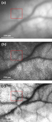
Fig. 3. Images of rabbit retina with (a) incoherent illumination, (b) coherent illumination, and (c) LSCI image. Vessels enclosed by the red frame are barely distinguishable in images obtained using a conventional fundus system, but are enhanced when their images are obtained with the help of LSCI.
Download figure:
Standard image High-resolution imageIn addition, the system performance for a dynamic object requires further consideration for in vivo measurements. Since the LSTCA requires multiple exposures to reconstruct a single image, it implies that any inter frame movement during the exposure would lead to a blurry image. In addition, inter frame motions also affect the precision of feature points. In this rabbit experiment, the exposure time Δt of each exposure was 40 ms, which means that this system required 1.6 s to complete the entire image acquisition process (N = 40). Any inter frame movement caused by the test subject, user, or the environment led to undesired differences between frames and distorted the corresponding results of LSTCA. Consequently, a blurred image would be obtained, as shown in Fig. 4(a). This blurring occurred in most in vivo measurements regardless of whether the test sample was immobilized or not.
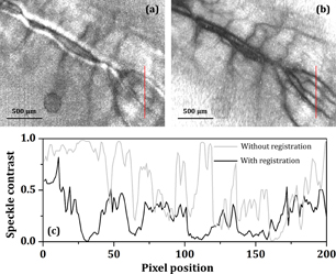
Fig. 4. Images obtained by LSCI (a) without image registration and (b) with image registration process. (c) Speckle contrast of (a) and (b) along the red lines.
Download figure:
Standard image High-resolution image
In order to overcome the problem caused by inter frame motions, we conducted a post-image process, where multiple frames were realigned to a common image grid.9) This task was accomplished using a Fourier-transform-based technique, called phase correlation,6) where the idea of phase correlation is based on the shift and autocorrelation theorems of Fourier transform.37) The relative translation between two similar objects would induce an additional phase difference in their Fourier spectra, proportional to the amount of translation. Therefore, the relative translation could be estimated by calculating the cross-power spectra among individual frames. The phase correlation method is robust and efficient for estimating translations even for translations on the order of subpixels.7,8) Using phase correlation, we were able to realign raw images, that is the raw images for reconstructing Fig. 4(a), and synthesized a better LSCI image, as shown in Fig. 4(b). The profiles of the speckle contrast along the red line of both images are plotted in Fig. 4(c). An improvement of 1.88× was achieved (average image contrast from 0.31 to 0.88) by image registration. This improvement indicates that the proposed system has the capability to restore blurry images and is robust against the movements induced by the autonomic nervous system or other minute perturbations.
4. Conclusions
We reviewed two primary design concepts of fundus photography, the imaging and illumination optics. Basically, the mechanism of fundus photography is equivalent to that of microscopy optics once we place a singlet in front of the eye. The combination of this singlet and the crystalline lens could be regarded as an objective lens, which gathers the light rays emanating from the retina and produces an image at its image plane. In this manner, optical parameters of this system, such as the FOV and magnification, could be easily derived, as shown by Eqs. (2) and (3). On the other hand, in order to eliminate undesired glare reflection from the cornea, an off-axis or annulus illumination is applied through the periphery of the pupil, sacrificing resolving power and the corresponding image quality owing to the reduced effective pupil size for imaging purpose.
By applying the LSCI technique as an augmented modality, we successfully enhanced the contrast of the retinal image. Since the LSCI technique is based on a non scanning interferometric scenario, the multi modality scheme can reduce any undesired intra frame perturbation and increase the flexibility for portable applications. The experimental results indicate that significant improvement could be achieved by using correlated laser speckles (1.00×–2.75× improvement of the average image contrast). On the other hand, with image registration, this system could improve blurry images caused by inter frame motion (1.88× improvement of the average image contrast), which showed that this system is robust against minute inter frame movements such as vibrations induced by the autonomic nervous system, users, or testing environment. As a result, the proposed fundus photography with subpixel registration of correlated laser speckle images was demonstrated to improve the performance of the fundus camera making it useful for clinical examinations.
Acknowledgments
This work was financially supported by the Ministry of Science and Technology (MOST) of the Taiwan government under grant No. 105-2622-E-009-006-CC2. The authors would like to thank Medimaging Integrated Solution Inc. (MiiS) for instrument and technical support. The authors would also like to thank Dr. Yu-Chien Chung and Dr. Shih-Jen Chen for their medical advice.