

Abstract
We report a novel low-power nitriding technique by utilizing a 2.45 GHz microwave-excited nitrogen radical flow system. Nitrogen plasma was produced at the nozzle with dimensions of 50 × 0.5 mm2 and blown onto the surface of a target substrate. A titanium substrate has been used as a target plate since it is easy to visualize a nitriding effect. The titanium substrate was treated under the conditions of 60 W microwave power, 20 Torr of nitrogen gas pressure, and a plate temperature of ∼800 °C. As a result, we have succeeded in nitriding of the titanium substrate in a quasi-atmospheric region of 20 Torr and of a very low power of 60 W with the hardness kept high, which is almost the same as the hardness processed by conventional nitriding methods.
Export citation and abstract BibTeX RIS
1. Introduction
The nitriding process is one of surface modification techniques used to improve sliding wear resistance and fatigue strength.1–5) The nitriding process has been widely used for parts of mechanical machines, medical products, and internal combustion engines.6–8) In general, gas nitriding and salt bath nitriding have been used as conventional nitriding techniques.9–13) In the salt bath nitriding process, the materials are immersed in a salt bath containing 60–70% by weight of NaCN, 30–40% of KCN, and few percent of Na2CO3 and NaCNO.14) Although salt bath nitriding allows us to decrease processing time, this process causes severe environment problems due to the waste salts, rinse water, and difficulty in controlling the chemical reactivity of the bath.15) On the other hand, in gas nitriding process, materials are treated in ammonia atmosphere for 10–120 h of processing time. The gas nitriding process can treat materials without environmental problems due to waste salts. However, gas nitriding has issues as follows: limitation of processed material species, long processing time to achieve sufficient hardness, and huge amounts of exhaust gas.16)
Plasma nitriding is also a surface modification technique for materials. In a conventional plasma nitriding technique, a substrate is treated in a process chamber filled with nitrogen gas or nitrogen-based gas, and DC bias-voltage is applied between the substrate and the chamber to produce glow discharge plasma on the surface of the substrate.17–20) In this technique, radical nitrogen molecules and energized nitrogen ions accelerated by the applied bias-voltage actively bombard the substrate to produce a nitride surface effectively. Therefore, plasma nitriding has succeeded in reducing process time and exhaust of process gas compared with the bath salt and gas nitriding systems. However, the plasma nitriding technique has not been widely used compared with the gas nitride technique since the plasma nitriding technique has remained technical issues arising from the applied bias voltage and economic issues such as increases in cost and energy consumption accompanied by the increase in a target size.
Recently, plasmas produced in the high-pressure region have been attracted in various fields. An atmospheric pressure plasma has been interested as a plasma nitriding process to solve the economic and technological problems of plasma nitriding described above.21) Plasma treatment in the atmospheric-pressure region allows us to simplify the system configuration and working process because of the absence of the high vacuum system and increase in the total number of reactive nitrogen particles. On the other hand, nitrogen plasma produced at quasi-atmospheric pressures of 10–100 Torr has also been focused on metal organic chemical vapor deposition (MOCVD) process as a nitrogen radical source.22–24) In particular, low-temperature plasma in the high-pressure range does not induce overheating of target materials, namely, supply of the radical nitrogen will be achieved for InGaN processing under 700 °C to suppress the sublimation of the indium material from the substrate. Although high-pressure plasma nitriding has attractive features, it is difficult to sustain stably low-temperature plasma flow that contains sufficient amounts of reactive species even when using a low power consumption system.
A microwave-excited plasma source25) has successfully produced an atmospheric pressure plasma flow that contains CH4, Ar, and H2, at a frequency of 2.45 GHz and a microwave power of 60 W. In this study, the microwave excited plasma source has been proposed for application in a new plasma nitriding system. Since this nitriding system does not require applying a bias voltage to the target alloy and highly energy consumption for plasma production, this nitriding system potentially solves the above technical problems caused by the applied bias voltage. In addition, plasma nitriding with low power consumption enables to realize application for the MOCVD systems.
Recently, we have studied radical production by optical emission spectroscopy (OES) measurement, and we have also conducted plasma nitriding of a titanium substrate using our new plasma nitriding system. In this paper, we present the preliminary experimental results on nitrogen plasma characteristics obtained by OES measurement, surface analysis by Raman spectra measurement, X-ray diffraction (XRD) measurement, Martens hardness measurement, and scanning electron microscope (SEM) of the treated nitriding surface of titanium.
2. Experimental methods
Nitrogen plasma was produced using the microwave-excited plasma source. The plasma source consisted of a sub miniature type A (SMA) connector, a dielectric body, a bottom metal plate, and micro-strip lines.25) Microwaves with a frequency of 2.45 GHz and a power of up to 200 W were introduced to the plasma device through a coaxial cable and a SMA-connector to excite plasmas at the nozzle exit. A working gas was fed into gas feeding lines in the dielectric body, and the gas was ionized around the nozzle at which a strong electric field was induced by the propagated microwaves. Consequently, the microwave plasma source forms a 50 × 0.5 mm2 area of nitrogen plasma at the nozzle, and the nitrogen plasma is blown from the nozzle. The working gas was pure nitrogen (99.999%) flowing at a rate of 0.5–6.0 slm in this study.
The OES measurement was carried out to determine the characteristics of nitrogen plasma. Figure 1 shows schematic views of the experimental setups for the (a) OES measurement and (b) plasma nitriding process. As shown in Fig. 1(a), the spectroscopic system consists of a collimator lens, an optical fiber, and a grating spectrometer of BLUEWAVE (Steller Net) with a measureable wavelength range of 200–1050 nm, a groove density of 600 grooves/mm, and a wavelength resolution of 0.5 nm. OES was performed outside the nozzle, and the convex lens with a focal length of 500 mm, was installed in 500 mm from the center of the slit nozzle.

Download figure:
Standard image High-resolution image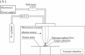
Fig. 1. Schematic drawing of the experimental setup: (a) configuration of optical emission spectroscopy and (b) plasma nitriding system.
Download figure:
Standard image High-resolution imageThe microwave-excited plasma source was applied to plasma nitriding process, and the plasma source was installed in a plasma nitriding system that consists of a metallic chamber, a vacuum system, and a heating plate, as shown in Fig. 1(b). In this study, pure titanium alloy was employed as the target material to visualize the nitriding effect whether titanium nitride is produced or not. During the plasma nitriding process, the processing parameter such as microwave power, atmospheric pressure, gas flowing rate, and temperature of the target plate were kept at each arbitrary values.
Figure 2 shows a photograph of the newly developed plasma nitriding device and the nitrogen plasma produced, taken from the (a) front and (b) oblique directions. The plasma source was installed in a vacuum chamber. A target substrate was set on the heater plate under the plasma source. As shown in Fig. 2, the developed plasma nitriding system actively splays nitrogen plasmas without the need for an applied a negative bias voltage on the substrate to bombard the nitrogen ions and molecules.

Download figure:
Standard image High-resolution image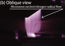
Fig. 2. (Color) Photographs of nitrogen radical flow: (a) frontal view and (b) oblique view.
Download figure:
Standard image High-resolution image3. Results and discussion
3.1. OES measurement of formed nitrogen plasma
OES measurement was performed to clarify the plasma characteristics of radical production related to nitrogen gas flow rate and chamber pressure. Figure 3 shows the emission profiles at gas flow rates of 0.2, 0.5, 1.0, and 2.0 slm. In this measurement, the chamber pressure was kept at 30 Torr, and the input microwave power was 50 W. The emission of the second positive system (C3Πu–B3Πg) is shown in Fig. 3(a), and the emission of the first positive system (B3Πg–A3Σu+) is shown in Fig. 3(b). Strong emission of the second positive system was observed in all cases, as shown in Fig. 3(a) compared with the emission of the first positive system. Since the energy state of the second positive system is higher than that of the first positive system,26) the results indicate that highly energetic radicals of the nitrogen molecule were effectively generated even at a relatively high pressure of 30 Torr, and the energy consumption of 50 W is only required to form a nitrogen radical flow using our developed plasma source. Furthermore, the emission intensity of second positive system increased with increasing gas flow rate. On the other hand, the emission intensity of the first positive system decreased with increasing the gas flow rate, as shown in Fig. 3(b). The results shown in Figs. 3(a) and 3(b) indicate that highly energetic nitrogen radicals are effectively enhanced to increase gas flow rate.

Fig. 3. (Color) Emission profiles of nitrogen radical flow at various nitrogen gas flow rates in the range of (a) second positive system and (b) first positive system.
Download figure:
Standard image High-resolution imageMoreover, the emission profiles at different chamber pressures of 5, 10, 25, and 30 Torr are shown in Figs. 4(a) and 4(b). In this measurement, the gas flow rate was kept at 0.6 slm, and the input microwave power was 50 W. The emission of the second positive system was dominant, and the emission intensity increased with increasing chamber pressure. It is considered that the increase in chamber pressure enhances collisions between the energized electrons generated at the nozzle of the plasma source and the pre-existing nitrogen molecules, and the population of radical nitrogen molecules such as the second positive state of nitrogen is consequently increased by the collision. In consequence, the emission of nitrogen atoms has not been observed in the microwave excited nitrogen radical flow generated under high-pressure condition. The reactive species of nitrogen are generated in the vicinity of the exit slit of the plasma source and flow into the high-pressure region. The emission of the first positive system of such a radical flow results from the three-body recombination of nitrogen atoms.27) Therefore, atomic nitrogen produced by energetic electrons at the exit slit of the plasma source is immediately changed to a reactive nitrogen molecule by the collisions with other species such as nitrogen atoms and molecules. As shown in Figs. 3 and 4, the production efficiency of radical nitrogen molecules increases, as the chamber pressure and gas flow rate, and the emission of nitrogen molecules increase.

Fig. 4. (Color) Emission profiles of nitrogen radical flow at various chamber pressures in the range of (a) second positive system and (b) first positive system.
Download figure:
Standard image High-resolution image3.2. Plasma nitriding of titanium substrate
Plasma nitriding was performed under the condition described in Table I, which shows the following plasma nitriding parameters: microwave power, gas flowing rate, nitriding temperature, treatment time, Ld (distance between the device nozzle and the surface of substrate), and chamber pressure. As shown in Fig. 2, the plasma source forms a zonal nitrogen radical flow, and the radical flow is blown down from the nozzle of plasma source to titanium substrate.
Table I. Treatment conditions of plasma nitriding.
| Microwave power (W) | 60 |
| Gas flow rate (slm) | 1 |
| Treatment temperature (°C) | 800 |
| Treatment time (h) | 1 |
| Ld (mm) | 3 |
| Chamber pressure (Torr) | 20 |
Figure 5 shows photographs of the substrates (a) without plasma nitriding and (b) with plasma nitriding. On the plasma nitriding substrate, we can identify that the surface color is metallic gold, as shown in Fig. 5(b). Since titanium nitride is typically metallic gold, these color variations observed after plasma nitriding indicates the presence of titanium nitride.

Download figure:
Standard image High-resolution image
Fig. 5. (Color) Photographs of substrate surface (a) without plasma nitriding and (b) with plasma nitriding.
Download figure:
Standard image High-resolution imageIn addition, the Raman spectra from the two substrates of with and without plasma nitriding were measured using a Renishow spectrometer (inVia Raman microscope), as shown in Fig. 6. The bands at 200, 330, and 550 cm−1 were observed and are characteristics of the first-order scattering of titanium nitride.28) The vibrations of heavier Ti ions produce the lower-frequency peaks around 200 and 330 cm−1, and the vibrations of lighter N ions produce the higher-frequency peak at around 550 cm−1. Thus, the peak appearing around 550 cm−1 is also the evidence for the presence of titanium nitride on the surface of the substrate with plasma treatment.
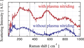
Fig. 6. Raman spectra profiles obtained from substrate surface without plasma nitriding (blue line) and with plasma nitriding (red line). Dashed lines indicate bands of Raman scattering for titanium nitride.
Download figure:
Standard image High-resolution imageXRD measurement of the plasma nitriding alloy surface was also carried out using Rigaku MiniFlex, which uses Cu Kα lines as its source of X-rays. The results of XRD of the plasma-treated alloy are shown in Fig. 7. Peaks corresponding to Ti, Ti2N, and TiN were observed in the XRD profile of the plasma nitriding alloy. The peak of Ti2N is the predominant signal except for the peak of α-Ti, and the diffraction peaks of TiN crystalline appeared on the alloy surface. Since the alloy surface showed a change in color from gray to gold after irradiation of a nitrogen radical flow, as shown in Fig. 5, the obtained diffraction pattern is consistent with the results of surface color visualization and Raman scattering measurement.
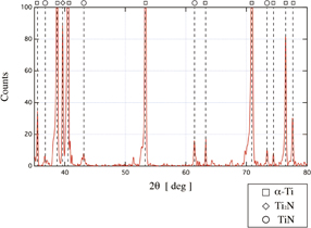
Fig. 7. XRD profiles obtained from substrate surface with plasma nitriding. Empty squares, diamonds, and circles indicate α-Ti, Ti2N, and TiN, respectively.
Download figure:
Standard image High-resolution imageTo understand nitriding information along the depth from the surface, SEM measurement was conducted. Figure 8 shows a cross-sectional image of nitride titanium alloy measured by SEM. The nitride layer appeared on the surface of the titanium alloy with a depth of almost 2 µm. Here, the nitrided titanium was cut to expose its cross-section at first, and resin embedding planarization was conducted. In addition to SEM measurement, the Martens hardness values of the produced titanium nitride surface and titanium surface without plasma nitriding were measured using a nano-indentation tester (Elionix ENT1100a). The obtained Martens hardness profile is shown in Fig. 9. The x is defined as the distance from the center of the area treated with nitrogen radical flow. After plasma nitriding, 16 GPa of Martens hardness on the surface was achieved at x = 0 mm. As indicated in Fig. 9, the hardness decreased with x, because the nitrogen radical flow was blown at x = 0 cm. Note that the substrate rotation system to irradiate the radial flow uniformly was not operated in this experimental series. A Martens hardness of 11.4 GPa for the substrate without plasma nitriding was obtained at x = 0 mm as a reference, and this hardness is smaller than that for the substrate with plasma nitriding. Therefore, we obtained a titanium nitride surface with up to a Martens hardness of 16 GPa at a power of 60 W under relatively high pressure of 20 Torr. This hardness obtained using this method is almost the same as that obtained using conventional nitriding methods. In general, a conventional ion nitriding system requires high voltage and power to sustain nitrogen glow plasmas stably with the treated volumes maintained over the quasi-atmospheric pressure region of 10–100 Torr. However, a high voltage can easily induce arc discharges in a small gap existing in the process chamber. In contrast, this proposed method can sustain nitrogen plasma stably at a very low microwave power of 60 W without inducing an arc discharge, which corresponds to a power density of 3 W/cm2 even at 20 Torr, although the power density is the same or one-order higher than that used in conventional procedures.29–31)
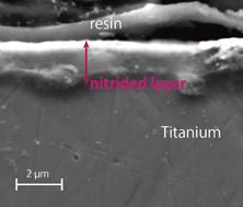
Fig. 8. (Color) Cross-sectional observation of the nitrided titanium measured by SEM.
Download figure:
Standard image High-resolution image
Fig. 9. (Color) Martens hardness profile of the titanium nitride surface measured using a nano-indentation tester.
Download figure:
Standard image High-resolution image
4. Conclusions
Titanium substrates were successfully nitrided at a relatively high pressure of 20 Torr, by a novel plasma nitriding technique using a 2.45 GHz microwave excited radical flow system. After the plasma nitriding, the surface color of the substrate varied from gray to gold. Raman spectra measurement and XRD measurement also showed the presence of titanium nitride on the substrate surface. Moreover, we evaluated Martens hardness of the achieved titanium substrates. As a result, the obtained Martens hardness of the surface was up to 16 GPa, which is comparable to those of the substrates processed by conventional nitriding techniques. By SEM measurement, it was confirmed that the micrometer-order depth of nitriding was achieved. This technique developed enables the generation of a radical nitrogen flow under the conditions of a power consumption of less than 100 W and relatively high pressures (10–100 Torr).