

Abstract
A probe method to measure the diffusion coefficient and the ion temperature in the edge plasma is proposed. The probe is constructed as an asymmetric double probe, where one electrode is sensitive to the direction of magnetic field while the other is insensitive to it. The ratio of ion saturation currents to two electrodes is used to determine the diffusion coefficient from which the ion temperature is estimated. The saturation currents are calculated by taking the anisotropic diffusion to the probe into account. The present probe method is applicable in the edge plasma even with such a complicated magnetic field as that in helical devices.
Export citation and abstract BibTeX RIS
Several probe methods have been developed to measure the ion temperature in fusion plasmas.1–5) In the edges of these plasmas, the ion temperature Ti has been found to exceed the electron temperature Te in tokamaks such as DITE,6) TEXTOR,7) and JFT-2M.8) In the plasmas with Ti > Te, the effect of the presheath is small so the ions reach the probe with almost the thermal velocity. Furthermore, in the edge plasma, the movement of ions cannot always be treated as being completely collisionless. Since the magnetic field is strong, the diffusion becomes strongly anisotropic. In view of these facts, in this paper, the diffusion equation is applied under the condition of anisotropic flow due to a strong magnetic field.
Heretofore, the diffusion and thermal diffusion coefficients have been estimated from the e-folding length of the ion temperature and density.9) The objective of this paper is to present a method to obtain the diffusion coefficient directly. The ion temperature can be estimated from the diffusion coefficient. The present probe method will be useful in high-density and high-temperature plasmas.
We assume that the double probe is composed of two electrodes: a disk and a sphere with radius a. We take the magnetic field B along the z-axis (cf. Fig. 1). The normal N of the disk at the center O pretends B by angle φ and the y-axis is perpendicular to the z-axis. Then, the x-axis can be automatically defined. The coordinates for the sphere are taken similarly.
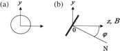
Fig. 1. Double probe consisting of (a) spherical and (b) disk electrodes (side view).
Download figure:
Standard image High-resolution imageIn the present paper, we consider the ion saturation current. The current–voltage characteristics are not considered except for the disk probe considered later in Eq. (19) concerning Bohm diffusion.
Considering that the dimension of the edge plasma is of the order of m while the size of the probe is of the order of mm, we treat the ion saturation current density j to the probe by using the diffusion equation, i.e., the macroscopic treatment by Bohm,10) as

where n is the ion density, and D∥ and D⊥ are the diffusion coefficients parallel and perpendicular to B, respectively.
Applying the current continuity div j = 0 and transforming the coordinate system ( ) to (
 ), where ζ = (D⊥/D∥)1/2z, we have, in the transformed coordinate,

The current I to the probe is given by the surface integral as
where α = D⊥/D∥ and note that the increment of density n by α−1/2 arises owing to the contraction of the z-axis. Using the analogy to electromagnetism, the electric charge Q on the surface of an electrode is given by
εo being the dielectric constant, C the capacitance of the electrode, and Vs and Vo the electrostatic potentials on the surface and at infinity, respectively.
Noting the analogy between Eqs. (3) and (4), i.e., the correspondence of I/(eα1/2D∥) to Q/εo and n to V, we obtain

where ns and no are the ion densities at the sheath edge and the plasma, respectively, and C is the equivalent capacitance of the electrode, where we assume, for simplicity, that the dielectric constant εo is contained in C.
The reduction in the ion density from no to ns near the probe occurs as a result of the sink effect of the probe. Because of this effect, the density decreases towards the probe, while the potential decrease from the plasma toward the sheath edge is negligibly small.
When Ti > Te, the effect of a presheath in front of the probe surface becomes negligibly small3) (e.g., the Bohm criterion eVB at Ti/Te = 10 becomes eVB/κTe = 0.03 or eVB/κTi < 0.004 and decreases further with larger Ti/Te). Hence, the current may be approximately given by the random current. It may be assumed further that the sheath thickness ds is very small owing to the high plasma density in the edge plasma (in the present paper, the plasma parameter is assumed to be those of the edge plasma: no = 1011–1012 cm−3 and κTe ∼ 10 eV. The Debye length λD becomes λD = 2.4–7.4 × 10⁻³ cm, which is much smaller than the assumed probe radius a of about 0.5 cm. Since ds is about threefold λD, it becomes ds ≪ a. In the edge plasma of about 10−3 Torr, the mean free path λ is much larger than the sheath thickness. That is, it is almost collision free inside the sheath). Therefore, the current at the probe surface, I, is given by the random current as
where S is the probe surface area, M is the ion mass and κ is the Boltzmann constant. Note that ns must be different between the cases of sphere and disk electrodes. Eliminating ns from Eqs. (5) and (6), we obtain
where Io = eSnovi/4; no the ion density in plasma.
Let us consider the current to disk electrode.
Because of the tilt of the surface vector relative to the magnetic field B by angle φ, the shape of the probe becomes an ellipse with axes a and b = a[α sin2 φ + cos2 φ]1/2 in the coordinate ( ). Using the formula for the ellipsoid,11) the capacitance Cd is given by
where K is the complete elliptic integral of the first kind and the modulus k is given by

Substituting Eqs. (8) and (9) into Eq. (7), we can obtain the current for the disk, Id. When φ = 0, we have α = 1, and k = 0 and hence K(k) = π/2. Then, Cd = 8a, which is the capacitance of a circular disk. As the magnetic becomes stronger and as φ becomes larger, k increases towards 1 and Cd decreases towards zero.
Next, consider the current to spherical electrode.
Because of the contraction of the z-axis, the sphere becomes an oblate spheroid with long and short axes a and α1/2a, respectively. Using the formula for the spheroid,11,13) the capacitance Cs is given by
Substituting Eq. (10) into Eq. (7), we obtain the normalized current Is for the sphere. In the case without magnetic field, we have α = 1. In this limit, using sin−1 x ∼ x, we have C = 4πa, which is the capacitance of a sphere. As the magnetic field increases, α tends to zero. In the limit of α → 0, we obtain C = 8a, which is the capacitance of a circular disk.
The ratio R of currents for sphere Is and disk electrodes Id with radius a is obtained from Eq. (7) as follows:
Using D = λvi/3, where λ is the mean free path and vi is the mean ion velocity, we finally have

It is seen that R is a function of α with λ/a as a parameter.
The current ratio for φ = 0 (disk surface ⊥ B) becomes as follows.
For B = 0 (α = 1), we have Cd = 8a, and Cs = 4πa. Hence,
Because of a sink effect of the probe, R deviates from the surface ratio of 4. However, this effect is very small if a ≪ λ. In the limit of very strong B (α → 0), we have Cd = Cs = 8a. Hence, R tends to 1. Therefore, the dynamic range of R between B = 0 and ∞ becomes ∼4.
The current ratio for φ = 90° (disk surface ∥ B) becomes as follows.
For B = 0 (α = 1), R is given by Eq. (13).
For B ≠ 0 (α < 1), Cd decreases as B increases. From Eq. (12), R tends to Cs/Cd in the limit of α → 0 and increases to infinity. Although the dynamic range of R becomes large, this holds only in the region where φ deviates slightly from 90°.
In the above model, as the disk surface approaches φ = 90°, the current Id becomes 0. However, actually, the effect of finite thickness will appear. In order to treat this problem, the disk probe can be constructed as a thin oblate spheroid with the major and minor axes a and d, (d ≪ a) respectively. When the thin spheroid rotates by φ, the lengths p1, p2, and p3 of the three axes become p1 = a, p2 = a(cos2 φ + α sin2 φ)1/2, and p3 = d(sin2 φ + α cos2 φ)1/2, respectively.
The capacitance of the ellipsoid is given by12,13)
which can be reduced to analytic forms in limited cases.
For φ = 0,
If α = 1, the probe becomes an elliptic body, i.e.,
If α → 0, the probe becomes a circular disk, i.e., Cd = 8a.
For φ = 90°, if α = 1, the probe becomes an elliptic body, i.e., Cd is given by Eq. (16), and if α → 0, the probe becomes an elliptic plate, i.e.,
For the numerical calculation of the complete elliptic integral K, polynomial fittings14) have been used.
Figure 2 shows examples of id and is as a function of α for λ/a = 30 with angle φ as a parameter. It is seen that both currents decrease with smaller α and that id shows a larger reduction with increasing φ.

Fig. 2. Currents of spherical and disk electrodes with angle φ = 0, 30, 45, 60, 75, and 90° vs α for λ/a = 30.
Download figure:
Standard image High-resolution imageFigure 3(a) shows the current ratio R = is/id of spherical to disk electrodes vs α for Λ/a = 50. Figure 3(b) shows details between φ = 80 and 90° in the range 10−6 < α < 10−3.

Download figure:
Standard image High-resolution image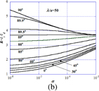
Fig. 3. (a) Current ratio R = is/id of spherical to disk electrodes vs α for λ/a = 50 and φ = 0, 30, 45, 60, 75, and 90°. (b) Current ratio R = is/id of spherical to disk electrodes vs α = 10−6 to 10−3 for λ/a = 50 and φ = 0, 30, 45, and 60° with greater detail between 80 and 90°.
Download figure:
Standard image High-resolution imageThe angle dependence becomes more marked as φ approaches 90°, so the case of φ = 90° may be useful for the detection of the direction of magnetic field. On the other hand, the angle dependence is weak near 0°. This suggests that the design is easy for a disk surface perpendicular to B because the disk current is insensitive to small tilt.
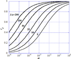
Figure 4 shows the dependence on λ/a of the plane probe current id for the case of φ = 0° (surface ⊥ B) vs α. As λ/a increases (the pressure becomes lower or the probe is smaller), the dependence of id on λ/a becomes weaker at α > 10−3.
Fig. 4. Dependence on λ/a of plane probe current id vs α for the case of φ = 0°. The plane probe surface is perpendicular to B.
Download figure:
Standard image High-resolution image
A double probe consisting of a planar disk and a sphere with the same radius can be useful for the investigation of the diffusion coefficient in the edge plasma, that is, the ratio R of the saturation currents of the two electrodes can give α if the parameters λ/a and φ are known.
The ratio of diffusion coefficients α ≡ D⊥/D∥ for classical diffusion is
while α for Bohm diffusion is
where D⊥ = κTe/16eB and D∥ = λvi/3 (λ: mean free path of ions) are used and ω and τ are the angular cyclotron frequency and the mean collision time of ions, respectively. Since α is a function of ωτ = ωλ/vi, the value of Ti can be estimated from α using Eq. (18) in the case of classical diffusion. The retarding part of the current–voltage characteristics of the disk for φ = 0 can give Te in the usual manner. Therefore, Ti can be estimated from α using Eq. (19) in the case of Bohm diffusion.
In summary, the applicable range of the present method is mainly in the edge plasma of helical and tokamak types whose parameters are no = 1017–1018 m−3, B of the order of Tesla and Te ≫ Ti. Therefore, we have the condition λD < ds ≪ a ≪ λ. It is almost collision free inside the sheath. The ion flow is anisotropic and governed by diffusion. The presheath is almost negligible but ns < no owing to the sink effect of the probe.
For example, in the edge of Heliotron J, we have B = 1.4–1.6 T, Te ∼ 20 eV, and no ∼ 7 × 10¹⁷ m−3. Using the collision cross section for hydrogen, σ ∼ 2 × 1016 cm2,15) we have τ = 2.9 × 10⁻⁶ s and ω = 6.1 × 10⁷ s−1. For the pressure of ∼10−3 Torr, we have λ = 20–50 cm. Then, λ/a = 40–100 in Figs. 2–4 are relevant values. The current ratio R = is/id shown in Figs. 3(a) and 3(b) serves to obtain D⊥/D∥. Using Eq. (18) or (19) depending on the diffusion modes, which must be determined by some other means, Ti is indirectly obtainable.
As an error source, the disk probe has no thickness. In order to reconcile this, a thin oblate spheroidal shape has been proposed, and the analytical form has been given. The accuracy of setting φ, especially near 90°, must be very high because R is very sensitive to φ. Other error sources such as probe supports and plasma noise, are common sources of error.
Acknowledgements
The present work is supported by the Joint Research Program on Zero-Emission Energy Research, Institute of Advanced Energy, Kyoto University.