
Abstract
LiF/CaF2/LiBaF3 ternary eutectic scintillators were grown by the µ-PD method. In the solidified eutectic the phases were uniformly distributed in the transverse direction and aligned along the growth direction. For the Eu-doped samples, the expected emission peak observed at 425 nm was ascribed to Eu2+ 5d–4f transition from Eu:CaF2 under X-ray excitation. The LiF/CaF2/LiBaF3 ternary eutectic scintillators showed a light yield around 7,000 photons/neutron and decay time of 260 ns (73.6%) and 50 ns (26.4%).
Export citation and abstract BibTeX RIS
1. Introduction
Inorganic scintillators have been playing a major role in many fields of radiation detection, including medical imaging, security systems, astrophysics, and well logging. In these applications, scintillators for thermal neutron detection have recently attracted much attention due to diminishing resources of 3He gas. Up to now, most of the thermal neutron detectors are the 3He gas counters with high thermal neutron cross section and low background gamma-ray sensitivity. However, the recent demand for 3He gas highly exceeds its supply because utilization of neutron detectors for homeland security and oil logging applications increased. Therefore, the alternative neutron detection systems have been searched for.1,2) This huge discrepancy between the demand and supply motivates us to develop novel thermal neutron scintillators which would replace the contemporary 3He based systems. In this decade, some novel inorganic scintillators for neutron detection have been reported. Among them, LiCaAlF6 based scintillator is the most promising candidate.3,4) LiCaAlF6 includes Li in the host lattice and has an ability of the pulse shape discrimination between neutrons and gamma-rays.5) As it is a single crystal, Li content is limited by the chemical formula. As a candidate for novel neutron detectors, Eu activated LiF/CaF2 eutectic scintillators were developed and their scintillation properties under 252Cf neutron exposure were examined.6,7) The most important advantage of eutectic scintillators is higher Li content when compared to conventional neutron scintillators like Li-glass, Eu:LiI, LiFIZnS.8) The interest in this study is not only to increase Li content but also the possible design of high resolution neutron imager using the directionally solidified eutectic (DSE) system coupled with high resolution photo detector. Possibility of high resolution using DSE system for X-ray CT application was demonstrated on GdAlO3 (GAP)–Al2O39) and CsI–NaCl.10) Several kinds of eutectics containing Li are investigated for neutron detection system, such as 6LiF/SrF2,11) 6LiF/CaF2,12) LiF/LiGdF4,13) LiF/LiYF4,14,15) LiF/LiLuF4,16) and LiF/LaF3.17) In addition to this, many studies and theories about ternary eutectic growth have been reported.18–21)
In this study, as a candidate for novel neutron detectors, Eu doped LiF/CaF2/LiBaF3 ternary eutectic scintillators were explored. The most important advantage of this eutectic scintillator is the Li content which is higher than that of the conventional neutron scintillators like Li-glass, Eu:LiI, or LiF:ZnS.8) In addition, this material is supposed to contain submicron-diameter phase-separated scintillator fibers (PSSFs) with both the properties of an optical fiber and a capability of neutron-to-light conversion. The PSSFs were fabricated as a DSE system. The DSE systems have been discovered for various material systems for many applications.8,9,22) In PSSFs, the light emitted from the scintillator fibers is confined and transported along the fiber direction by a total reflection mode as shown in Fig. 1, so that high-resolution neutron imaging can be achieved.
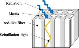
Fig. 1. Schematic of directionally solidified scintillator.
Download figure:
Standard image High-resolution image2. Experimental procedure
The starting material was prepared from LiF, CaF2, BaF2, and EuF3 powders (4N). LiF/CaF2/LiBaF3 ternary eutectics were grown at the composition corresponding to the eutectic point. Crystal growth was performed by the micro-pulling-down (µ-PD) method with the vacuum-tight chamber. The starting composition were non-doped: 67.89%LiF/16.30%CaF2/15.81%BaF2 and Eu-doped: 67.89%LiF/16.14%CaF2/15.81%BaF2/0.16%EuF3. Mixed powder was set in a graphite crucible with a 3 mm die which has a 2 mm hole in the center. The crucible was heated by the high-frequency induction coil in Ar/CF4 gas mixture after baking process under high vacuum (∼10−4 Pa). The melt in the crucible was pulled down using platinum wire seed at 1.0 mm/min. The detail of crystal growth by the µ-PD method was described in Refs. 23 and 24. Circular samples were obtained from the grown crystal. The cut surface was optically polished and carbon-coated. The eutectic structure was observed by back scattered electron image (BEI) using Hitachi S3400N scanning electron microscope. The phases in the eutectics were determined from the powder X-ray diffraction (XRD) patterns. Emission spectra of the circular Eu-doped sample which was cut and polished with 1 mm-thickness were measured with the setup depicted in Ref. 25. The sample was excited by monochromatic UV photons using a xenon lamp (150 W) and a monochromator (Princeton Instruments SP2150i) controlled by a computer. In this experimental setup, the sample was placed within the integrating sphere, opposite to the fiber with UV excitation light. Emission light was collected by another optical fiber. The emitted photons were detected using two spectrophotometers (Hamamatsu PMA-12).
Sample pieces with dimensions of 3ϕ × 1 mm3 were cut and polished from the grown crystal. To determine the light yield, the energy spectra were collected under neutron excitation from 252Cf radiation source by using a (PMT; Hamamatsu H7600U-200, super bialkali photocathode, quartz window). The 3ϕ mm2 face of the pieces was coupled with the PMT by using optical grease (OKEN 6262A). The pieces were covered by using Teflon-tape. The signal was fed into a shaping amplifier (ORTEC 572A), a multichannel analyzer (MCA; ORTEC 926), and finally to a personal computer. The shaping time was set as 2 µs. The bias for the PMT was supplied by an ORTEC 556. Pulse-height spectra and decay time under neutron excitation from a 252Cf radiation source were investigated using a PMT (Hamamatsu R7600U-200). The polished samples were optically coupled to the window of the PMT with an optical grease (OKEN 6262A). In the measurements, 6Li-loaded glass scintillator (Saint Gobain GS20) with a size of 1 × 2 × 6 mm3 which had the light yield of 6,000 photons/neutron26) was used as a reference. Scintillation decay curves were observed by using the PMT and a digital oscilloscope TD5032B irradiated by the 252Cf radiation source.
3. Results
3.1. Growth and phase investigations of the LiF/CaF2/LiBaF3 eutectics
The LiF/CaF2/LiBaF3 eutectics were prepared by the µ-PD method as shown in Figs. 2(a)–2(d) show Eu-doped eutectics grown at the speed of 0.16 mm/min, non-doped crystal grown at the speed of 0.04 mm/min, non-doped crystal grown at the speed of 0.16 mm/min, and non-doped crystal grown at the speed of 0.64 mm/min, respectively. The BEIs of transverse cross-section of the eutectic are shown in Fig. 3. The three phases seem to be uniformly dispersed. The size of each phase become smaller as the growth speed becomes higher. In addition to the change, the shape was change from triangle-like to circular-like as the speed becomes higher. The BEIs of vertical cross-section along the growth direction are shown in Fig. 4. Mainly black phase and white phase were well aligned along the growth direction. In Figs. 4(c) and 4(d), well aligned structure was observed. The edge of the eutectic crystal grown at the speed of 0.16 mm/min was shown in Fig. 4(e) and each phase was well aligned. Increasing the growth speed, the phases were better aligned and the irregular phase structures were eliminated. The obtained phases were determined using EDX and XRD patterns shown in Figs. 5 and 6, respectively. These phases were determined as follows, White:LiBaF3, Gray:CaF2, and Black:LiF. The directional solidification of ternary eutectics along the growth direction was confirmed by the above results. In binary eutectic growth, some groups investigated transformation between rod-like shape and lamellar shape in eutectic structure.27–30) They conclude that eutectic's transformation depended on the volume ratio of components and the relative interface energy.31) In the case of the ternary eutectic growth in this study, the size of the each phases became smaller as the growth speed increased. This is a good agreement with reported eutectic growth in binary13–15) and ternary18,19,21) eutectics studies and models. In ternary eutectics studies, the interfacial energy of each phase and the match of plane are important for well aligned directional solidified structure.19–21)

Fig. 2. Photographs of grown LiF/CaF2/LiBaF3 eutectics, (a) Eu-doped crystal grown at the speed of 0.16 mm/min, (b) non-doped crystal grown at the speed of 0.04 mm/min, (c) non-doped crystal grown at the speed of 0.16 mm/min, and (d) non-doped crystal grown at the speed of 0.64 mm/min.
Download figure:
Standard image High-resolution image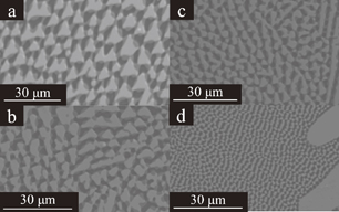
Fig. 3. BEI of polished LiF/CaF2/LiBaF3 eutectics, (a) transverse cross-section of the Eu-doped crystal grown at the speed of 0.16 mm/min, (b) transverse cross-section of the non-doped crystal grown at the speed of 0.04 mm/min, (c) transverse cross-section of the non-doped crystal grown at the speed of 0.16 mm/min and (d) transverse cross-section of the non-doped crystal grown at the speed of 0.64 mm/min.
Download figure:
Standard image High-resolution image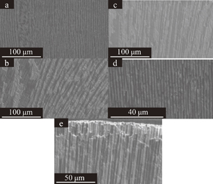
Fig. 4. BEI of polished LiF/CaF2/LiBaF3 eutectics, (a) vertical cross-section of the Eu-doped crystal along the growth direction at the speed of 0.16 mm/min, (b) vertical cross-section of the non-doped crystal along the growth direction at the speed of 0.04 mm/min, (c) vertical cross-section of the non-doped crystal along the growth direction at the speed of 0.16 mm/min, (d) vertical cross-section of the non-doped crystal along the growth direction at the speed of 0.64 mm/min, and (e) the fiber-like structure of the non-doped crystal grown at the speed of 0.16 mm/min.
Download figure:
Standard image High-resolution image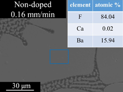
Fig. 5. BEI of polished LiF/CaF2/LiBaF3 eutectics on transverse cross-section and EDX analysis of element concentration about the area of white primary phase enclosed by blue line.
Download figure:
Standard image High-resolution image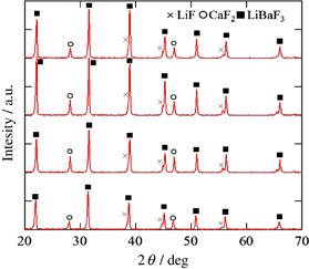
Fig. 6. Powder XRD pattern for the LiF/CaF2/LiBaF3 eutectic.
Download figure:
Standard image High-resolution image3.2. Luminescence and radiation responses
Photoluminescence spectra measured under excitation at 290 nm by monochromatic UV photons using a xenon lamp (150 W) and a monochromator (Princeton Instruments SP2150i) controlled by a computer is shown in Fig. 7. Two peaks can be observed in the spectra at 360 and 425 nm. The broad 425 nm emission is ascribed to 5d–4f transition of Eu2+ according to the previous reports on Eu2+:CaF232) and Eu2+:LiBaF3.33) The sharp 360 nm peak was ascribed to the 6P7/2 → 8S7/2 transitions in the 4f7 electronic configuration of Eu2+.33) Figure 8 shows the pulse height spectra of the eutectic under 252Cf neutron excitation. As can be clearly seen, neutron peaks were detected in both of the samples. The quantum efficiencies of the PMT at 380 nm (emission of Li-glass) and 425 nm (Eu:CaF2) are approximately 40% and we can directly compare their light yields from the 252Cf neutron peak channels. The light yield of Eu-doped LiF/CaF2/LiBaF3 eutectic was around 7000 ph/n. This value is the same as that of Eu:CaF2/LiF eutectic in our previous report (7000 ph/n).34) Figure 9 shows the scintillation decay curve of the eutectic under 252Cf neutron. The scintillation decay curve is approximated by the sum of two exponentials according to the following equation:

Ratio (%) is calculated by A1τ1/(A1τ1 + A2τ2) × 100%. The decay curve were fitted to two decay components with decay times of about 260 ns (73.6%) and 50 ns (26.4%). Slower decay was well comparable to the decay time of Eu2+ in CaF2 5d–4f transition.34)
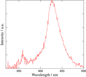
Fig. 7. Emission spectrum under Xe-lump excited at 290 nm.
Download figure:
Standard image High-resolution image
Fig. 8. Pulse-height spectra of Eu-doped LiF/CaF2/LiBaF3 eutectic under 252Cf neutron excitation. Red line is Eu-doped eutectic and blue line is Li-glass.
Download figure:
Standard image High-resolution image
Fig. 9. Decay curve of Eu-doped LiF/CaF2/LiBaF3 eutectic under 252Cf neutron excitation.
Download figure:
Standard image High-resolution image
4. Conclusion
The LiF/CaF2/LiBaF3 eutectic scintillator have been grown by µ-PD method. Li concentration in the LiF/CaF2/LiBaF3 eutectic is around 67.9 mol %. This is the advantage for neutron detection because 6Li has high neutron capture cross-section.
In the investigation of scintillation properties, fast decay time of about 260 ns (73.6%) and 50 ns (26.4%), and high light yield of 7000 photons/neutron were obtained.
Our PSSFs system is promising for neutron imaging application such as detector for neutron diffraction, nondestructive inspection, etc. In the eutectic, each phase was uniformly dispersed in transverse direction and slightly aligned along the growth direction.
Better aligned and transparent LiF/CaF2/LiBaF3 eutectics can be grown after optimization of growth conditions by the same investigation as shown in the previous report9) and scintillation properties such as light yield can be improved.
Acknowledgements
This work is partially supported by (i) the Funding Program for Next Generation World-Leading Researchers of JSPS, (ii) Development of Systems and Technology for Advanced Measurement and Analysis, Japan Science and Technology Agency (JST), (iii) Adaptable & Seamless Technology Transfer Program through Target-driven R&D (A-STEP), JST, (iv) Japan Society for the Promotion of Science (JSPS) Grant-in-Aid for Exploratory Research (A.Y.), (v) JSPS Research Fellowships for Young Scientists (S. Kurosawa) and (vi) the Health Labour Sciences Research Grant, the Ministry of Health Labour and Welfare. In addition, we would like to thank the following persons for their support: Mr. Yoshihiro Nakamura in Institute of Multidisciplinary Research for Advanced Materials (IMRAM), Tohoku University and Mr. Hiroshi Uemura, Ms. Keiko Toguchi, Ms. Megumi Sasaki, Ms. Yuka Takeda, and Ms. Kuniko Kawaguchi in IMR.