
Abstract
The electrochemical properties of lithium–oxygen batteries are improved by coating a tungsten carbide layer onto an oxygen cathode. Tungsten carbide (WC) coating is conducted by physical vapor deposition. The uniform deposition of WC onto the cathode is confirmed by scanning electron microscopy, field-emission transmission electron microscopy and electron probe microanalysis. The discharge-recharge voltage gap of the cell with a WC-coated electrode is estimated to be 0.88 V, which is 700 mV smaller than that of an electrode without the WC coating at 100 mA g−1carbon. The overpotentials of the WC-coated electrode remain unchanged even after the 10th cycles, while that of the uncoated electrode gradually increases. In addition, the WC-coated electrode exhibits a stable voltage profile, even at a current density of 200 mA g−1carbon. The observed improvement in cell performance can be attributed to the catalytic property and high electrical conductivity of WC. The enhanced electrochemical properties of cells are examined by impedance analysis and SEM.
Export citation and abstract BibTeX RIS
1. Introduction
Lithium-ion batteries have become an integral part of our daily life, with their widespread use in various electronic devices. Further, recently, many studies have been carried out on electric vehicles (EVs).1,2) However, owing to the energy-density limit of the lithium-ion batteries, many studies have focused on developing batteries with different structures. Furthermore, many studies about lithium metal batteries with unique operating mechanisms are in progress.3) Among such batteries, lithium-air batteries have attracted worldwide attention.3,4) Non-aqueous lithium oxygen batteries are one of the most promising energy storage systems for electric vehicles and various electric devices because the expected gravimetric energy density is 5–10-fold higher than that of lithium-ion batteries.4) Lithium-air batteries have no intercalation reaction unlike normal lithium-ion batteries. Instead, Li ions chemically react with oxygen in the atmosphere on a porous electrode and lithium peroxide is formed as the reaction product [2Li+ + 2e− + O2 ↔ Li2O2(s)] on discharging (∼3,500 W h kg−1 including the mass of oxygen).5–7) However, in the case of lithium-air batteries using a non-aqueous electrolyte, the oxygen reduction reaction (ORR) (during discharge) and oxygen evolution reaction (OER) (during charge) are rather slow.8–10) In addition, the lithium peroxide formed during the discharge is an insulator and is insoluble in the non-aqueous electrolyte.11,12) Thus, over time, the product tends to accumulate on the cathode (porous electrode), thereby hindering the effective oxygen pathway of the porous electrode. This accumulation of lithium peroxide and the consequent blocking of oxygen pathways result in gradual reductions in oxygen supply, overpotentials and poor round-trip efficiency.13,14) Many studies have been conducted to find catalysts which lower the over-potential and improve the cycling performance. Bruce et al. studied Li–air batteries using MnO2 nanowires as catalysts, which resulted in an initial discharge capacity of 3000 mA h g−1 at a current of 70 mA g−1.15) Also, Yang et al. worked on Li–air batteries using PtAu nanoparticles as bifunctional catalysts (2200 mA h g−1 at 50 mA g−1). The discharge voltage of the Li–air batteries using PtAu bifunctional catalysts is higher than that of carbon by 150 mV and the charge voltage of PtAu/C is 3.8 V, which is lower than that of pure carbon by 700 mV.16) That is, the catalyst plays a key role in improving the power density, stable cyclability and energy efficiency.16,17)
In this study, the abovementioned problem can be circumvented by coating a uniform tungsten carbide (WC) layer onto a cathode by physical vapor deposition (PVD). The WC has been demonstrated to be efficient catalysts in replacing noble metals for the ORR in fuel cells.18,20) Thus, WC is used for the first time as a catalyst in non-aqueous Li–O2 batteries. In order to exhibit an effective catalytic activity of WC, the WC layer is coated onto the cathode by uniformly dispersing WC. The WC with high electrical conductivity (∼2 × 10⁷ S m−1) and excellent catalytic activity comparable to that of platinum18–22) helps in improving the capacity, decreasing the discharge-recharge voltage gap and improving the rate capability.
2. Experimental methods
2.1. Preparation of WC-coated O2 cathode
A cathode material was prepared by mixing Ketjen black (KB) carbon (Ketjen Black EC600-JD, specific surface area: 1270 m2 g−1) and the binder (PVDF) dissolved in N-methyl-2-pyrrolidone, in the weight ratio of  . Following that, the O2 cathode was prepared by uniformly casting the slurry onto Ni foam. In order to retain the porosity of the fabricated cathode, the slurry coated nickel foam was slightly blown with an air gun. The O2 cathode thus obtained was dried at 80 °C for 24 h. Subsequently, the O2 cathode was coated with WC by PVD (Dongwoo Surface Tech) (Fig. 1). In order to generate plasma, C2H2 gas was injected in a chamber. Thus, after the plasma tore off the tungsten carbide material (target), it was deposited on a substrate (electrode). The deposition was carried out for the duration of 5 min at a temperature of 100 °C. The thickness of the resulting WC coating was approximately 20 nm. The morphology of the O2 cathode before and after cycling was observed by using scanning electron microscopy (SEM; Hitachi S-4300). Furthermore, the WC-coated O2 cathode was analyzed by field-emission transmission electron microscopy (FETEM), energy-dispersive X-ray spectroscopy (EDX) and electron probe microanalysis (EPMA). The sample for TEM analysis was prepared using a focused ion beam (FIB).
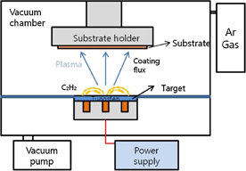
Fig. 1. Schematic diagram of PVD equipment for WC coating.
Download figure:
Standard image High-resolution image2.2. Cell assembly and electrochemical measurements
The electrochemical properties of the WC-coated O2 cathode were analyzed by assembling a cell using a HS flat cell (Fig. 2). In the typical process, the electrochemical cell was assembled with Li metal as the anode, a glass microfiber filter paper (Whatman GF/C) soaked in the electrolyte consisting of 1 M lithium bis(trifluoromethylsulfonyl)imide (LiTFSI) in tetraethylene glycol dimethyl ether (TEGDME), and the WC-coated O2 cathode prepared by casting the active material onto Ni foam, with the HS flat cell in a dry room. The cell was assembled completely gastight, except that the WC-coated O2 cathode was exposed to oxygen atmosphere through a pipe. Cell testing was performed under 1 atm of O2. The performance of the cell with a WC-coated electrode was compared with that of the cell with an uncoated KB electrode assembled under the same experimental condition. The electrochemical performance of the cell was analyzed by a galvanostatic discharge/charge method (WonATech WBCS 3000) at constant current densities of 100 and 200 mA g−1carbon for a limited duration of 10 h. The impedance measurements (Solatron SI1280B) were performed in the frequency range of 10−2 to 105 Hz at an AC amplitude of 5 mV. The corresponding impedance data was displayed by using Z-view software (Scribner Associates).

Fig. 2. Design and configuration of the Li–O2 cell.
Download figure:
Standard image High-resolution image3. Results and discussion
3.1. Characterization of WC-coated electrode
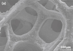
Figure 3 shows the SEM images of the bare KB electrode (uncoated O2 cathode) [Fig. 3(a)] and WC-coated O2 cathode [Fig. 3(b)]. As is seen, no significant changes in the morphology can be observed between the KB electrode and WC-coated electrodes. Therefore, further studies on the uniformity of the WC coating are performed by EPMA (Fig. 4). The EPMA mapping of the WC-coated O2 cathode indicates uniform distributions of elemental tungsten and carbon, suggesting the uniform coating of WC onto the O2 cathode. This is further confirmed by TEM analysis, which reveals that the WC-coating layer thickness is approximately 20 nm (Fig. 5). The image represents that the WC-coating layer is uniformly deposited on the electrode. This indicates that the WC has good adhesion onto the active materials in the cathode.23) The presence of tungsten and carbon on the surface of the electrode is further confirmed by EDX analysis (Fig. 5). Furthermore, the carbon in the active material is distinguished from the carbon in WC via point profiling by EDX analysis. Results indicate the existence of carbon in the coating layer, confirming the uniform coating of WC onto the O2 cathode.
Download figure:
Standard image High-resolution image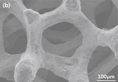
Fig. 3. SEM images of the (a) uncoated electrode and (b) WC-coated electrodes.
Download figure:
Standard image High-resolution image
Fig. 4. Mapping image of the WC-coated electrode by EPMA.
Download figure:
Standard image High-resolution image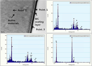
Fig. 5. TEM image and EDX analysis of WC-coated electrode.
Download figure:
Standard image High-resolution image3.2. Electrochemical performance of the WC-coated cell
We determine the effects of the catalytic property and high electrical conductivity of the WC on the capacity of the cell. The Li–O2 batteries are discharged at a current density of 100 mA g−1carbon, as shown in Fig. 6. Discharged to the limiting voltage of 2.0 V, the cell with the WC-coated electrode presents a higher capacity of 7000 mA h g−1carbon when compared to the cell with the KB electrode (3200 mA h g−1carbon). Indeed, a capacity of more than double of the KB cell is obtained. The observed increase in the initial capacity of the cell with the WC-coated electrode can be attributed to its catalytic property and high electrical conductivity.18–22)
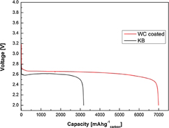
Fig. 6. Initial discharge capacities of the uncoated KB and WC-coated cells at the current density of 100 mA g−1.
Download figure:
Standard image High-resolution imageThat is, it is observed that Li2O2 is efficiently generated with the help of the WC catalytic effect on the ORR during discharge, and the evenly coated WC mitigates the accumulation of Li2O2 that uniformly induces the generation of Li2O2 on the electrode. Consequently, the quantity of Li2O2 increases, leading to capacity enhancement.
Figure 7 shows the cycling behavior of batteries with bare KB and WC-coated cells for the first cycle and 10th cycles at a current densities of 100 and 200 mA g−1carbon. The voltage profile of the KB cell is compared with that of the WC-coated cell at 100 mA g−1carbon. The first discharge and charge voltages of the KB cell are observed to be 2.65 and 4.23 V, respectively, while the first discharge and charge voltages of the WC-coated cell are observed to be 2.75 and 3.63 V, respectively [Fig. 7(a)]. The 10th discharge–charge voltages of the uncoated cell (KB) are observed to be 2.3 and 4.4 V, respectively, while the corresponding values of the WC-coated cell are observed to be 2.74 and 3.64 V, respectively. [Fig. 7(b)]. The first discharge–charge voltage gap ("overpotentials") of the cell with the WC-coated electrode is estimated to be 0.88 V which is 700 mV smaller than that of the cell with the KB electrode at a current density of 100 mA g−1carbon. Also, the 10th discharge–charge overpotentials of the cell with the WC-coated electrode is estimated to be 0.9 V, which is 1200 mV smaller than that of the cell with the KB electrode at a current density of 100 mA g−1carbon. The KB cell shows a gradual increase in discharge–charge overpotentials during the 10th cycles, while the WC-coated cell does not exhibit any voltage change during the 10th cycles. Moreover, the KB cell leads to the complete failure of the cell after approximately the 14th cycles. The decreases in overpotentials during the charge and discharge can be explained on the basis of the catalytic effect of WC, which is similar to that of the platinum.18,20,24) In other words, the overpotentials respectively decreases and increases during the charge and discharge cycling processes owing to the catalytic effect of WC that favors the rapid creation and decomposition of the reaction product (Li2O2).
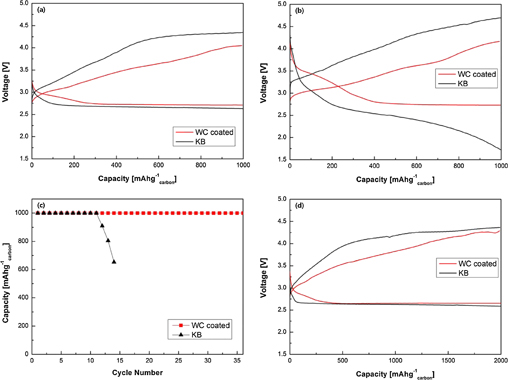
Fig. 7. Voltage profiles of the KB and WC coated cells (a) after first cycle and (b) 10th cycles. (c) KB and WC-coated cells with a limited capacity of 1000 mA g−1carbon at the current density of 100 mA g−1carbon. (d) Voltage profiles of the KB and WC-coated cells after first cycle at the current density of 200 mA h g−1.
Download figure:
Standard image High-resolution imageIt should be noted that the overpotentials of both the ORR and OER gradually increased, probably owing to the accumulation of incompletely decomposed Li2O2 and side reaction products, which might have resulted from the decomposition of the TEGDME solvent even below 4.2VLi28–30) and the TEGDME–O2 reaction. The accumulation of reaction products causes the slow performance and capacity degradation along with an increase in the number of cycles. A very improved cyclability can be achieved by using the WC to limit the discharge–charge overpotentials.
Figure 7(c) shows that the WC-coated cell can considerably enhance the cycle life with a current density of 1000 mA g−1carbon. After the 12th cycles, the cell with the KB electrode exhibits capacity decrease, unsuitable for further use. On the other hand, the cell with the WC-coated electrode efficiently operates beyond the 36th cycles, albeit with a slight increase in overpotentials. The observed increases in cycle stability and round-trip efficiency can be attributed to the improvement in reaction rate and decrease in discharge or charge voltage gap,25) as a result of the high electrical conductivity and catalytic activity of WC.
We further substantiate this observation by performing cell tests at a high current density. The voltage profiles of the KB and WC-coated cells are compared at a high current density of 200 mA g−1carbon. As is seen, the first discharge and charge voltages of the KB cell are 2.61 and 4.25 V, respectively [Fig. 7(d)]. However, the WC-coated cell shows a decreased overpotentials, as indicated by the first discharge and charge voltages of 2.66 and 3.94 V, respectively [Fig. 7(d)]. This can be attributed to the catalytic properties and the high electrical conductivity of WC, which results in a higher rate capability performance.27) These results once again confirm the benefits of the coating of WC onto the O2 cathode.
To obtain further insights into the discharge and charge processes of Li–O2 batteries with the uncoated (KB) and WC-coated cells, a SEM technique is employed to analyze the surface morphology at discharge–charge stages, as presented in Fig. 8. Figures 8(a) and 8(b) show the initial morphologies of the KB and WC-coated electrodes, demonstrating that both electrodes are composed of carbon and microspheres. The WC coating layer is too thin to be distinguished. After discharge, the carbon and microspheres are covered by massive Li2O2, as shown in Figs. 8(c) and 8(d). Based on previous report,31) it can be considered that Li2O2 (discharge product) gradually blocks microspheres. The morphologies of the KB and WC-coated electrodes after subsequent charge are shown in Figs. 8(e) and 8(f). For the KB electrode, Li2O2 is not completely decomposed. After charge, the remaining Li2O2 is observed as a Li2O2 film, blocking microspheres.11,32) Li2O2 with low electronic conductivity33) covers the surfaces of microspheres and would further block the pathways for oxygen diffusion and electron transfer. Thus, these results lead to the low cycling performance of Li–O2 batteries.34) As for the WC-coated electrode, Li2O2 disappears after charge. This demonstrates that the WC coating layer can facilitate the effective decomposition of discharge products.
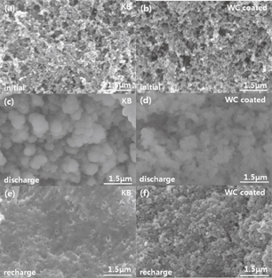
Fig. 8. SEM images of the (a) initial KB and (b) initial WC-coated cathodes. After discharge, images of the (c) KB cathode and (d) WC-coated cathodes. After recharge, images of the (e) KB cathode and (f) WC-coated cathodes.
Download figure:
Standard image High-resolution imageElectrochemical impedance spectroscopy measurements of the uncoated (KB) and WC-coated cells are performed before and after the 10th charge cycles (Fig. 9). As is seen, the WC-coated cell obviously improves its impedance results. Before the charge cycling, the radius of the semicircle in the Nyquist plot of the cell with the WC-coated electrode is smaller than that of the cell with the uncoated electrode (KB). This demonstrates that the high electrical conductivity of the WC coating reduces charge transfer resistance.26) Likewise, after the 10th cycles, the radius of the semicircle in the Nyquist plot of the cell with the WC-coated electrode is smaller than that of the cell with the uncoated electrode. The catalytic effect of WC also affects charge transfer resistance during discharge–charge. As the cycling proceeds for the KB electrode, the product decomposition is not completely finished [Fig. 8(e)] on charge, that is, Li2O2 of low electronic conductivity accumulates with charge transfer resistance increase. However, in the case of the WC-coated cell, the charge transfer resistance increment is reduced by the excellent catalytic effect on the OER, on which the reaction product is effectively decomposed. This could be attributed to the excellent catalytic effect of WC, which decreases the charge transfer resistance at the interface.

Fig. 9. AC impedance analysis data of KB cell and WC-coated cells before cycling and after the 10th recharge.
Download figure:
Standard image High-resolution image
These results suggest that the WC coating improves the electrochemical properties of the electrode. When compared to Li–air batteries using MnO2 nanowires as catalysts (3000 mA h g−1 at 70 mA g−1)15) and Li–air batteries using PtAu nanoparticles as bifunctional catalysts (2200 mA h g−1 at 50 mA g−1),16) we also observed good catalytic activity of WC from the rate capacity (7000 mA h g−1carbon at 100 mA g−1) and the decrease in overpotentials. That is, WC as a catalyst is suitable as an effective coating material. However, the performance of the WC coated cell gradually terminates after the 37th cycles at 100 mA g−1carbon since the WC coating could only act as a catalytic source but could not effectively suppress the side reactions (Li2CO3, HCO2Li) during discharge. Also, the oxidation of the lithium metal anode is not suppressed on discharge–charge. To compensate for the defects, we propose research studies on a dual-coated electrode with WC and other stable materials that can suppress the formation of byproducts or the fabrication of an electrochemically stable electrolyte that can minimize the side reactions. Finally, in order to stop the oxidation of lithium and enhance ionic conductivity, we suggest ionic conductivity polymer coating on the lithium metal anode.
4. Conclusions
The effect of WC coating on the electrochemical performance of an O2 electrode has been analyzed. In this study, WC was uniformly coated onto the nickel foam containing an active material by physical vapor deposition. Results indicate an enhancement in the electrochemical performance of an air cell with a WC-coated electrode. In particular, we observed a significant increase in rate capacity (7000 mA h g−1carbon) when compared with that in the case of the cell with a KB electrode. The first charge and discharge voltage of the KB electrode were 4.23 and 2.65 V at 100 mA g−1carbon, while the first charge and discharge voltages of the WC-coated cell were 3.63 and 2.75 V, respectively. With repeated cycling, the overpotentials of the KB cell increased substantially, while that of the WC-coated electrode remained almost unchanged, resulting in a stable voltage profile over long cycles. In addition, the cell with the WC-coated electrode exhibited good electrochemical performance even at a high current density of 200 mA g−1carbon. The observed decrease in discharge and charge overpotentials, the improvement in cycle life, and the enhancement in rate capability could be attributed to the catalytic effect facilitating ORR/OER and high electrical conductivity of WC. These results indicate that WC as a catalyst is an excellent coating material for improving the electrochemical performance characteristics of lithium–oxygen batteries.
Acknowledgments
This study was supported by a National Research Foundation of Korea (NRF) grant funded by the Korean government (MEST) (2011-0028757). The microstructure of the samples was observed by TEM; the equipment was located at the Korea Basic Science Institute Seoul Center. WC was coated onto the O2 electrode by PVD, at the Dongwoo Surface Tech Co., Ltd.