


 nchen, Germany

ABSTRACT
We carried out deep- and wide-field near- and mid-infrared observations for a sample of eight bright-rimmed clouds (BRCs). Supplemented with the Spitzer archival data, we have identified and classified 44 to 433 young stellar objects (YSOs) associated with these BRCs. The Class I sources are generally located toward the places with higher extinction and are relatively closer to each other than the Class II sources, confirming that the young protostars are usually found in regions with denser molecular material. On the other hand the comparatively older population, Class II objects, are more randomly found throughout the regions, which can be due to their dynamical evolution. Using the minimal sampling tree analyses, we have extracted 13 stellar cores of eight or more members, which contain 60% of the total YSOs. The typical core is ∼0.6 pc in radii and somewhat elongated (aspect ratio of 1.45), of relatively low stellar density (surface density 60 pc−2), consisting of a small (35) number of YSOs of relatively young sources (66% Class I), and partially embedded (median AK = 1.1 mag). But the cores show a wide range in their mass distribution (∼20 to 2400 M⊙), with a median value of around 130 M⊙. We found the star-formation efficiencies in the cores to be between 3% and 30% with an average of ∼14%, which agrees with the efficiencies needed to link the core mass function to the initial mass function. We also found a linear relation between the density of the clouds and the number of YSOs. The peaked nearest neighbor spacing distributions of the YSOs and the ratio of Jeans lengths to the YSO separations indicates a significant degree of non-thermally driven fragmentation in these BRCs.
Export citation and abstract BibTeX RIS
1. INTRODUCTION
Observations of embedded star-forming regions (SFRs) show that stellar distributions in SFRs are often elongated, clumpy, or both (see Lada & Lada 2003; Gutermuth et al. 2005, 2008; Teixeira et al. 2006; Allen et al. 2007; Koenig et al. 2008), and seems to be correlated with the distribution of dense gas of the natal molecular clouds (Gutermuth et al. 2008). Mapping the spatial distribution of young stellar objects (YSOs) within these SFRs is an important means by which one can study the star-formation scenario in the region and understand the physical processes that influence star formation (Koenig et al. 2008).
Surveys of molecular clouds in the nearest 1 kpc show that approximately 75% of embedded young stars are in groups and clusters with 10 or more members (Zinnecker et al. 1993; Carpenter et al. 2000; Allen et al. 2007). Gutermuth et al. (2009) have isolated several young stellar cores associated with each of a sample of 36 young stellar clusters and have studied their structures. The quantitative statistical properties of these structures—especially the sizes, densities, and morphologies of young stellar cores—could be used to test the theoretical models of star formation (Schmeja et al. 2009; Kuhn et al. 2014). While stars in some SFRs are centrally concentrated with a smooth radial density gradient, in other SFRs stars show signs of fractal sub-clustering. How the different structures are connected to the environmental conditions of the molecular clouds and how they depend on the evolutionary stage of the cluster are not yet clear.
Bright-rimmed clouds (BRCs), which are small, more or less isolated molecular clouds found at the edges of large H ii regions, usually show the presence of a group of young stars near the heads of a pillar of gas that point toward the central O/B stars in the region. These clouds may have resulted through the compression of pre-existing molecular clumps in the molecular cloud via a photoionization-induced shock and are potential sites of triggered SFRs (known as radiatively driven implosion, RDI; Bertoldi 1989; Lefloch & Lazareff 1994). Numerical simulations on the dynamical evolution of a molecular clump illuminated by the ionizing radiation of OB stars can be very useful for understanding the RDI process (e.g., Miao et al. 2006).
Relative isolation and simple geometry of BRCs make them an ideal laboratory to observationally test the RDI star formation. Sugitani and collaborators (Sugitani et al. 1991; Sugitani & Ogura 1994) compiled a catalog of 89 BRCs (commonly referred to as the SFO catalog) spread throughout the Galaxy: 44 clouds located in the northern hemisphere and 45 clouds located in the southern hemisphere. These clouds were identified by correlating IRAS point sources—having colors consistent with embedded protostars—with clouds displaying optically bright rims from the Sharpless H ii region catalog (Sharpless 1959) and the ESO(R) Southern Hemisphere Atlas. Using the submillimeter continuum observations, Morgan et al. (2008) demonstrated the presence of at least one core in 39 of the 45 BRCs they studied. The morphology of these BRCs is, in general, supportive of the scenario seen in RDI models: a dense core at the head of an elongated column along with the presence of young stars. Urquhart et al. (2009) used CO, mid-infrared (MIR), and radio data to identify 24 of the 45 southern BRCs that are undergoing a strong interaction with their H ii region and classified them as triggered candidates. Fourteen of these 24 interacting BRCs were found to show active star formation on the basis of being associated with embedded MIR point sources. The remaining BRCs either did not show any sign of triggered star formation or they were at an earlier evolutionary stage of star formation. While some individual clouds from the SFO catalog have been studied in detail (e.g., Lefloch et al. 1997; Megeath & Wilson 1997; Codella et al. 2001; Thompson & White 2004; Urquhart et al. 2004, 2006, 2007, 2009; Morgan et al. 2008) and have been shown to harbor protostellar cores, the question of whether star formation is a common occurrence within BRCs is still unresolved (Morgan et al. 2008). It is essential to carry out a census of YSOs in these SFO BRCs to determine the present status of star formation within them and relate it to their physical properties and morphologies. In particular, a systematic statistical study of the structure of the resultant stellar systems of BRC star-forming activities adjacent to H ii regions under the influence of high mass O/B stars has not been made to date.
The main aim of the present study is to investigate statistically the star-forming activities in BRCs, especially the structure of the resultant stellar systems or aggregates and its possible origin. Therefore, for our study, we selected eight triggered BRCs (cf. Table 1) from the SFO catalog that are currently showing active star formation. These BRCs are located at heliocentric distances ranging from 0.95 to 2.80 kpc and are distributed in the Galactic longitude (l) between 250° and 340° and latitude  . The distances of these BRCs have been taken from the available literature (Yamaguchi et al. 1999; Urquhart et al. 2009, and references therein) and were derived mostly from the photometric data of the O-type stars that are being assigned as the exciting star(s) of the H ii regions in which these BRCs are located. For bright stars at the distance of 1–3 kpc, one can expect small photometric errors (<1%–2%), and after taking care of the errors associated with intrinsic main sequence (MS), reddening values, and fitting, we can safely assume that the error in the distances can be ∼5%–15% (Phelps & Janes 1994).
Table 1. Regions Observed in the Present Study
| Name | α2000 | δ2000 | l | b | Distance | Pixel | 90% Completeness |
|---|---|---|---|---|---|---|---|
| (h:m:s) | (o:':'') | (degrees) | (kpc) | Size (pc) | Limit (M⊙) | ||
| SFO 54 | 08:35:31.7 | −40:38:28 | 259.941383 | −0.040549 | 0.95 | 0.0014 | 0.04(0.15) |
| SFO 55 | 08:41:13.0 | −40:52:03 | 260.775002 | 0.678340 | 1.15 | 0.0017 | 0.03(0.10) |
| SFO 64 | 11:12:18.0 | −58:46:20 | 290.374065 | 1.661209 | 2.70 | 0.0040 | 0.40(1.40) |
| SFO 65 | 11:33:00.0 | −63:27:20 | 294.301328 | −1.905817 | 1.70 | 0.0025 | 0.08(0.20) |
| SFO 68 | 11:35:31.9 | −63:14:51 | 294.511530 | −1.623458 | 1.70 | 0.0025 | 0.08(0.20) |
| SFO 75 | 15:55:50.4 | −54:38:58 | 327.573745 | −0.851722 | 2.80 | 0.0041 | 0.80(3.00) |
| SFO 76 | 16:10:38.6 | −49:05:52 | 332.956319 | 1.803776 | 1.80 | 0.0027 | 0.15(1.40) |
| SFO 79 | 16:40:00.1 | −48:51:45 | 336.491077 | −1.475060 | 1.35 | 0.0020 | 0.10(2.00) |
| Field 1 | 08:34:42.4 | −40:40:45 | 259.878445 | −0.188092 | ⋯ | ⋯ | ⋯ |
| Field 2 | 16:39:03.7 | −48:51:34 | 336.390516 | −1.357565 | ⋯ | ⋯ | ⋯ |
Note. The last column gives the stellar mass at the completeness limit of YSO detection after correcting for foreground and peak (in parenthesis) extinction values (cf. Section 3.2).
Download table as: ASCIITypeset image
In the optical, the challenge of studying BRCs is their association with high column density molecular clouds. Wide-field near-infrared (NIR) cameras installed on moderate size telescopes are needed to probe BRCs with sensitivity to detect subsolar mass objects as well as the angular resolution to resolve high-density groupings or aggregates of stars. The wider field of view (FOV) is also necessary to observe the distribution of stars over multiparsec distances (cf. Gutermuth et al. 2005). In the present study, we carry out deep-NIR observations with an Infrared Side Port Imager (ISPI) camera on the 4 m Blanco telescope at Cerro Tololo Inter-American Observatory (CTIO). We also utilized the infrared (IR) data from the Spitzer archive around these BRCs (except SFO 79, which has no Spitzer data) to identify any deeply embedded YSOs associated with them. The spatial distribution of these YSOs has been compared to that of the surroundings as a function of their evolutionary status. According to the simulations shown by Miao et al. (2006), the cloud cores of BRCs have sizes between 1 and 2 pc. The range of the distances of the selected BRCs are ∼1–3 kpc, therefore, the 10 × 10 arcmin square FOV of the ISPI camera will correspond to 3–9 pc, which is sufficient to cover the BRC regions necessary for our analyses. We are using new quantitative techniques for analyzing the spatial structures of the aggregates to reveal the presence of compact cores and to compare the properties of these cores with those found in other SFRs. The YSO cores' properties (density, size, etc.) have been used to infer the history of star formation in the parental molecular cloud.
In this paper, Section 2 describes the observations and data reduction. The YSO identification technique, the completeness of the resultant YSO sample, and their spatial distribution, mainly with respect to the associated molecular clouds, are discussed in Section 3. The methods for finding the aggregate cores and the active regions are also explained in Section 3. In Section 4, we discuss our results and conclude in Section 5.
2. OBSERVATIONS AND DATA REDUCTION
Deep NIR broadband observations of the fields containing BRCs along with the Spitzer archival data were used in the present study.
2.1. Blanco Observations
NIR (J, H, K') data for eight selected BRCs along with two nearby field regions (cf. Table 1) were collected with the ISPI camera (FOV ∼10.5 × 10.5 arcmin2; scale 0.3 arcsec pixel−1; van der Bliek et al. 2004) on the 4 m Blanco telescope at CTIO, Chile, during the nights of 2010 March 03–04. The seeing was ∼1 arcsec. The individual exposure times were 60 s per frame for all filters. We used a set of 3 × 3 grid pattern, with a 1 arcmin step, to compensate for the cosmetic effects of the detectors and to create a sky image for the sky subtraction. The total exposure time for the target fields was 540 s for each J, H, and K' band. Dome flats and dark frames were taken at the beginning and end of each night. Data reduction followed the usual steps for NIR data: dark subtraction, flat-fielding, sky subtraction, alignment, and averaging of sky-subtracted frames for each filter separately. The dome flats were also used to flag bad pixels. The sky frames were median combined and subtracted from the science images. In Figure 1, we have shown the color-composite image of the SFO 54 region that was made using the clean J, H, and K' band images of 10.5 × 10.5 arcmin2 field.
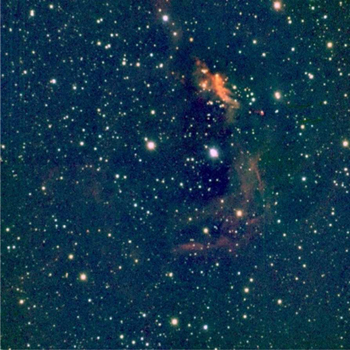
Figure 1. Color-composite image of the SFO 54 region covering 10 × 10 arcmin2 FOV based on the ISPI data. The red, green, and blue colors correspond to K', H, and J bands, respectively.
Download figure:
Standard image High-resolution imageThe point-spread function (PSF)-fitting stellar photometry on these sky-subtracted and combined images was carried out using the find, phot, psf, and allstar routines within DAOPHOT (Stetson 1994). The calibration of the photometry to the standard system was done using the transformation equations:


where the capital JHK are the standard magnitudes of the common stars taken from the Two Micron All Sky Survey (2MASS) catalog, which provides absolute photometry in the J (1.25 μm), H (1.65 μm), and Ks (2.17 μm) bands down to a limiting magnitude of 15.8, 15.1, and 14.3, respectively, with a signal-to-noise ratio greater than 10. The small jhk and Ms and Cs are the instrumental ISPI magnitudes and the transformation coefficients, respectively. In Figure 2, an example of the fit for the transformation coefficients of the ISPI data to the 2MASS data is shown for the sources in the SFO 54 region. The values of these coefficients are given in Table 2, along with the standard errors (∼0.01–0.02 for the zero point (C) and less than 0.03 for the color term (M)). The typical DAOPHOT errors in magnitude as a function of corresponding magnitudes are shown in Figure 3. It can be seen that the errors become large (0.2 mag) for stars fainter than K = 18.5 mag, so the measurements beyond these magnitudes are not reliable and were not used in this study.

Figure 2. Fit for the transformation coefficients for ISPI data using 2MASS data for the sources in the SFO 54 region.
Download figure:
Standard image High-resolution image
Figure 3. Photometric errors as a function of magnitude for all three bands of ISPI data for the sources in the SFO 54 region.
Download figure:
Standard image High-resolution imageTable 2. Color Coefficients and Constants Derived using 2MASS Data for the Calibration of ISPI Data
| ID | N | M1 | C1 | M2 | C2 | M3 | C3 |
|---|---|---|---|---|---|---|---|
| SFO 54 | 220 | 1.013 ± 0.013 | −0.077 ± 0.020 | 0.963 ± 0.026 | 0.420 ± 0.005 | −0.079 ± 0.025 | 0.522 ± 0.012 |
| SFO 55 | 223 | 0.997 ± 0.013 | −0.038 ± 0.020 | 0.996 ± 0.027 | 0.460 ± 0.005 | −0.070 ± 0.025 | 0.532 ± 0.011 |
| SFO 64 | 617 | 1.003 ± 0.008 | −0.086 ± 0.008 | 0.952 ± 0.017 | 0.427 ± 0.005 | −0.078 ± 0.021 | 0.472 ± 0.005 |
| SFO 65 | 671 | 0.993 ± 0.007 | −0.008 ± 0.009 | 0.943 ± 0.026 | 0.449 ± 0.004 | −0.078 ± 0.015 | 0.516 ± 0.006 |
| SFO 68 | 672 | 1.015 ± 0.006 | 0.012 ± 0.008 | 0.967 ± 0.014 | 0.461 ± 0.003 | −0.065 ± 0.016 | 0.501 ± 0.005 |
| SFO 75 | 955 | 0.986 ± 0.006 | 0.079 ± 0.011 | 0.946 ± 0.010 | 0.596 ± 0.002 | −0.064 ± 0.014 | 0.374 ± 0.009 |
| SFO 76 | 993 | 0.981 ± 0.006 | 0.058 ± 0.010 | 0.952 ± 0.011 | 0.559 ± 0.002 | −0.069 ± 0.014 | 0.554 ± 0.008 |
| SFO 79 | 775 | 0.991 ± 0.005 | 0.002 ± 0.010 | 0.970 ± 0.010 | 0.458 ± 0.003 | −0.048 ± 0.011 | 0.499 ± 0.006 |
| Field 1 | 263 | 1.009 ± 0.013 | −0.044 ± 0.014 | 0.985 ± 0.036 | 0.439 ± 0.008 | −0.089 ± 0.034 | 0.490 ± 0.010 |
| Field 2 | 1366 | 0.990 ± 0.004 | −0.065 ± 0.008 | 0.928 ± 0.010 | 0.452 ± 0.002 | −0.052 ± 0.007 | 0.502 ± 0.007 |
Note. "N " represents the total number of the common stars used in the fitting.
Download table as: ASCIITypeset image
Because of the higher number of detected stars in the K and H bands, we used the H − K color to calibrate K magnitude. Therefore, in the final catalog, we only list those stars that are detected in at least K and H bands and found by merging the individual photometric catalog by a search radius of 0.3 arcsec. We aligned the individual frames using the IMALIGN task of IRAF9 with an accuracy better than 0.1 arcsec; our 0.3 arcsec match threshold should match sources for up to 3σ positional errors. In a few cases when there was a second astrometric match, we adopted the closer match for our final merged catalog. We used the K-band position for astrometry of the final catalog. Stars brighter than 10 mag in K are saturated in our observations, so we have taken their respective magnitude from the 2MASS point source catalog. The final catalog contains 2000–15000 sources per field depending on the crowding/nebulosity in the region.
2.2. Spitzer Observations
We used the archived data taken from the Infrared Array Camera (IRAC; Fazio et al. 2004) of the space-based Spitzer telescope at the 3.6, 4.5, 5.8, and 8.0 μm bands. We obtained basic calibrated data (BCD) from the Spitzer data archive for all BRCs except SFO 76. The exposure time of each BCD was 10.4 s and a few hundred BCDs were used for creating a mosaic. Mosaicing in each wavelength was performed by the MOPEX software provided by Spitzer Science Center (SSC). All of our mosaics were built at the native instrument resolution of 1.2 arcsec pixel−1 with the standard BCDs. They were then aligned and trimmed to make a 10.5 × 10.5 arcmin2 box size containing the same area as observed in the ISPI observations. The trimmed sections were used for further analyses. Some of the studied regions were not fully observed in the outer parts (<10% of the whole area) in all four channels of IRAC, but this does not affect our analysis because our region of interest is always closer to the image center containing the H ii regions.
We used the DAOPHOT package in IRAF to detect sources and perform photometry in each of the IRAC mosaics. The FWHM of every detection was measured and all detections with a FWHM > 3.6 arcsec were considered resolved and were removed. The detections were also examined visually in each band to remove non-stellar objects and false detections. In order to avoid source confusion due to crowding, PSF photometry was carried out for all sources. Aperture photometry for well-isolated sources was first done using an aperture radius of 3.6 arcsec with a concentric sky annulus of the inner and outer radii of 3.6 and 8.4 arcsec, respectively. The FWHM of the star's intensity profile was between 2.4–3.6 arcsec in different IRAC bands. As the studied regions are nebulous and sometimes crowded, the inner bright region of the intensity profile (∼1 × FWHM: 3.6 arcsec) of stars was used to derive the aperture magnitude. This will remove some photons from the outer wings of the intensity profile of stars. Because this profile behaves like a Gaussian, at 3 × FWHM radii around ∼99% of star photons can be considered integrated. Therefore, we applied the aperture correction as a difference in aperture magnitudes at these two radii, as has been suggested in the IRAC Handbook for data reduction.10 We adopted the zero-point magnitudes for the standard aperture radius of 12 arcsec (∼3 × FWHM) and background annulus of 12–22.4 arcsec, as 19.670, 18.921, 16.855, and 17.394 in the 3.6, 4.5, 5.8, and 8.0 μm bands, respectively (IRAC data Handbook). The necessary aperture corrections for the PSF photometry were also calculated as a difference between aperture and PSF magnitudes of the selected well-isolated sources, and were applied to the PSF magnitudes of all the sources.
The sources with photometric uncertainties <0.2 mag in each band were considered to be good detections and are used in further analyses. Around 600–1900 sources were detected in 3.6 μm in different regions, with fewer detections at longer wavelengths. This may be because the shorter wavelength channels are more sensitive and less affected by the bright diffuse emission that dominates the 5.0 and 8.0 μm observations. The underlying typical stellar photosphere is also intrinsically fainter at 5.0 and 8.0 μm than at 3.6 and 4.5 μm. The typical magnitude limits of the data in the 3.6, 4.5, 5.8, and 8.0 μm bands having S/N > 5 (error ≤0.2 mag) were found to be ∼16.0, 15.5, 13.0, and 12.8 mag, respectively, but they varied from region to region. The NIR ISPI counterparts of the IRAC sources were then searched for within a radius of 1 arcsec.
3. RESULTS
3.1. Strategy of YSO Identification
The YSOs are usually grouped in an evolutionary sequence representing accreting protostars (Class 0), evolved protostars (Class I), classical T-Tauri stars (CTTSs: Class II), and weak-line T-Tauri stars (WTTSs: Class III; cf. Feigelson & Montmerle 1999). The YSOs of earlier stages are usually deeply buried inside the molecular clouds, hence it is difficult to detect them at optical wavelengths. The most prominent feature of these YSOs is the accreting circumstellar disks. The radiations from the central YSO are more or less absorbed by this circumstellar material and re-emitted in IR. Therefore, with the exception of Class III sources, the YSOs with disks can be probed through their IR excess (compared to normal stellar photospheres).
However, observations of YSOs in SFRs such as Taurus Auriga show a wide dispersion (∼1–10 Myr) in the lifetimes of circumstellar disks (Strom et al. 1989; Haisch et al. 2001; Armitage et al. 2003). Recently, Kraus et al. (2012) studied excess emission in Taurus binaries over NIR to millimeter wavelengths and concluded that the prompt disk dispersal only occurs for a small fraction of single stars, and that ∼80%–90% retain their disks for at least ∼2–3 Myr (but rarely for more than ∼5 Myr). The YSO census based on IR excesses is not complete because it detects only YSOs with an accreting disk. But we are interested in whether our target BRCs have shown star-forming activities in the last couple of Myr, this limitation is small where few YSOs have had sufficient time for their disks to disperse (cf. Hernández et al. 2008; Haisch et al. 2001; Gutermuth et al. 2009, 2011).
The ISPI data along with the Spitzer IRAC data have been used to identify and classify the YSOs associated with the BRCs based on their excess emission in IR by using the following classification schemes.
3.1.1. Step 1: IRAC Four-band YSO Classification Scheme
We applied Step 1 to all sources that are detected in all four IRAC bands. We separated out IR-excess contaminants such as star-forming galaxies, broad-line active galactic nuclei, unresolved shock emission knots, objects that suffer from polycyclic aromatic hydrocarbon (PAH) emissions, and so on by applying constraints in various color spaces (Gutermuth et al. 2009).
To minimize the inclusion of faint extra-galactic contaminants, a brightness limit to IRAC magnitudes was applied. In addition, to discriminate out brighter contaminants, various IRAC color spaces along with magnitude limits have been used. Active star-forming galaxies have a very strong PAH features yielding very red 5.8 and 8.0 μm colors (the 6.2 and 7.7 μm PAH features are much stronger than the 3.3 μm PAH feature; Stern et al. 2005), which can therefore be very well separated out from YSOs using IRAC two-color diagrams (TCDs). The resultant sample will have negligible residual contaminants (Gutermuth et al. 2009). Broad-line active galactic nuclei (AGNs) with MIR colors consistent with YSOs (Stern et al. 2005) can also be separated out from YSOs simply by applying IRAC color selections. In [5.8–8.0] versus [3.6–4.5] TCD, the broad-line AGNs lie along a vertical branch because of the lack of a strong PAH feature at 5.8 and 8.0 μm and the dominating power-law emission peaking at 1.6 μm (Stern et al. 2005). Color/magnitude selection criteria based on Gutermuth et al. (2009) has been used to eliminate these AGNs. Even after applying these cut-offs, we can still expect ∼8 contaminants per square degree (Gutermuth et al. 2009). However, because our FOV is a ∼10 × 10 arcmin square the resultant contaminants will be very low (∼0.2 contaminant per field).
We then isolated YSOs with IR excess from those without IR excess and classified them as Class I or Class II YSOs based on their prominence at longer wavelengths. In Figure 4, we show the [3.6–5.8] versus [4.5–8.0] TCD for all the IRAC sources in all regions studied, where Class I and Class II sources are represented by green star and green open square symbols, respectively. The identified contaminating sources are shown by blue dots.
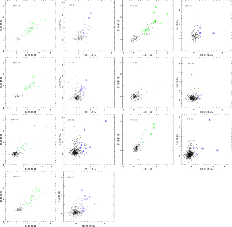
Figure 4. IRAC/2MASS TCDs for the stars in all the regions studied. The YSOs classified as Class I and Class II, based on the color criteria by Gutermuth et al. (2009), are marked using star and square symbols, respectively.
Download figure:
Standard image High-resolution image3.1.2. Step 2: K, [3.6], and [4.5] Three-Band YSO Classification Scheme
Because the studied regions are highly nebulous, the YSO selection based on the IRAC four-band photometry may not be complete, as many sources falling in these regions could not be detected at longer wavelengths due to the saturation of detectors. Therefore, we apply Step 2 to those sources that lack detection at either 5.8 or 8.0 μm, but have NIR detection in the ISPI K band. In Figure 4 we plotted dereddened [3.6–4.5]0 versus [K − 3.6]0 TCD for the sources detected in K, 3.6, and 4.5 μm bands in all regions studied. The following procedure outlined in Gutermuth et al. (2009) was used to classify sources as Class I (blue stars) or Class II (blue squares) YSOs. To estimate the reddening, we used the NIR TCD (cf. Section 3.1.4). Stars with [J − H] color ≥0.6 mag that lie above the CTTS locus or its extension are traced back to the CTTS locus or its extension to get their intrinsic colors. The difference between the intrinsic color and the observed one would give the extinction value. Once we had the extinction value for the individual stars, we generated an extinction map for the whole BRC region. The extinction values in the sky plane were calculated with a resolution of 5 arcsec by taking the mean of the extinction value of stars in a box with a size of 17 arcsec, and then were used to deredden the remaining stars. In the above procedure, we assumed the normal extinction law (RV = 3.1) to back-trace the stars to the CTTS locus. In many SFRs, RV tends to deviate from normal, preferably toward the higher values; for example, RV = 3.7 (Kumar et al. 2014, Carina region), RV = 3.3 (Pandey et al. 2013, NGC 1931), RV = 3.5 (Sharma et al. 2012, NGC 281), and RV = 3.7 (Pandey et al. 2008, Be 59). But the difference between RV = 3.1 and RV = 3.7 would only make a small effect in the near and mid IR region, because for λ > λI, the reddening law can be taken as a universal quantity (Cardelli et al. 1989; He et al. 1995).
3.1.3. Step 3: H, K Two-band YSO Classification Scheme
We applied Step 3 to all the detections in the ISPI H and K bands. The scheme, explained in detail by Kumar et al. (2014), compares the dereddened color–magnitude diagrams (CMDs) of equal area of the studied region and nearby field region (cf. Section 2.1). The dereddened magnitudes and colors were obtained using the extinction map, as discussed in the previous section. In Figure 5, as an example, we plotted the dereddened NIR CMDs, K0 versus (H – K)0, for both SFO 55 and the nearby field region. The blue dashed curve is the outer envelope of the field stars and the thick red curve is the same curve reddened by AV = 5 mag to allow for scattering due to the clumpy nature of the molecular clouds (Kumar et al. 2014). A comparison of the CMDs reveals many sources of (H − K)0 ≳ 0.6 mag in the BRC region, suggesting significant IR excesses in the K band. All the stars with a color " " larger than the RED cut-off curve (shown as a red solid curve in Figure 5; see Kumar et al. 2014 for details) may have an excess emission in the K band and thus can be considered to be probable YSOs (see also Ojha et al. 2004a; Mallick et al. 2012). While these stars are probably dominated by YSOs, they could still be contaminated by variable stars, dusty asymptotic giant branch stars, unresolved planetary nebulae, and background galaxies (Robitaille et al. 2008; Povich et al. 2011). However, because there no stars are located in the field CMD redward of the RED envelope, and neither of these IR-excess sources fall on similar positions of previously identified contaminants (cf. Section 3.1.1), we assume they are probably YSOs with IR excess.

Figure 5. K0/(H − K)0 CMD for (a) stars in the SFO 55 region, (b) stars in the field region, and (c) stars in the SFO 55 region with the marked probable IR-excess sources (circles). The blue dashed curve is the outer envelop of the dereddened field stars and the thick red curve separates the distribution of probable IR-excess stars from that of MS stars.
Download figure:
Standard image High-resolution image3.1.4. Step 4: J, H, K Three-band YSO Classification Scheme
The sources detected in all three ISPI bands (JHK) have been used to further classify YSOs according to their evolutionary stages by using the conventional NIR TCD. In Figure 6, we plotted the NIR TCD for stars in all the regions studied. All the ISPI magnitudes and colors have been converted into the California Institute of Technology (CIT) system.11 The solid and thick dashed curves represent the unreddened MS and giant branch (Bessell & Brett 1988), respectively. The dotted line indicates the locus of unreddened CTTSs (Meyer et al. 1997). All the curves and lines are also in the CIT system. The parallel dashed lines are the reddening vectors drawn from the tip (spectral type M4) of the giant branch ("upper reddening line"), from the base (spectral type A0) of the MS branch ("middle reddening line"), and from the tip of the intrinsic CTTS line ("lower reddening line"). The extinction ratios AJ/AV = 0.265, AH/AV = 0.155, and AK/AV = 0.090 were taken from Cohen et al. (1981). We classified the sources according to three regions in this diagram (cf. Ojha et al. 2004b). The "F" sources are located between the upper and middle reddening lines and are considered to be either field stars (MS stars, giants) or Class III and Class II sources with small NIR excess. "T" sources are located between the middle and lower reddening lines. These sources are considered to be mostly CTTSs (or Class II objects) with large NIR excess. There may be an overlap of Herbig Ae/Be stars in the "T" region (Hillenbrand et al. 1992). "P" sources are those located in the region redward of the lower reddening line, and are most likely Class I objects (protostellar-like objects; Ojha et al. 2004b). It is worthwhile to mention also that Robitaille et al. (2006) have shown that there is a significant overlap between protostars and CTTSs. All sources were designated as CTTSs if they satisfy the criteria that they fall in the "T" region of the NIR TCD (Figure 6) and lie redward of the blue dotted cut-off line of the dereddened CMD (cf. Figure 5); they are shown as open triangles in Figure 6. We also plotted the previously identified probable IR-excess sources (open circles) with a J band detection. Most of these sources are located in the "P" region in Figure 6, which means that they are most likely Class I objects.
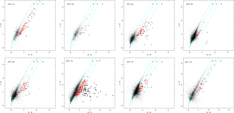
Figure 6. NIR TCD for the stars in all regions studied. The continuous and thick dashed curves represent the unreddened MS and giant branch (Bessell & Brett 1988), respectively. The dotted line indicates the loci of unreddened CTTSs (Meyer et al. 1997). The parallel dashed lines are the reddening vectors drawn from the tip (spectral type M4) of the giant branch (left reddening line), from the base (spectral type A0) of the MS branch (middle reddening line), and from the tip of the intrinsic CTTS line (right reddening line). The crosses on the reddening vectors show an increment of AV = 5 mag. The sources marked with open triangles and circles are identified CTTSs and probable IR-excess sources, respectively.
Download figure:
Standard image High-resolution image3.2. The YSO Sample and its Completeness
We have thus identified and classified 44 to 433 YSOs in our BRCs based on their excess emission in IR. In total 1347 YSOs were identified, out of which 790 are Class I protostars. We have made a catalog of the YSOs for each BRC identified in the present study. Table 3 lists a sample of these YSOs, along with their positions, magnitudes at various bands, and the flags for the scheme used to classify them. A complete table is available in electronic form only.
Table 3. Sample of YSOs Identified in the Present Study on the Basis of their Excess IR-emission using CTIO/Spitzer Data
| Name | α2000 | δ2000 | J ± σ | H ± σ | K ± σ | 3.6 ± σ | 4.5 ± σ | 5.8 ± σ | 8.0 ± σ | Commenta |
|---|---|---|---|---|---|---|---|---|---|---|
| (BRC_ID) | (h:m:s) | (o:':'') | (mag) | (mag) | (mag) | (mag) | (mag) | (mag) | (mag) | |
| SFO54_1 | 08:35:40.30 | 40:40:07.2 | 9.704 ± 0.017 | 8.880 ± 0.019 | 8.128 ± 0.015 | 7.191 ± 0.110 | 6.818 ± 0.070 | 6.135 ± 0.018 | 5.430 ± 0.046 | 2 |
| SFO54_2 | 08:35:32.82 | 40:38:36.2 | ⋯ | 11.049 ± 0.033 | 9.421 ± 0.022 | 7.890 ± 0.061 | 7.385 ± 0.036 | 6.926 ± 0.019 | 6.436 ± 0.023 | 2, 6 |
| SFO54_3 | 08:35:30.95 | 40:38:26.7 | ⋯ | 13.023 ± 0.067 | 9.865 ± 0.033 | ⋯ | ⋯ | ⋯ | ⋯ | 6 |
| SFO54_4 | 08:35:22.56 | 40:38:50.2 | 12.684 ± 0.024 | 11.081 ± 0.051 | 9.927 ± 0.039 | 8.357 ± 0.079 | 7.842 ± 0.035 | 7.365 ± 0.022 | 6.574 ± 0.022 | 2, 5 |
| SFO54_5 | 08:35:31.03 | 40:38:22.3 | 14.586 ± 0.004 | 12.171 ± 0.005 | 10.523 ± 0.016 | ⋯ | ⋯ | ⋯ | ⋯ | 5 |
| SFO54_6 | 08:35:17.76 | 40:38:23.4 | 12.290 ± 0.006 | 11.420 ± 0.006 | 10.932 ± 0.007 | 10.499 ± 0.068 | 10.097 ± 0.051 | 9.795 ± 0.031 | 9.087 ± 0.042 | 2 |
| SFO54_7 | 08:35:32.80 | 40:38:15.5 | 13.628 ± 0.002 | 11.964 ± 0.002 | 11.095 ± 0.004 | 9.773 ± 0.086 | 9.222 ± 0.050 | 8.507 ± 0.036 | 7.732 ± 0.023 | 2 |
| SFO54_8 | 08:35:34.65 | 40:37:27.3 | 15.692 ± 0.009 | 12.856 ± 0.003 | 11.156 ± 0.006 | 9.573 ± 0.068 | 9.006 ± 0.020 | 8.486 ± 0.034 | 7.597 ± 0.017 | 2, 5 |
| SFO54_9 | 08:35:42.10 | 40:38:05.1 | 13.125 ± 0.002 | 12.003 ± 0.002 | 11.227 ± 0.006 | 10.383 ± 0.070 | 10.400 ± 0.039 | 10.311 ± 0.042 | 10.220 ± 0.031 | 5 |
| SFO54_10 | 08:35:25.92 | 40:38:58.3 | 13.164 ± 0.003 | 12.040 ± 0.002 | 11.419 ± 0.002 | 10.385 ± 0.042 | 9.887 ± 0.035 | 9.362 ± 0.038 | 8.462 ± 0.025 | 2 |
Notes. Their respective magnitudes and photometric errors are also given. The last column gives the information about the scheme used in their classification.
a1—Class I (Through Spitzer data), 2—Class II (Through Spitzer data), 3—Class I (Through CTIO/Spitzer data), 4—Class II (Through CTIO/Spitzer data), 5—Class II (Through CTIO data), 6—Class I (Through CTIO data).Only a portion of this table is shown here to demonstrate its form and content. A machine-readable version of the full table is available.
Download table as: DataTypeset image
To understand the level of star formation at present or in the past in our BRCs, it is important to know the completeness limits in terms of masses for the sample of YSOs identified in each region. The photometric data may be incomplete due to various reasons (e.g., background nebulosity, crowding of stars, the detection limit, etc). For the current sample, the YSOs are identified if they are detected in at least two Spitzer IRAC channels (3.6 and 4.5 μm, Steps 1 and 2) or if they are detected in two ISPI H and K bands (Steps 3 and 4). In Figure 7 (top left panel), we plotted IRAC 3.6 μm mag versus ISPI K mag for the sources detected in the SFO 54 region. From the figure, it is clear that the faintest source in 3.6 μm band (∼16.5 mag) corresponds to those of K ∼ 15.5 mag. The K band has yielded much fainter detections (∼18.5 mag), therefore the completeness of our photometric data taken from ISPI will dictate the completeness of the current sample of YSOs.

Figure 7. (Top Left): comparison between the ISPI K band and Spitzer 3.6 μm photometry. (Top Right): completeness factor of the photometry in different ISPI bands in the SFO 54 region. Black dashed, dotted green, and solid red curves are the smoothened bezier curves for the data points for completeness in the J, H, and K bands, respectively. KF (dotted gray curve) and KC (solid black curve) represent similar curves in the K band for the field and SFO 64 regions, respectively. (Lower Panel): K vs. (H − K) CMD for the YSOs detected in the SFO 54 region along with the theoretical MS isochrone of 2 Myr (Z = 0.02, solid black curve) by Marigo et al. (2008), and the PMS isochrones of ages 1 and 5 Myr (solid red and solid blue curves) by Siess et al. (2000; for masses >1.2 M⊙) and Baraffe et al. (1998; for masses <1.2 M⊙), corrected for distance and foreground reddening. The symbols are same as in Figures 4–6. Slanting parallel dashed lines show the reddening vectors for PMS stars of different masses. The dotted and solid broken lines represent the 90% and 50% completeness limits for the data, respectively. See Section 3.2 for details.
Download figure:
Standard image High-resolution imageTo determine the completeness factor (CF) for ISPI data, we used the ADDSTAR routine of DAOPHOT II. This method has been used by various authors (see Sharma et al. 2007, 2008, and references therein). Briefly, the method consists of randomly adding artificial stars of known magnitudes and positions into the original frame. The frames are reduced with the same procedure used for the original frame. The ratio of the number of stars recovered to those added in each magnitude interval gives the CF as a function of magnitude. The luminosity distribution of artificial stars is chosen in such a way that more stars are inserted into the fainter magnitude bins. In all, about 15% of the total stars are added so that the crowding characteristics of the original frame do not change significantly (see Sagar & Richtler 1991). As an example, the CF for the SFO 54 region (distance = 0.95 kpc) is given in the top right panel of Figure 7 for different ISPI bands. In the same panel, we also plotted the K-band CFs for a nearby field region (shown by the gray dotted curve "KF") as well as for the SFO 64 region (distance = 2.7 kpc, shown by the black solid curve "KC"), representing a field free from nebulosity and that of higher crowding, respectively. Higher crowding, in the case of SFO 64 can be attributed to its intrinsic property or its farther distance. The field region has the highest completeness because of the lack of nebular backgrounds. Out of SFO 64 and SFO 54, which both have a similar level of nebulosity, SFO 64 shows a lower CF because of its larger distance and/or higher crowding.
In the lower panel of Figure 7, we plotted the (H − K) versus K CMD for the SFO 54 region, along with the theoretical MS isochrone of 2 Myr (Z = 0.02) by Marigo et al. (2008) and the pre-main sequence (PMS) isochrones of age 1 and 5 Myr by Siess et al. (2000; for mass >1.2 M⊙) and Baraffe et al. (1998; for mass <1.2 M⊙), all corrected for the distance (cf. Urquhart et al. 2009) and the foreground expected reddening ( 0.15 × D, where D is the distance in kpc; Indebetouw et al. 2005). The slanting parallel dashed lines represent the reddening vectors for PMS stars of different masses. The dotted and solid broken lines represent the 90% and 50% completeness limits for the data as inferred from the CF calculated earlier. We have taken into account the effect of color (H − K) on the completeness limit of this CMD. We can easily see that the 90% and 50% completeness limits correspond to ∼0.04 M⊙ and ∼0.03 M⊙ YSOs, respectively. However, the photometric errors at this level should be higher (±0.1 mag to ±0.2 mag), therefore, the corresponding errors in the derived mass should be of the order of ∼±0.02 M⊙ to ±0.03 M⊙. The 90% and 50% completeness limits for the YSOs embedded deeply in the molecular cloud (corresponding to the peak AK value taken from Table 5) are considered to be ∼0.15 ± 0.03 M⊙ and ∼0.08 ± 0.04 M⊙, respectively. In the last column of Table 1, we have given the 90% completeness limit for YSOs corrected for the foreground and peak (including the foreground) reddening for all the studied regions.
The PMS isochrones were used to derive the CF for the sample of YSOs in terms of mass. The errors in the mass of the YSOs quoted above comes mainly from the large photometric errors at faint levels. In the H − K versus K diagram (Figure 7 lower panel), the PMS isochrones are almost vertical; therefore any change of age in the lower mass regime would shift the isochrones in the vertical direction (magnitude axis), and typically it would cause a 0.02 M⊙ difference for the age difference of 4 Myr (cf. Figure 7. Lower Panel). From Figures 6 and 7 and similar corresponding figures for the rest of our BRCs we find that all of them are regions of recent star formation harboring YSOs of various evolutionary stages from Class 1 (protostars) to at least Class II (CTTSs), leading to the lower error values in mass determination of YSOs due to their comparatively smaller age spreads.
3.3. Distribution of Molecular Cloud around the BRCs
To study the relationship between the distribution of YSOs and the molecular clumps in the regions, we derived AK extinction maps using the (H − K) colors of the MS stars (cf. Gutermuth et al. 2011). This map was also used to quantify the amount of extinction within each subregion of the studied BRCs and to characterize the structures of the molecular clouds within each subregion (Gutermuth et al. 2009, 2011; Jose et al. 2013). The sources showing excess emission in IR can lead to overestimation of extinction values in the derived maps. The excess emission can be of the order of ∼0.25 mag in H − K color (Pandey et al. 2008; Chauhan et al. 2011; Sharma et al. 2012), which corresponds to the overestimation of the AK value by ∼0.4 mag. This increases the cloud-mass estimate that we are going to derive later (Section 4.2.7). Therefore, to improve the quality of the extinction maps the candidate YSOs and probable contaminating sources (cf. Section 3.1) must be excluded from the stars used. In order to determine the mean value of AK, we used the nearest neighbor (NN) method as described in detail in Gutermuth et al. (2005, 2009). Briefly, at each position in a uniform grid of 5 arcsec, we calculated the mean value of the (H − K) colors of the five nearest stars. The sources deviating above 3σ were excluded to calculate the final mean color of each point. To convert (H − K) color excesses into AK we used the relation AK = 1.82 × ((H − K)obs − (H − K)int). This is derived from the reddening law by Flaherty et al. (2007). We assumed (H − K)int = 0.2 mag to be an average intrinsic color for all stars in the young clusters (see. Allen et al. 2008; Gutermuth et al. 2009). Of course, the intrinsic color depends on the spectral type (i.e., mass of the MS stars), so this assumption introduces errors in reddening estimation. But this effect will be small, as shown in Figure 7 (bottom panel). The MS for stars for the whole mass/spectral range is almost vertical. The standard deviation in the H − K color is of the order of 0.1 mag, which corresponds to the error of ∼0.1 AK in the extinction map. To eliminate the foreground contribution in the extinction measurement, we used only those stars with AK > 0.15 × D, where D is the distance in kpc (Indebetouw et al. 2005) to generate the extinction map. The extinction maps smoothened to a resolution of 5 arcsec and reaching down, up to AK ∼ 2.8 mag were generated for all the regions studied. However, the derived AK values should be considered a lower limit because the sources with higher extinction may not be detected in our study. As an example, we show in Figure 8 (left panel) the derived extinction map for the SFO 54 region.

Figure 8. (Left Panel): extinction map smoothed to a resolution of 5 arcsec for the SFO 54 region. The contours are drawn with a step size of AK = 0.1 mag starting from the lowest contour approximately equal to the mean AK value for the selected active region (cf. Table 5). (Right Panel): surface isodensity contours of YSOs detected in the same region with the same resolution. The contours are shown with a step size of 2 stars arcmin−2 with the lowest contour approximately equal to the mean number density in the arcmin square for the selected active region (cf. Table 5). Both maps have an FOV of ∼10 × 10 arcmin2.
Download figure:
Standard image High-resolution image3.4. Spatial Distribution of YSOs in the Region
By analyzing the stellar density distribution morphology in relation to the molecular cloud structure, observational analyses can address the link between star formation, gas expulsion, and the dynamics of the clusters, as well as how these processes guide the evolution of young clusters (Gutermuth et al. 2005). To study the density distribution of YSOs in the region, we generated their surface density maps using the NN method as described by Gutermuth et al. (2005). We took the radial distance necessary to encompass the fifth nearest YSOs and computed the local surface density (cf. Figure 8, right panel) in a grid size of 5 arcsec. To facilitate comparisons between the stellar density and the gas column density, we adopted grids that were identical to the grid size of the extinction map for each region.
The spatial distribution of YSOs in a region can also be analyzed by deriving the typical spacing between them and comparing this spacing to the Jeans fragmentation scale for a self-gravitating medium with thermal pressure (Gomez et al. 1993). We measure the projected distance from each YSO to its nearest YSO neighbor (NN2), as well as to its fifth nearest YSO neighbor (NN6; the radial distance from each source, such that a circular area of that radius centered on the source contains the nearest five neighbors; i.e., a total of six YSOs), and plotted their histograms with a bin size of 0.02 pc in Figure 9 for all the studied BRCs. All the histograms show a major peak in their distribution along with a couple of smaller peaks indicating groupings or subgroupings in the regions.
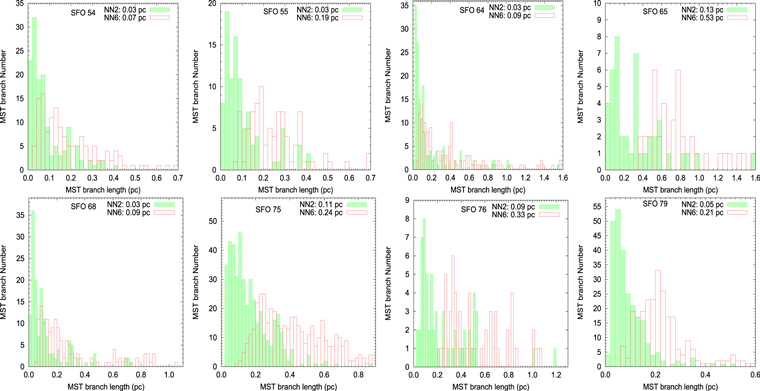
Figure 9. Histograms of the nearest neighbor (NN) lengths for the YSOs in the studied regions with a bin size of 0.02 pc. The red and green histograms represent NN6 (the projected distance from each YSO to its fifth nearest YSO neighbor) and NN2 (the projected distance from each YSO to its nearest YSO neighbor), respectively (see the text for detail).
Download figure:
Standard image High-resolution image3.5. Extraction of YSO's Cores Embedded in the Molecular Cloud
All the studied BRCs contain a number of subgroups or cores of YSOs (cf. Figures 10–17, top left panels), presumably due to fragmentation of the molecular cloud. The physical parameters of these cores, which might have formed in a single star-forming event, play a very important role in the study of star formation. Gutermuth et al. (2009) applied an empirical method based on the minimal sampling tree (MST) technique to a sample of 36 young stellar clusters to isolate groupings (cores) from the more diffuse distribution of YSOs in nebulous regions. This method effectively isolates the substructures without any type of smoothing (e.g., Cartwright & Whitworth 2004; Schmeja & Klessen 2006; Bastian et al. 2007, 2009; Gutermuth et al. 2009). The subgroups detected in this way have no bias regarding the shapes of the distribution, and preserve the underlying geometry of the distribution (Gutermuth et al. 2009). In Figures 10–17 (bottom left panels) we plotted the derived MSTs for the YSOs in the BRC regions studied. The different color dots and lines are the positions of the YSOs and the MST branches, respectively. A close inspection of these figures reveals that all the regions exhibit inhomogeneous structures and there is one major and several other concentrations of YSOs distributed throughout the regions.
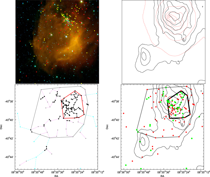
Figure 10. (Top Left) Color-composite image of the SFO 54 region obtained by combining the K (blue), 3.6 μm (green), and 8.0 μm (red) images for an area of ∼10 × 10 arcmin2. The identified YSOs (Class I: yellow dots, Class II: red dots) are also plotted. (Top Right): isodensity contours for the YSO distribution (red dotted contours) and the reddening map (black solid contours) for the same region. The contour levels are the same as in Figure 8. (Bottom Left): minimal spanning tree (MST) for the identified YSOs in the same region along with the convex hull. The black dots connected with solid lines and gray dots connected with purple dotted lines are the branches smaller than the critical length for the cores and the active region, respectively. The identified core and the active region are encircled with red and gray solid lines, respectively. (Bottom Right): spatial correlation between the molecular material inferred from the extinction map (thin black contours) and the distribution of YSOs along with the identified cores and active regions (thick black and thin gray lines, respectively).
Download figure:
Standard image High-resolution image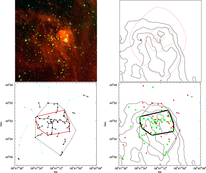
Figure 11. Same as Figure 10, but for SFO 55.
Download figure:
Standard image High-resolution image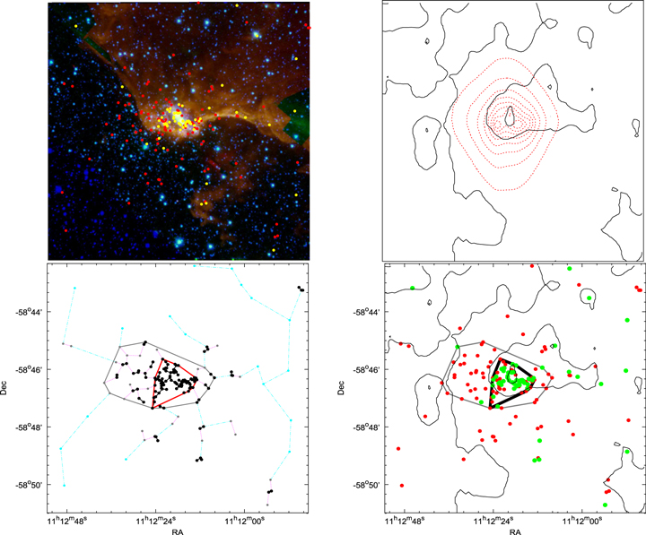
Figure 12. Same as Figure 10, but for SFO 64.
Download figure:
Standard image High-resolution image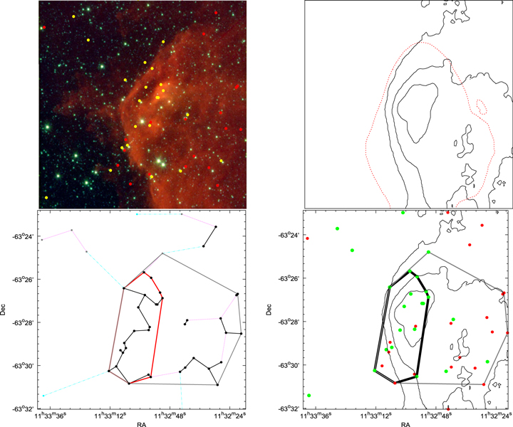
Figure 13. Same as Figure 10, but for SFO 65.
Download figure:
Standard image High-resolution image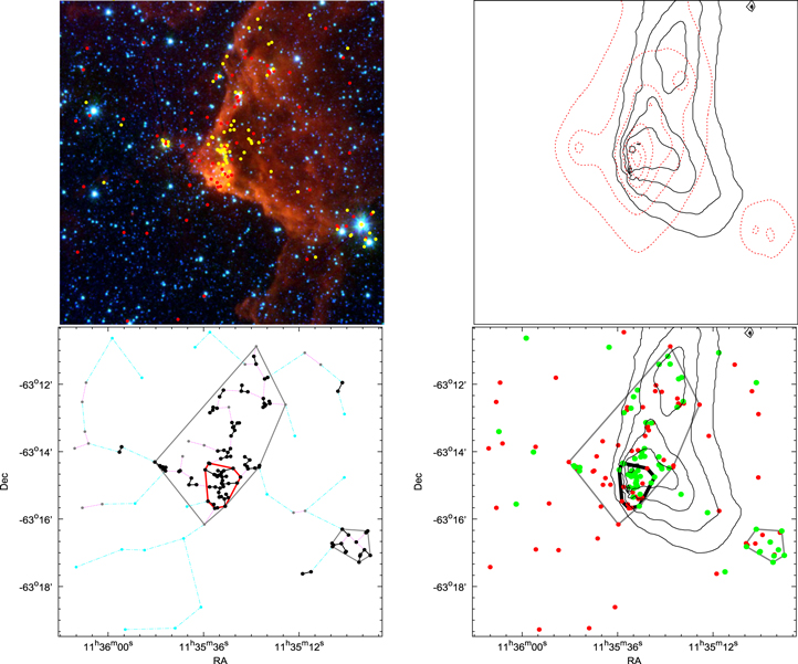
Figure 14. Same as Figure 10, but for SFO 68.
Download figure:
Standard image High-resolution image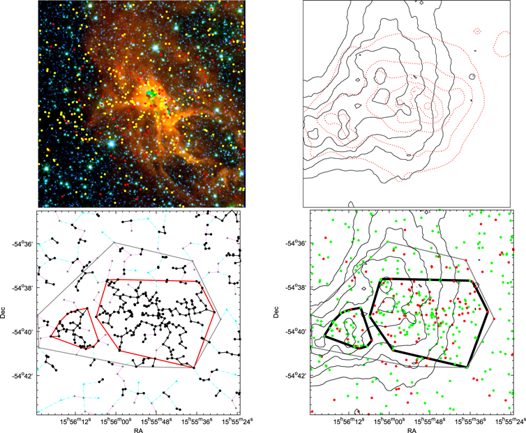
Figure 15. Same as Figure 10, but for SFO 75.
Download figure:
Standard image High-resolution image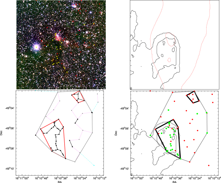
Figure 16. Same as Figure 10, but for SFO 76.
Download figure:
Standard image High-resolution image
Figure 17. Same as Figure 10, but for SFO 79.
Download figure:
Standard image High-resolution imageIn order to isolate the substructures, we have to adopt a surface density threshold expressed by a critical branch length. In Figure 18 we plotted histograms between MST branch lengths and MST branch numbers for the YSOs. From this plot, it is clear that they have a peak at small spacings and a relatively long tail toward large spacings. These peaked distance distributions typically suggest a significant subregion (or subregions) above a relatively uniform, elevated surface density. By adopting an MST length threshold, we can isolate those sources that are closer than this threshold, yielding populations of sources that make up local surface density enhancements. To obtain a proper threshold distance, we used a similar approach to that demonstrated by Gutermuth et al. (2009). In Figure 18, we also plotted the cumulative distribution function (CDF) for the branch length of YSOs for MST. In this distribution, we can see three line segments: a steep-sloped segment at short spacings, a transition segment that approximates curved character of the intermediate length spacings, and a shallow-sloped segment at long spacings (cf. Gutermuth et al. 2009). Typically, most of the sources are found in the steep segment where the spacings are small (e.g., in a core of the stellar distribution). Therefore, to isolate the core region in the BRCs, we fit by two true lines in a shallow and steep segment of the CDF and extended them to connect together. We adopted the intersection point between these two lines as the MST critical branch length, as shown in Figure 18 (see also, Gutermuth et al. 2009). The BRC cores were then isolated from the lower density distribution by clipping MST branches longer than the critical length found above. Similarly, we enclosed all YSOs associated with the BRC by selecting the point where the curved transition segment meets the shallow-sloped segment at longer spacings. We call this region as BRCs active region where recent star formation took place or contains YSOs moved out from the cores due to dynamical evolution. Black dots and black MST connections in Figures 10–17 (bottom left panels) represent the more closely spaced YSOs than the critical length. In this way we can very easily pick up the major groupings of the YSOs along with some other subgroupings scattered in the regions. We plotted the respective convex hull (cf. Gutermuth et al. 2009) for these cores and for the whole active region in Figures 10–17, lower panels (solid red and solid gray lines, respectively). The physical details of these subgroups (cores) and the active regions are given in Tables 4–6. The median value of the critical branch lengths for the cores and the active regions are 0.18 pc and 0.30 pc, respectively.
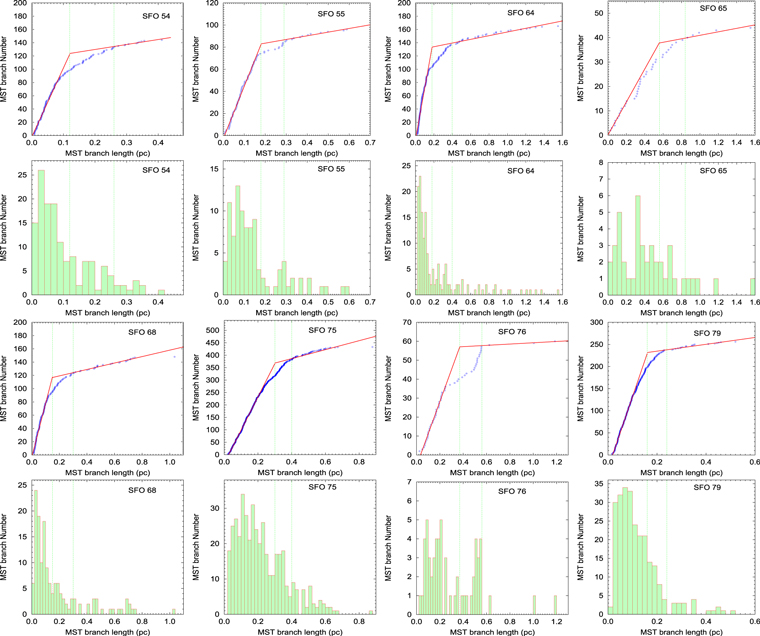
Figure 18. Cumulative distribution functions (CDFs) and histograms of the MST branch lengths used for critical length analyses of the YSOs. The CDF plots have sorted length values on the horizontal axis and a rising integer counting index on the vertical axis. The red solid line is a two-line fit to the CDF distribution. The inner and outer vertical green lines stand for critical lengths obtained for the core and the active region, respectively.
Download figure:
Standard image High-resolution imageTable 4. Center Coordinates of the Identified Cores and Active Regions along with the Total Number of the YSOs, and their Distribution as a Function of their Evolutionary Status
| Name | α2000 | δ2000 | N | Class | Class | Fraca |
|---|---|---|---|---|---|---|
| (h:m:s) | (o:':'') | I | II | (%) | ||
| Cores | ||||||
| SFO 54 C1 | 08:35:28.6 | −40:38:30 | 81 | 36(3) | 45(22) | 44(12) |
| SFO 55 C1 | 08:41:13.5 | −40:52:11 | 55 | 37(4) | 18(12) | 67(25) |
| SFO 64 C1 | 11:12:19.1 | −58:46:23 | 78 | 41(1) | 37(12) | 53(8) |
| SFO 65 C1 | 11:33:00.4 | −63:28:16 | 21 | 15(0) | 6(2) | 71(0) |
| SFO 68 C1 | 11:35:31.7 | −63:14:58 | 35 | 23(2) | 12(2) | 66(50) |
| SFO 68 C2 | 11:34:58.5 | −63:16:45 | 17 | 10(0) | 7(0) | 59(−) |
| SFO 75 C1 | 15:55:49.2 | −54:39:15 | 175 | 114(4) | 61(8) | 65(33) |
| SFO 75 C2 | 15:56:12.3 | −54:39:57 | 42 | 34(0) | 8(0) | 81(−) |
| SFO 76 C1 | 16:10:39.1 | −49:06:53 | 30 | 21(0) | 9(0) | 70(−) |
| SFO 76 C1 | 16:10:25.5 | −49:02:55 | 8 | 0(0) | 8(0) | −(−) |
| SFO 79 C1 | 16:40:01.3 | −48:51:43 | 84 | 53(8) | 31(15) | 63(35) |
| SFO 79 C2 | 16:39:46.3 | −48:51:05 | 11 | 10(0) | 1(1) | 91(0) |
| SFO 79 C3 | 16:40:11.3 | −48:48:59 | 25 | 17(2) | 8(4) | 68(33) |
| Active regions | ||||||
| SFO 54 A | 08:35:31.1 | −40:38:43 | 128 | 48(4) | 80(45) | 38(8) |
| SFO 55 A | 08:41:13.0 | −40:52:27 | 78 | 49(6) | 29(19) | 63(24) |
| SFO 64 A | 11:12:21.1 | −58:46:20 | 115 | 45(2) | 70(39) | 39(5) |
| SFO 65 A | 11:32:49.4 | −63:28:23 | 35 | 19(0) | 16(5) | 54(0) |
| SFO 68 A | 11:35:30.8 | −63:13:59 | 97 | 50(3) | 47(11) | 52(21) |
| SFO 75 A | 15:55:54.4 | −54:39:16 | 269 | 181(4) | 88(10) | 67(29) |
| SFO 76 A | 16:10:33.9 | −49:05:56 | 56 | 26(0) | 30(0) | 46(−) |
| SFO 79 A | 16:40:00.6 | −48:51:31 | 219 | 155(12) | 64(35) | 71(26) |
Notes. The numbers in bracket represent the YSOs classified by using the Spitzer IRAC data.
aClass 1/(Class 1 + Class II).Download table as: ASCIITypeset image
Table 5. Properties of the Identified Cores and Active Regions
| Name | Rhull | Rcir | Aspect | ρmean | ρpeak | MST | NN2 |

|

|

|

|
Q | J | Dcrit. |
|---|---|---|---|---|---|---|---|---|---|---|---|---|---|---|
| (pc) | (pc) | Ratio | (pc−2) | (pc−2) | (pc) | (pc) | (mag) | (mag) | (M⊙) | (M⊙) | (pc) | (pc) | ||
| Cores | ||||||||||||||
| SFO 54 C1 | 0.40 | 0.45 | 1.28 | 163.21 | 1330.4 | 0.04 | 0.03 | 1.32 | 2.34 | 131.3 | 125.3 | 0.75 | 0.30 | 0.12 |
| SFO 55 C1 | 0.58 | 0.70 | 1.49 | 52.83 | 454.1 | 0.07 | 0.06 | 1.09 | 1.89 | 215.3 | 189.5 | 0.64 | 0.46 | 0.18 |
| SFO 64 C1 | 0.58 | 0.73 | 1.59 | 75.11 | 386.9 | 0.06 | 0.05 | 0.61 | 1.81 | 127.2 | 37.2 | 0.65 | 0.52 | 0.18 |
| SFO 65 C1 | 1.02 | 1.29 | 1.58 | 6.38 | 17.1 | 0.20 | 0.12 | 0.65 | 1.97 | 296.9 | 168.8 | 0.59 | 0.98 | 0.56 |
| SFO 68 C1 | 0.30 | 0.34 | 1.22 | 120.36 | 693.6 | 0.06 | 0.04 | 1.36 | 2.56 | 68.5 | 63.5 | 0.75 | 0.27 | 0.15 |
| SFO 68 C2 | 0.30 | 0.28 | 0.89 | 61.15 | 132.0 | 0.09 | 0.03 | 0.49 | 1.12 | 19.8 | 2.6 | 0.66 | 0.46 | 0.15 |
| SFO 75 C1 | 1.85 | 2.22 | 1.43 | 16.20 | 209.7 | 0.13 | 0.10 | 1.06 | 2.54 | 2416.1 | 2015.7 | 0.69 | 0.84 | 0.30 |
| SFO 75 C2 | 0.81 | 0.83 | 1.07 | 20.61 | 86.4 | 0.11 | 0.09 | 1.50 | 2.73 | 525.9 | 517.5 | 0.67 | 0.52 | 0.30 |
| SFO 76 C1 | 0.77 | 1.04 | 1.81 | 16.06 | 53.6 | 0.16 | 0.10 | 1.07 | 2.36 | 372.7 | 316.8 | 0.55 | 0.57 | 0.37 |
| SFO 76 C1 | 0.37 | 0.36 | 0.96 | 18.76 | 26.5 | 0.19 | 0.15 | 0.56 | 0.86 | 27.0 | 2.2 | 0.71 | 0.65 | 0.37 |
| SFO 79 C1 | 0.61 | 0.73 | 1.45 | 331.86 | 258.0 | 0.07 | 0.04 | 1.55 | 2.79 | 353.6 | 349.8 | 0.58 | 0.39 | 0.16 |
| SFO 79 C2 | 0.18 | 0.24 | 1.69 | 104.62 | 150.0 | 0.07 | 0.06 | 1.64 | 2.20 | 21.5 | 21.5 | 0.62 | 0.23 | 0.16 |
| SFO 79 C3 | 0.36 | 0.45 | 1.55 | 60.39 | 136.2 | 0.11 | 0.05 | 1.47 | 2.71 | 92.4 | 91.2 | 0.67 | 0.34 | 0.16 |
| Active regions | ||||||||||||||
| SFO 54 A | 0.87 | 1.05 | 1.44 | 53.06 | 1330.4 | 0.06 | 0.05 | 0.91 | 2.34 | 451.8 | 299.0 | 0.85 | 0.57 | 0.26 |
| SFO 55 A | 0.85 | 1.00 | 1.39 | 34.37 | 454.1 | 0.09 | 0.06 | 1.03 | 1.89 | 465.3 | 393.1 | 0.70 | 0.57 | 0.29 |
| SFO 64 A | 1.15 | 1.52 | 1.74 | 27.75 | 386.9 | 0.09 | 0.06 | 0.42 | 1.81 | 348.3 | 63.6 | 0.80 | 0.97 | 0.40 |
| SFO 65 A | 1.62 | 1.68 | 1.07 | 4.24 | 17.1 | 0.32 | 0.15 | 0.54 | 1.97 | 800.1 | 200.3 | 0.69 | 1.21 | 0.84 |
| SFO 68 A | 0.88 | 1.35 | 2.36 | 39.72 | 693.6 | 0.07 | 0.05 | 0.76 | 2.56 | 391.3 | 255.6 | 0.59 | 0.63 | 0.30 |
| SFO 75 A | 2.63 | 3.22 | 1.50 | 12.42 | 209.7 | 0.16 | 0.11 | 1.12 | 2.84 | 5286.7 | 4601.4 | 0.71 | 0.97 | 0.40 |
| SFO 76 A | 1.66 | 1.87 | 1.26 | 6.47 | 53.6 | 0.19 | 0.15 | 0.67 | 2.36 | 1108.5 | 427.3 | 0.72 | 1.06 | 0.56 |
| SFO 79 A | 1.35 | 1.66 | 1.52 | 38.30 | 258.0 | 0.09 | 0.06 | 1.40 | 2.80 | 1683.8 | 1619.9 | 0.67 | 0.61 | 0.24 |
Note. The hull and circle radius along with the aspect ratio are given in columns 2, 3, and 4, respectively. Columns 5 and 6 represent the mean and peak stellar density obtained using the isodensity contours. Columns 7 and 8 are the mean MST branch length and NN distances, respectively. The mean and peak extinction values are given in columns 9 and 10, respectively. Column 11 represents the cloud mass in the convex hull derived using the extinction maps. Column 12 represents the mass of the dense cloud with AK greater than 0.8 mag. Columns 13–15 represent the Q value, Jeans length, and critical branch length for MST, respectively.
Download table as: ASCIITypeset image
Table 6. Median Averaged Parameters of All the Cores and Active Region
| Properties | Core | Active region |
|---|---|---|
| Fraction of Class I sources (%) | 66(33) | 52(21) |
| NN2(Class I) (pc) | 0.07 | 0.07 |
| NN2(Class II) (pc) | 0.10 | 0.11 |
A (mag) (mag) |
1.3 | 1.1 |
A (mag) (mag) |
1.0 | 0.8 |
| Number of YSOs | 35 | 97 |
| Rhull (pc) | 0.58 | 1.15 |
| Aspect Ratio | 1.45 | 1.44 |
| Mean number density (pc−2) | 60 | 28 |
| Peak number density (pc−2) | 150 | 258 |
| AK (mag) | 1.1 | 0.8 |
| Peak AK(mag) | 2.3 | 2.3 |
| Cloud mass (M⊙) | 131 | 465 |
| Dense cloud mass (M⊙) | 125 | 299 |
| MST branch length (pc) | 0.09 | 0.09 |
| Structural Q parameter | 0.66 | 0.70 |
| Structural Q parameter(Class I) | 0.68 | 0.64 |
| Structural Q parameter(Class II) | 0.72 | 0.81 |
| Jeans Length (pc) | 0.46 | 0.63 |
| Star formation efficiency (%) | 12 | 6 |
Note. The figures in brackets represent the numbers of the YSOs classified using the Spitzer IRAC data.
Download table as: ASCIITypeset image
4. DISCUSSION
4.1. General Trends in the Spatial Distributions
In this section, we investigate the distribution of the YSOs, their separation, and their relation to the associated molecular clouds as a function of their evolutionary status.
4.1.1. YSOs and their Association with the Surrounding Molecular Cloud
The identification of YSOs (cf. Section 3) in a sample of eight BRCs that are classified as triggered by Urquhart et al. (2009) reveals recent star formation in them. A newer observational characterization of the relationship between the spatial distribution of the YSOs and their associated cloud material is vital to understand the nature of their spatial distribution, constrain the model of star formation, and ascertain the underlying physics (e.g., Bate & Bonnell 2005; Krumholz & Tan 2007; Myers 2009; Gutermuth et al. 2011). We studied the spatial distribution of the YSOs in and around the BRCs by superimposing them on the ∼10' × 10' color-composite image obtained from the 8.0 μm (red), 3.6 μm (green), and K (blue) band images (Figures 10–17 (top left panels)). The yellow and red dots are Class I and Class II objects, respectively. The distribution of gas and dust as seen by the MIR emissions, along with several concentrations of YSOs can be easily seen in the images. The distribution of YSOs reveals that a majority of Class I sources belong generally to these concentrations, whereas the comparatively older population (i.e., Class II objects) is rather randomly distributed throughout the region.
Star formation usually takes place inside the dense cores of molecular clouds and the YSOs often follow the clumpy structures of their parental molecular clouds (see e.g., Gomez et al. 1993; Lada et al. 1996; Motte et al. 1998; Allen et al. 2002; Gutermuth et al. 2005, 2008; Teixeira et al. 2006; Winston et al. 2007). The IR extinction maps can be used to represent the column density distribution of the molecular cloud associated with BRCs (cf. Gutermuth et al. 2009; Jose et al. 2013). We compared the isodensity contours of YSOs with the extinction maps (Figures 10–17; top right panels), and found that most of the YSOs are distributed in groups in the regions of detectable extinction. Gutermuth et al. (2011) also found similar trends in eight nearby molecular clouds. They reported a power-law correlation between the local surface densities of YSOs and the column density of gas (as traced by NIR extinction), agreeing with the prediction of the thermal fragmentation of a sheet-like isothermal layer. If we compare the extinction contours with the IRAC 8.0 μm images (Figures 10–17; top left panels), they roughly follow one another's distribution, except in one or two BRCs, but the peaks do not match well. The IRAC 8.0 μm band includes the PAH emission and its intensity would be the strongest in the photodissociation region (PDR), which faces the ionizing source. The extinction contours, on the other hand, would indicate the distribution of the molecular cloud. Therefore, there may be instances where the IRAC and extinction maps do not match well. Also, the cut-off in the 8.0 μm intensity and extinction contours can raise some differences in these two distributions.
Schmeja et al. (2008) studied the spatial distribution of different classes of YSOs in embedded clusters and found that they mostly evolve from a hierarchical to a more centrally concentrated distribution. Gutermuth et al. (2008) have shown that the sources in each of the Class I and Class II evolutionary states have very different spatial distributions relative to the distribution of the dense gas in their natal cloud. We also compared the extinction maps with the positions of YSOs of different evolutionary status, and found that the Class I sources are located toward places with higher extinction (cf. Figures 10–17; top panels). These properties agree well with previous findings in the W5 region (Koenig et al. 2008; Deharveng et al. 2012) and with the assumed evolutionary stages of both classes: the younger Class I sources are more clustered and associated with the most dense molecular material in which they were born, while the Class II sources are scattered probably by moving away from their birthplaces. Chavarría et al. (2014) showed that their samples of embedded clusters are likely gravitationally unbound, supporting the result that the more evolved members move further away due to the weak gravitational well of the cluster.
4.1.2. Scattered YSOs Population
Many ground-based near-IR surveys of molecular clouds (e.g., Lada et al. 1991; Strom et al. 1993; Carpenter et al. 2000; Lada & Lada 2003; Porras et al. 2003) have shown that the molecular clouds contain both a dense "clustered" and a diffuse "distributed" population. Koenig et al. (2008) analyzed the clustering properties of objects classified as young stars across the W5 region and found that 40%–70% of these sources belong to groups with ≥10 members and the remaining were termed as scattered populations. Although the cluster cores of the BRCs have sizes of the order of a parsec (Miao et al. 2006), the stars in them may have moved off from their formation site in few Myr. Weidner et al. (2011) used N-body calculations to study the numbers and properties of escaping stars from low number (N = 100 and 1000) young embedded star clusters prior to gas expulsion over the first 5 Myr of their existence. They found that these clusters can lose substantial amounts (up to 20%) of stars within 5 Myr. In the present sample of BRCs (except SFO 75), the cores have <100 stars as their members. These stars probably have mean velocity of ∼2 km s−1 (Weidner et al. 2011) and can travel the distance of ∼2–6 pc during the 1–3 Myr of their formation (the typical age of the BRC YSOs; Chauhan et al. 2009, 2011; Panwar et al. 2014). Therefore, for the ∼10 × 10 arcmin square FOV of ISPI, we expect 5%–10% of the stars would have escaped from the core region and are not included in our analyses. We calculated the fraction of the scattered YSOs population (the YSOs outside the cores, but in the active regions) and found it is between ∼20%–45% of the total YSOs in the whole active region. Similar numbers have also been found in other studies also (30%–50%; Chavarría et al. 2014). Out of these YSOs in the outer regions, 62% are Class II objects, which is more or less similar to previous findings (cf. 67%; Chavarría et al. 2014). This higher percent of the comparatively older population in the outer regions is in accordance with their dynamical evolution. Chavarría et al. (2014) have argued that the 10%–20% of the scattered population in their sample were the members of the cluster and happened to move away because of the dynamical relaxation. In addition to the above, the explanation of the scattered populations may include dynamical interaction between cluster members, small groups merging, cluster definition, and isolated star formation (for details, cf. Chavarría et al. 2014).
4.1.3. YSOs Spacings
The complex patterns (e.g., filaments, bubbles, and irregular clumps) found in YSO population in SFRs are the result of the interplay of the fragmentation process, turbulence, magnetic fields, crossing the Galactic arms' potential, activities of massive stars in a region, and so on. Fragmentation of the gas with turbulence (e.g., Ballesteros-Paredes et al. 2007 and references therein) and magnetic fields (e.g., Ward-Thompson et al. 2007 and references therein) has been discussed, leading to detailed predictions of the distributions of fragment spacings. Observations of SFRs (see Gutermuth et al. 2005; Teixeira et al. 2006) suggest a strong peak in the histograms of NN spacings of the protostars in young embedded clusters. This peak indicates a significant degree of Jeans fragmentation, since this most frequent spacing agrees with an estimate of the Jeans length for the dense gas within which YSOs are embedded.
From the histograms (cf. Figure 9) of NN2/NN6, it is clear that all the BRCs in the current sample have peaks at small spacings and have a relatively long tail of large spacings. Although the peak may be sharp, broad, or one of several near equivalent peaks, such a peaked character is often observed, regardless of the two-dimensional distribution of sources (Gutermuth et al. 2009). Peaked NN2 distance distributions typically suggest a significant subregion (or subregions) of relatively uniform, elevated surface density (Gutermuth et al. 2009). Gutermuth et al. (2009) in their study of 36 star-forming clusters, have also observed that short spacings are relatively more frequently than longer ones. Their sample shows a well-defined peak at 0.02–0.05 pc and a tail extending to the spacings of 0.2 pc or greater. All the BRCs in the present study also show a well-defined single peak with extended spacing up to 1 pc in their respective histograms of NN2/NN6 distributions. Since NN2 is more sensitive to the local density fluctuations, it shows the median value of 0.03 pc over all BRCs for the peak of this distribution, whereas NN6, which is an indicator of larger scale fluctuation, shows a comparatively larger peak value of 0.19 pc.
4.2. Physical Properties of YSO Cores and the Active Regions in the BRCs
In this section, we investigate the physical properties of the identified active regions or cores in the present sample of BRCs.
4.2.1. Class I versus Class II Distribution
We calculated the median values of AK as ∼1.3 and ∼1.0 mag and the YSOs separation as 0.07 and 0.11 pc for the Class I and Class II sources, respectively, in all cores of the studied BRCs. Similar values of these quantities have been found even for the active regions (cf. Table 6). Therefore, we can conclude that the Class I sources are located toward the places with higher extinction and are relatively closer to each other than the Class II sources (for details, see Table 6 and Figures 10–17; top left panels). We also calculated the fraction of the Class I objects among all the YSOs (cf. Table 4, last column) as an indicator of the "star-formation age" of a region. The median values for this in the cores and in the active region are 66% and 52% (cf. Table 6), respectively. If we calculate this fraction only for the outer active region, excluding the inner cores, it falls to 38%. If we include only the YSOs being categorized by the Spitzer data (cf. Table 6), we still find a similar trend, indicating higher percentages of younger sources in the inner regions of BRCs with high column densities. This is also in agreement with the conclusions of Gutermuth et al. (2009, 2011) that protostars are found in regions with marginally higher stellar surface densities than the more evolved PMS stars.
4.2.2. YSO Surface Densities
The YSOs in our sample have mean surface densities mostly between 10 and 300 pc−2 (see Table 5 and Figure 19) in the cores of the BRCs. These values are in agreement with the values given by Gutermuth et al. (2009) for their sample of low-mass embedded clusters (LECs). The median values for the surface densities for the cores and the active region come out to be around 60 and 28 pc−2, respectively. The peak surface densities vary between 17 and 1330 pc−2 for our sample (cf. Table 5 and Figure 19). Cores show a peak in the distribution of peak surface density at around 150 pc−2 (cf. Figure 19). Chavarría et al. (2014), in their sample of embedded clusters, found a weak trend between the peak surface density and the number of cluster members, suggesting that the clusters are better characterized by their peak YSOs surface density. In the present sample, the YSOs also follow a similar correlation (cf. Figure 19).

Figure 19. Histogram showing the mean YSO surface density (upper-left panel) and the plot of the mean YSO surface density vs. the number of cluster members (lower-left panel). The red solid histogram and filled circles are for the cores, and the green dotted histogram and open circles are for active regions. (Right panels): same as left, but for the peak YSO surface density distribution. Dotted lines in the lower-right chart enclose all regions with a slope of 0.8, as given in Chavarría et al. (2014).
Download figure:
Standard image High-resolution image4.2.3. Core Morphology
The groups of young stars in SFRs show a wide range of sizes, morphologies, and star numbers (cf. Gutermuth et al. 2008, 2009, 2011; Chavarría et al. 2014). Recently Kuhn et al. (2014) studied 142 subclusters in different SFRs, and found elongated morphologies with the core radius peaking at 0.17 pc. We use the clusters' convex hull radius (RH) and aspect ratio to investigate their morphology (see Table 5 and Figure 20). The RH values of the cores range between 0.2 and 2.0 pc with a median value of 0.6 pc (cf. Table 6). These values are similar to those reported by Chavarría et al. (2014) for a sample of LEC (0.5 pc). Most of the cores and active regions in the present sample are also found within a range of constant surface density of 12–300 pc−2 (cf. Figure 20), as reported by Gutermuth et al. (2009). Almost all the cores in the present sample show an elongated morphology with the median value of the aspect ratios around 1.45.

Figure 20. Histogram showing the hull radius distribution (upper-left panel) and the plot of the hull radius vs. the number of cluster members (lower-left panel). The red solid histogram and filled circles are for the cores, and the green dotted histogram and open circles are for active regions. The doted lines in the lower-left panel represent the constant surface densities at 12 and 300 pc−2. Those correspond to the range spanned by the embedded clusters from Gutermuth et al. (2009). (Right panels): same as left, but for the aspect ratio distribution.
Download figure:
Standard image High-resolution imageThe median number of YSOs in cores and the active region are 35 and 97 (cf. Table 6), respectively, for the present sample of BRCs. The median MST branch length for these cores is found to be 0.09 pc. The total sum of YSOs in the active regions for all BRCs is 997, out of which 602 (60%) fall in the cores. These numbers are very similar to those given in literature: 62% (Gutermuth et al. 2009) and 66% (Chavarría et al. 2014).
4.2.4. Structural Q Parameter
The spatial distribution of YSOs associated with the BRCs is also investigated by their structural Q parameter values. The Q parameter (Cartwright & Whitworth 2004; Schmeja & Klessen 2006) is used to measure the level of hierarchical versus radial distributions of a set of points, and is defined by the ratio of the MST normalized mean branch length and the normalized mean separation between points (cf. Chavarría et al. 2014, for details). By using the normalized values, the Q parameter becomes independent from the cluster size (Schmeja & Klessen 2006). According to Cartwright & Whitworth (2004), a group of points distributed radially will have a high Q value (Q > 0.8), while clusters with a more fractal distribution will have a low Q value (Q < 0.8).
We find that our sample of BRCs has median Q values of less than 0.8 (0.66 in cores and 0.70 in active regions; cf. Tables 5 and 6), showing a more fractal distribution, especially in the inner regions of BRCs. Chavarría et al. (2014) found a weak trend in the distribution of Q values per number of members, suggesting a higher occurrence of subclusters merging in the most massive clusters, which decreases the value of the Q parameter. For our sample we did not find any such correlation (cf. Figure 21).
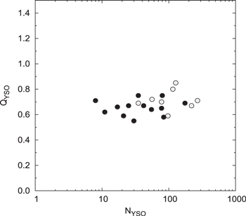
Figure 21. Structural Q parameter (QYSO) for the YSOs in the cores (filled circles) and in the active regions (open circle).
Download figure:
Standard image High-resolution imageWe compared the Q parameters for Class I and Class II sources (see Table 6), and found that the Class I sources are distributed more hierarchically than the Class II sources (QClass I < QClass II). A similar result is shown by Chavarría et al. (2014) and Schmeja et al. (2008) for low-mass SFRs and is likely a consequence of the cluster's dynamic relaxation.
4.2.5. Associated Molecular Material
The mean AK values for the identified cores have been found to be between 0.5 and 1.6 mag, with a median value of 1.1 mag (cf. Table 6 and Figure 22). This is very similar to the values given by Chavarría et al. (2014) for LECs. However, the peak value of AK (2.3 mag) for the current sample is higher than the value (1.5 mag) reported for LECs by Chavarría et al. (2014). We found a weak correlation between the peak AK and the number of cluster members (cf. Figure 22). The median AK value for the whole active region is 0.8 mag, which is lower than the core value, naturally indicating the distribution of higher density YSOs toward the high-density molecular clouds.
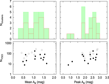
Figure 22. Histogram showing the mean K-band extinction (upper-left panel) and the plot of the mean K-band extinction vs. the number of cluster members (lower -left panel). The red solid histogram and filled circles are for the cores, and the green dotted histogram and open circles are for active regions. (Right panels): same as left, but for the peak K-band extinction distribution.
Download figure:
Standard image High-resolution image4.2.6. Jeans Length
Gutermuth et al. (2009) analyzed the YSO spacings of the YSOs in the stellar cores of 36 star-forming clusters and suggested that Jeans fragmentation is a starting point for understanding the primordial structure in SFRs. We also calculated the minimum radius required for the gravitational collapse of a homogeneous isothermal sphere (Jeans length "λJ") in order to investigate the fragmentation scale by using the formulae given in Chavarría et al. (2014).
The Jeans length λJ for the cores in the current study has values between 0.2 and 1 pc, with a median value of 0.46 pc (cf. Tables 5 and 6). We also compared λJ and the mean separation "SYSO" between the cluster members (Figure 23), and found that the ratio λJ/SYSO has an average value of 4.9 ± 1.2. Similarly, Chavarría et al. (2014) reported the ratio for their sample of embedded clusters as 4.3 ± 1.5. The present results agree with a non-thermal driven fragmentation because it took place at scales smaller than the Jeans length (Chavarría et al. 2014).
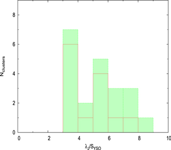
Figure 23. Histogram showing the distribution of the ratio between the cluster Jeans length (λJ) and the mean projected distance between the members of cores and active regions. The red solid histogram is for the cores, and the green dotted histogram is for active regions.
Download figure:
Standard image High-resolution image4.2.7. Molecular Content
We calculated the molecular mass of the identified cores and active regions using the extinction maps generated in the Section 3.3. First, we converted the average AV value (corrected for foreground extinction) in each grid of our map into H2 column density using the relation given by Dickman (1978) and Cardelli et al. (1989) (i.e., N(H2) = 1.25 × 10²¹ × AV cm−2 mag−1). Then, this H2 column density was integrated over the convex hull of each region and multiplied by the H2 molecule mass to get the molecular mass of the cloud. The extinction maps used for this are shown in Figures 10–17. The extinction law, AK/AV = 0.090 (Cohen et al. 1981) was used to convert the AK values of our maps to AV. Foreground contributions were corrected using the relation:  = 0.15 × D (Indebetouw et al. 2005; D is distance in kpc). The properties of the molecular clouds associated with the cores and active regions are listed in Table 5. The cores in the present sample show a wide range in their cloud-mass distribution (∼20 to 2400 M⊙), with a median value around 130 M⊙.
Lada et al. (2010) found that the number of YSOs in a cluster is directly proportional to the dense cloud mass M0.8 (the mass above a column density equivalent to AK ∼ 0.8 mag) with a slope equal to one. This gives an empirical relation between the content of YSOs and their parent molecular cloud. Recently, Chavarría et al. (2014) checked the same relation for their sample of embedded clusters and found a similar slope of 0.89 ± 0.15 between the mass of the dense cloud and the number of cluster members. This suggests that the star-formation rates depend linearly on the mass of the dense cloud (Lada et al. 2010). We also calculated the M0.8 (cf. Table 5, as explained in Chavarría et al. 2014) for our sample of BRCs. We find that the number of YSOs is proportional to M0.8, with a slope of 0.47 (cf. Figure 24); this is very similar to the slope of 0.5 calculated by Chavarría et al. (2014) when they did not correct their sample for the nondetection of fainter members. Once they applied the corrections for these nondetections, they found an almost similar slope (0.89 ± 0.15) as that given by Lada et al. (2010). The data used and the distances of the present sample of BRCs (1–2.7 kpc) are more or less similar to the embedded clusters (1.6–2.7 kpc) studied in Chavarría et al. (2014). We therefore expect a similar level of nondetection for our sample. Hence, it may give a similar relation as that of Lada et al. (2010). In summary, we can at least say that there is a linear relation between the dense cloud mass and the number of YSOs for the present sample of BRCs.
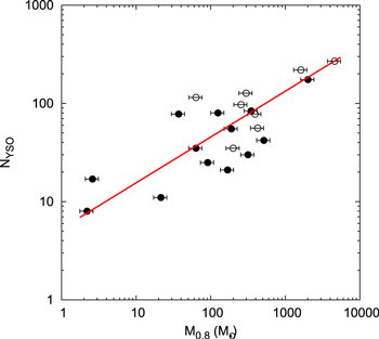
Figure 24. Relation between the number of YSOs "NYSO" and the molecular mass above AK = 0.8 mag (M0.8) in the cores (filled circles) and active regions (open circles). The solid line shows the best fit to the data points.
Download figure:
Standard image High-resolution image4.2.8. Star Formation Efficiency (SFE)
The wide range in the observed YSO surface densities provides an opportunity to study how this quantity is related to the observed SFE and the properties of the associated molecular cloud (Gutermuth et al. 2011). Recent works indicate that SFE increases with the stellar density. Evans et al. (2009) showed that YSO clusterings of the higher surface density tend to exhibit higher SFE (30%) than their lower density surroundings (3%–6%). Koenig et al. (2008) found SFEs of >10%–17% for high surface density clusterings and 3% for lower density regions.
We calculated the SFE, defined as the percentage of gas mass converted into stars by using the cloud mass derived from AK inside the cluster convex hull area and the number of YSOs found in the same area (see also Koenig et al. 2008). For simplicity, we assigned a 0.5 solar mass (cf. Koenig et al. 2008) to each of the identified YSOs and found SFEs between 3% and 30% with an average of ∼14%. Chavarría et al. (2014) obtained the SFE of a range of 3%–45% with an average 20% for the sample of embedded clusters. Our results are comparable to those of Chavarría et al. (2008) for the S254 region (4%–33% range and 10% average), with the exception of G192.54-0.15. Although the cluster G192.54-0.15 is located inside the H ii region "Sh2-254" (it has a distance of 2.4 kpc), the authors concluded that it is located in the background of the complex at a distance 9 kpc, based on its kinematics using the rotational model from Brand & Blitz (1993). The SFE of G192.54-0.15 is 54% for the distance of 2.4 kpc, then decreases to 1% if we adopt 9 kpc.
The present SFE values are in agreement with the efficiencies needed to go from the core mass function to the initial mass function (e.g., 30% in the Pipe nebula and 40% in Aquila, from Alves et al. 2007; André et al. 2010, respectively). The SFE distribution as a function of the number of the cluster member of each region is shown in Figure 25. There seems to be no correlation between them. This suggests that the feedback processes may start having an impact only in the later stages of the cluster evolution.

Figure 25. Star formation efficiency in the cores (filled circles) and in the active regions (open circles) with respect to the number of YSOs "NYSO."
Download figure:
Standard image High-resolution image
4.3. Biases
4.3.1. Effect of Uncertainty in Distance on the Analyses
Because the distances of the BRCs studied in the present survey have been taken from the literature (cf. Section 1), and are essentially the photometric distances of the bright ionizing source(s) with typical uncertainties of the order of ∼10%, this will have corresponding effects on the various parameters given in Tables 5 and 6. For example, as for Rhull, Rcirc, ρ, MST/NN2 length, and Dcrit., the dependence on the distance is simple and linear, therefore the percentage error associated with them due to the error in distance would be of the same order. The uncertainty due to it would be largest in the derived mass, stellar density, and SFE (∼20%), whereas the Jeans length would be in error by 15%. We also plotted these errors in the Figures 19, 20, 24, and 25. There are no significant changes in the distributions in the figures.
4.3.2. Effect of Non-detection of YSOs on the Analyses
The detection of YSOs is affected by the presence of bright infrared sources, bright nebulosity, and high crowding in the BRCs; we expect varying degrees of the detection completeness as a function of these factors. To quantitatively analyze these effects, we followed the same approach as demonstrated by Chavarría et al. (2014). Percentage of the corrected number of cluster members ( ) can be estimated from the equation given by Chavarría et al. (2014), i.e.,
where IR is the percentage of cluster members without IR excess and k is the percentage of synthetic stars with K magnitudes fainter than the 90% completeness limit of a synthetic cluster with similar properties as the observed clusters. Chavarría et al. (2014) found that k varies on average by 10% for their sample of embedded clusters. The percentage of cluster members without IR excess in the present sample of BRC should be of the order of 10% (cf. Section 3.1). Therefore, the percentage of lost YSOs will be around 20% of the total YSOs identified in the present survey in each BRC. This bias will have a considerable effect on the reported peak YSO surface densities, as well as on the higher density portions of the NN surface density maps. We expect only a modest effect on the mean YSO surface densities and overall member counts. As the completeness decreases, we expect to lose preferentially those stars that are deeply embedded in the nebulosity of the BRCs, and most of them are likely of a younger evolutionary class (Class I) located in the cores. Therefore, most probably, adding non-detected stars might complement some of the results in this study.
5. CONCLUSION
We carried out deep- and wide-field NIR observations of eight southern BRCs previously categorized as triggered candidates by Urquhart et al. (2009) using the ISPI camera on the 4 m CTIO Blanco telescope. These data along with the Spitzer archive data have been used to identify deeply embedded low-mass YSOs. Spatial distribution of these YSOs was compared with their associated molecular clouds, which were inferred by the extinction analysis. Quantitative techniques were used for analyzing the spatial structure of the YSO aggregates. The main results of our studies are as follows:
- 1.We identified a large number of YSOs, implying recent star formation in each of these BRCs. The number of the YSOs ranges from 44 to 433. This sample of YSOs is complete down to subsolar masses. We classified these YSOs based on their excess emission in IR.
- 2.Isodensity contours of the YSOs and NIR extinction maps for the regions studied were generated and compared with those of other SFRs. The YSOs are generally distributed in groups in the regions of higher extinction, peaking at or near the peak of the molecular column density. A majority of the younger population (i.e., Class I sources) belong to these groups, whereas the comparatively older population (i.e., Class II objects) is more randomly distributed throughout the regions. This distribution is in accordance with the notion that star formation usually takes place inside the dense cores of the molecular clouds and the YSOs often follow their clumpy structures.
- 3.19%–46% of the YSOs in the present sample of BRCs are a scattered population. Out of these, 62% are comparatively older Class II objects (cf. 38% in the cores). This higher percent in the outer regions can be attributed to their dynamical evolution.
- 4.The concentrations of YSOs in our sample have similar projected NN spacings as in many other embedded cluster cores, having a well-defined single peak that indicates a significant degree of Jeans fragmentation. NN2, being more sensitive to the local density fluctuations, shows a median value of 0.03 pc for the peak of its histogram; whereas NN6, which is an indicator of larger scale fluctuation, shows a comparatively larger peak value (0.19 pc).
- 5.The Class I sources are associated with higher extinction and are located relatively closer to one another than the Class II sources. Higher numbers of younger sources in the inner regions of BRCs with high column densities of the molecular cloud confirm that the young protostars are usually found in regions with marginally higher surface densities than the more evolved PMS stars.
- 6.MST analyses is used to isolate star-forming stellar cores from a diffuse, sparsely distributed, and potentially varying density background. We extracted 13 stellar cores of eight or more members. The active regions in all studied BRCs contain in total 997 YSOs, out of which 602 (60%) belong to the cores. The median MST branch length in these cores is found to be 0.09 pc. The members of these cores are mostly younger YSOs.
- 7.Several basic structural measurements of these cores have been done, finding that the median core is 0.6 pc in radii and somewhat elongated (aspect ratio of 1.45), of relatively low density (60 pc2), small (35 members), young (66% Class I), and partially embedded (median AK = 1.1 mag).
- 8.BRCs show fractal distribution of YSOs in their inner regions. Also, the Class I sources are distributed more hierarchically than the Class II, which is likely a consequence of the dynamical relaxation. The Jeans lengths for the cores have values between 0.2 and 1 pc, with a median value of 0.46 pc. Longer Jeans lengths in comparison to YSO separations support the non-thermally driven fragmentation in the BRCs.
- 9.The cores in the present sample show a wide range in their mass distribution (∼20–2400 M⊙) with a median value around 130 M⊙. We found a linear relation between the density of the clouds and the number of YSOs for the present sample of BRCs. We also found that the SFEs for the identified cores were between 3% and 30%, with an average of ∼14%. These values are in support of the previous findings, which agree with the efficiencies needed to go from the core mass function to the initial stellar mass function.
The observations reported in this paper were carried out using the BLANCO telescope at CTIO. We thank the staff members for their assistance during the observations. Financial support for JB and RK was provided by the Ministry of Economy, Development, and Tourism's Millennium Science Initiative through grant IC120009, awarded to The Millennium Institute of Astrophysics, MAS. and Fondecyt Reg. No. 1130140 and 1120601. This work is based in part on data obtained by the Spitzer Space Telescope, which is operated by the Jet Propulsion Laboratory, Caltech, under a contract with NASA. Support for this work was provided by NASA through a contract issued by JPL/Caltech. This publication also makes use of data from the Two Micron All Sky Survey, which is a joint project of the University of Massachusetts and the Infrared Processing and Analysis Center/California Institute of Technology, funded by the National Aeronautics and Space Administration and the National Science Foundation.
Footnotes
- 9
IRAF is distributed by the National Optical Astronomy Observatory, which is operated by the Association of Universities for Research in Astronomy (AURA) under a cooperative agreement with the National Science Foundation.
- 10
- 11