
Abstract
In the dry etching process using fluorocarbon (FC) gas, deposited amorphous-CFx (a-CFx) films in patterns, such as holes and trenches, strongly affect the etching performance. The influence of the FC gas molecular structures and their atomic compositions on the formation of a-CFx films at different positions in the holes were investigated. It was found that the deposition region and thickness of the a-CFx film strongly depend on the molecular structures of the FC gas, such as double bonds, benzene rings, and the atomic ratio of fluorine to carbon.
Export citation and abstract BibTeX RIS
In the era of big data, storage devices with a high bit density are required to store more information in a limited volume. To meet these demands, the feature sizes of semiconductor memory, such as 2D-NAND flash, have been miniaturized. However, the downscaling of 2D-NAND has been limited by cell degradation resulting from several factors including signal interference between adjacent cells and data retention. 1) To overcome this problem, 3D flash memory, in which memory cells are stacked three-dimensionally, has been developed. 2) Nonetheless, a major challenge in manufacturing 3D flash memory is related to the fabrication of high-aspect-ratio (AR) memory holes through a large number of stacked films constructed by SiO2/polycrystalline Si pairs is required by a dry etching process. 3) Therefore, the key technology in 3D flash memory manufacturing is a high-AR hole-etching process. Usually, selective etching of SiO2 with a carbon mask is achieved by reactive ion etching (RIE) using fluorocarbon (FC) gases. The corresponding mechanism of the surface reaction has been previously studied. 4,5) In addition, to improve the selectivity and etch rate, research on etching using various FC gases with different compositions and structures such as CF4, C2F6, C2F4, C3F6, C4F6, C4F8, C5F8, and C6F6 has been conducted. 6–11) In the RIE process with FC gas, a suitable thickness of amorphous-CFx (a-CFx ) film deposited on the mask or sidewalls of the hole by CFx radicals plays an important role in protecting the structures from ion bombardment, leading to high selectivity and reduction of side etching. Nevertheless, it has been reported that excessive or lack of a-CFx film deposition leads to various hole profile issues, such as bowing (increased hole diameter near the middle of a hole 12–14)), distortion, 15,16) and striation (vertical scratches on the sidewall 17)). Furthermore, the conductivity of a-CFx films has also been reported, where associated features may induce charging at the bottoms of the high-AR holes during the RIE process. 18–21) This charge-up phenomenon is reported to infer the twisting of holes. 22) These reports suggest that controlling the thickness of the a-CFx film and the AR region where the a-CFx film is deposited can overcome the various hole shape problems, which occur during the high-aspect-ratio-contact (HARC) process. To control the thickness of the a-CFx film in the hole, it is necessary to examine the kinetics of various CFx radicals and control the a-CFx film thickness for each AR. Izawa et al. reported that a-CFx films could be formed deeper into the hole by increasing the surface temperature of the sample. 12) Similar reports have investigated the relationship between the sample surface temperature and the sticking coefficient of CFx radical. 23,24) In addition, it has been reported that the thickness of the a-CFx film increases with the amount of CF2 radical. 25,26) Takahashi et al. showed that C5F8 gas, which generates more CF2 radicals compared to C3F6 and C4F8, is more easily polymerized on silicon wafers. 27) However, there are few reports on the relationship between FC gas molecular characteristics (structure and composition ratio) and a-CFx film thickness relative to each AR. In this study, we investigated the characteristics of the a-CFx film relative to AR, which was formed by several FC gases having different bonds, such as single bonds, double bonds, or benzene rings. We further discussed the effects of the FC gas structure and composition ratio on a-CFx film formation.
Figure 1 shows a schematic of our experimental setup. Plasma was formed in a dual-frequency (3.2/100 MHz) capacitively coupled plasma (CCP) reactor, as shown in Fig. 1 (a). The input power of the high frequency was set to 300 W, whereas that of the low frequency was set to 0 W to prevent overheating of the sample due to ion bombardment. The temperatures of the upper electrode, sidewall, and bottom electrode were maintained at 100 °C, 80 °C, and 20 °C, respectively. The FC gases used in this study were hexafluoro-1,3-butadiene (C4F6), octafluorocyclobutane (C4F8), hexafluorobenzene (C6F6), tetrafluoroethylene (C2F4) and tetradecafluoromethylcyclohexane (C7F14). A gas mixture of FC (flow rate: 39 sccm) and Ar (flow rate: 94 sccm) was injected into the reactor from the upper electrode through a showerhead. The gas pressure was maintained at approximately 2 Pa. The molecular structure of FC is shown in Fig. 1 (b). C4F8 and C7F14 are cyclic, C2F4 contains a double bond, C4F6 has two double bonds, and C6F6 contains a benzene ring. The atomic composition ratios of fluorine to carbon (F/C) of C4F8, C7F14, and C2F4 were 2, and the F/C ratios of C4F6 and C6F6 were 1.5 and 1, respectively. Aluminum nitride (AlN) plates with rectangular grooves (0.4 × 5 × 50 mm3) were placed on the Si substrate, as shown in Fig. 1(c). Following plasma exposure, the Si surface was analyzed by X-ray photoelectron spectroscopy (XPS). The samples were exposed to a mixed gas plasma consisting of FC gas and Ar for 1 min. Under our experimental process conditions, the temperature of the substrate was confirmed to be below 40 °C. A gap was made between the AlN plate and Si substrate. The migration behavior of the CFx radicals generated in the plasma can be investigated by measuring the thickness of the formed a-CFx film in the lateral direction. This is mainly because the AlN plate blocks the ions above this gap region, as shown in Fig. 1(d). As shown in Fig. 1(e), the a-CFx film thickness was measured using either scanning electron microscopy (SEM) or XPS. The film thickness was calculated from XPS measurements using Eq. (1): 28,29)
where d is the a-CFx thickness, λ is the mean free path of the photoelectrons in the a-CFx film (approximately 2.5 nm), and ϕ is the photoelectron emission angle (45°). I0 and I are the Si 2p spectral intensities of the Si substrates before and after the plasma treatment, respectively. In addition, the degree of dissociation by the electron impact with an energy of 70 eV for FC gases was measured by a quadrupole mass spectrometer (QMS) to reveal the influence of the structure and composition of the FC gas molecule on the a-CFx film deposition.

Fig. 1. (Color online) Schematic of our experimental system of (a) the reactor, (b) FC gases, (c) sample to evaluate the CFx radical migration, (d) schematic of a-CFx film deposition, and (e) measurement point for SEM or XPS analysis.
Download figure:
Standard image High-resolution imageFigure 2 shows the AR dependencies of the a-CFx film thickness deposited by various FC gas plasmas in the (a) low-AR region up to 5 and (b) higher AR region up to 40. The thickness of the a-CFx film formed in the low-AR region increased in the following order: C6F6, C4F6, C7F14, C2F4, and C4F8. The a-CFx films formed by C4F6 or C6F6 plasma were noticeably thicker than those formed by the other gases. Nonetheless, there was no significant difference in the thicknesses of the a-CFx films deposited with C2F4, C4F8, and C7F14 gases. On the other hand, in the high-AR region, the a-CFx films deposited with C2F4, C4F8, and C7F14 plasmas were thicker than those with C4F6 and C6F6 plasmas, as shown in Fig. 2(b). From the results observed above, in the low-AR region, thick a-CFx films are deposited by plasma exposure to a gas with multiple double bonds (C=C) or benzene rings and a small F/C ratio, such as C4F6 and C6F6. Conversely, in the high-AR region, relatively thick a-CFx films were deposited by plasma exposure to a gas with fewer unsaturated bonds in the FC gas molecules and a high F/C ratio, such as C2F4, C4F8, and C7F14.
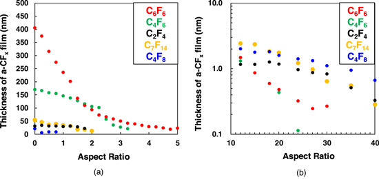
Fig. 2. (Color online) AR dependence of the a-CFx film thickness formed by various FC gas plasmas. The AR is (a) up to 5 and (b) 10 to 40.
Download figure:
Standard image High-resolution imageFigure 3 shows the fragmentation of the FC gases after an electron impact of 70 eV, as detected by QMS. The major fragment species are shown in Table I. FC gases with double bonds or benzene rings, such as C2F4, C4F6, and C6F6, are hardly decomposed. The larger the number of π bonds in the double bond or benzene ring structure, the less decomposition is observed. Conversely, in the case of gases without double bonds, such as C4F8 and C7F14, no parent ion species are detected. These results suggest that the double bonds included in the molecule help maintain their structures against electron attack. The F/C ratio of the majority of fragments is strongly influenced by the F/C ratio of the parent gas. For example, C-rich fragments like C6F6 + and C5F3 + are mainly observed in the case of using C-rich C6F6 gas. In contrast, F-rich fragments, such as C3F5 +, are mainly detected using F-rich C4F8 and C7F14 gases.
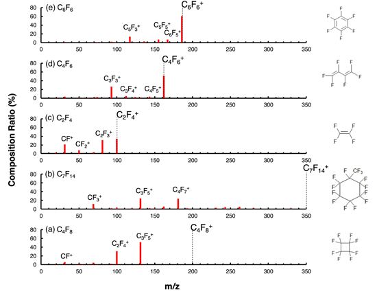
Fig. 3. (Color online) Composition ratio of the observed positive ion species generated by the electron impact whose energy is 70 eV for FC gases of (a) C4F8, (b) C7F14, (c) C2F4, (d) C4F6, and (e) C6F6.
Download figure:
Standard image High-resolution imageTable I. List of the observed major positive ion species generated by the electron impact whose energy is 70 eV for C4F8, C7F14, C2F4, C4F6, and C6F6 gas.
| C4F8 | C7F14 | C2F4 | C4F6 | C6F6 | ||||||||||
|---|---|---|---|---|---|---|---|---|---|---|---|---|---|---|
| m/z | Flaqment | Ratio(%) | m/z | Flaqment | Ratio(%) | m/z | Flaqment | Ratio(%) | m/z | Flagment | Ratio(%) | m/z | Flaqment | Ratio(%) |
| 131 | C3F5 + | 51.3 | 131 | C3F5 + | 24.5 | 100 | C2F4 + | 34.2 | 162 | C4F6+ | 51.6 | 186 | C6F6 + | 60.9 |
| 100 | C2F4 + | 30.9 | 181 | C4F7 + | 23.6 | 81 | C2F3 + | 31.4 | 93 | C3F3 + | 26.5 | 117 | C5F3 + | 13.7 |
| 31 | CF+ | 5.6 | 69 | CF3 + | 11.4 | 31 | CF+ | 21.2 | 112 | C3F4 + | 4.6 | 167 | C6F5 + | 7.1 |
| 69 | CF3 + | 4.5 | 162 | C4F6 + | 5.9 | 50 | CF2 + | 7.6 | 143 | C4F5 + | 3.5 | 155 | C5F5 + | 7.0 |
| 93 | C3F3 + | 2.3 | 262 | C6Fl0 + | 5.1 | 69 | CF3 + | 2.2 | 31 | CF+ | 3.1 | 136 | C5F4 + | 2.6 |
| 50 | CF2 + | 19 | 243 | C6F9 + | 4.4 | 19 | F+ | 2.1 | 74 | C3F2 + | 2.7 | 93 | C3F3 + | 2.4 |
| 62 | C2F2 + | 1.0 | 100 | C2F4 + | 3.1 | 124 | C4F4 + | 2.6 | 31 | CF+ | 1.4 | |||
| 231 | C5F9 + | 2.8 | 69 | CF3 + | 1.2 | |||||||||
| 281 | C6F11 + | 2.6 | 131 | C3F5 + | 1.0 | |||||||||
| 193 | C5F7 + | 2.6 | ||||||||||||
| 143 | C4F5 + | 2.3 | ||||||||||||
| 93 | C3F3 + | 2.0 | ||||||||||||
| 331 | C7F13 + | 1.9 | ||||||||||||
| 119 | C2F5 + | 1.6 | ||||||||||||
| 150 | C3F6 + | 1.3 | ||||||||||||
Next, the chemical bonding states of the a-CFx film were analyzed using XPS to understand the AR dependence of the a-CFx film characteristics. Figures 4(a)–4(e) show the C 1 s spectra of the deposited a-CFx films at AR = 0, 9, 20, 30, and 40. As shown in Figs. 4(a)–4(e), a thick a-CFx film with four peaks corresponding to C–CFx , C–F, C–F2, and C–F3 bonds was observed in the low-AR region. The attribution for each peak was confirmed in previous reports. 30,31) As the AR increased and the a-CFx film became thinner, signals originating from the contamination peak under the a-CFx film were observed. Figure 4(f) shows a comparison of the areal ratios of C–CFx , C–F, C–F2, and C–F3 in the C1s spectra at AR = 0. The composition of the a-CFx films was strongly influenced by the F/C ratio of the parent gas. The a-CFx films deposited by F-rich C4F8, C7F14, and C2F4 gases have more F-rich components, such as C–F2 and C–F3. As the composition of the parent gas becomes C-rich, such as C4F6 and C6F6, C-rich C–CFx and C–F components increase. A very small C–F3 peak was observed in the a-CFx film formed by C6F6 even at AR = 0. This is explained by the fact that the C6F6 gas is composed solely of CF groups, where it is difficult to form a CF3 group with two F atoms bonded to the CF group. This suggests that the composition ratio of CFx radicals produced in the plasma is greatly influenced by the composition ratio of the parent FC gas. For a-CFx films deposited by F-rich gases such as C4F8, C7F14, or C2F4, as AR increases from 0 to 30, the peak intensities originating from the C–CFx and C–F bonds decrease significantly, whereas the peak intensities of the C–F2 and C–F3 bonds decrease slightly, as shown in Figs. 4(a)–4(c). Therefore, the atomic composition ratio of the a-CFx films deposited in the high-AR region gradually became F-rich. This suggests that only F-rich radicals with high C–F2 and C–F3 contents can reach the high-AR region. This can be attributed to the difference in the sticking coefficients between the C-rich CFx radicals and F-rich CFx radicals. The sticking coefficient of F-rich CFx radicals such as CF2 is reported to be lower than that of C-rich radicals; 12) hence, F-rich CFx radicals can reach high-AR regions. On the other hand, no C–F2 and C–F3 peaks were observed in the a-CFx film deposited by C4F6 or C6F6 plasmas in the high-AR regions (e.g., AR = 30), as shown in Figs. 4(d) and 4(e). This may be because F-rich gases such as C4F8, C7F14, and C2F4, F-rich fragments with high C–F2 and C–F3 contents are unlikely to be generated in the plasma. C4F6 and C6F6 gases are not easily decomposed, and few F-rich fragments are generated compared to C4F8, C7F14, and C2F4, as shown in Table I. For example, in the case of C4F6 gas, the amount of F-rich fragments (e.g., F/C > 1.5), such as CF3 + and C3F5 +, is approximately 2%. In C6F6 gas, no F-rich fragments were measured. Although the C4F6 molecule has two CF2 groups, the gas is not easily decomposed because of its double bond, and the amount of CF2 radicals produced in the plasma is thought to be low, as shown in Fig. 3 (d).
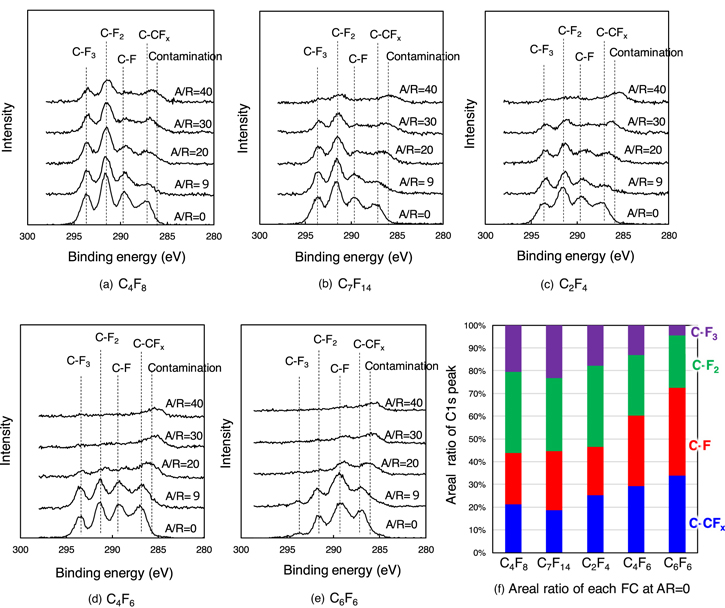
Fig. 4. (Color online) C 1 s spectra of the deposited a-CFx film at AR = 0, 9, 20, 30, and 40 after plasma exposure of (a) C4F8, (b) C7F14, (c) C2F4, (d) C4F6, and (e) C6F6 and (f) comparison of the areal ratio of C1s peak at AR = 0.
Download figure:
Standard image High-resolution imageFigure 5 shows a schematic model of the relationship between the atomic composition ratio (F/C) and the structure of the FC gases on a-CFx deposition. In the C–F bond, it is estimated that electrons are attracted near the F atom because of their higher electron affinity compared to that of the C atom. Therefore, F is relatively electron-rich, whereas C is relatively electron poor. F-rich CFx radicals are less reactive to nucleophilic attack, 32) leading to a low sticking coefficient because most molecules are covered with electron-rich F, and the unpaired electron on C is strongly hindered. When there are many F-rich radicals in the plasma, after the CFx radicals are attached to the substrate, the newly approaching CFx radicals cannot approach the same location because of electrostatic repulsion, as shown in Fig. 5(a). Therefore, a thin CFx film was deposited in the high-AR region. In comparison, the unpaired electron on C of the C-rich CFx radicals was less hindered, leading to a high sticking coefficient and reactivity to another unpaired electron on the substrate. After the C-rich radical attaches to the substrate, the newly approaching CFx radicals easily approach and react in the same place due to the absence of electrostatic repulsion, as in the case of F-rich radicals, as shown in Fig. 5(a). Therefore, the a-CFx film is thickly deposited in the low-AR region and not so much in the high-AR region because most of the C-rich CFx radicals are consumed in the low-AR region. As mentioned above, the F-rich CFx radicals generated in C4F8, C7F14, and C2F4 plasmas reach the higher AR region and form a-CFx films, as shown in Fig. 5(b). In contrast, when gases with F/C ratios lower than 2, such as C4F6 and C6F6, are used, many C-rich CFx radicals with high sticking coefficients are generated in the plasma, and thick a-CFx films are deposited in the low-AR region. It follows that the C-rich CFx radicals did not reach the higher AR region and a thin a-CFx film was thus observed. FC gases with two double bonds, such as C4F6, generate radicals with two unpaired electrons and one double bond, which promotes further polymerization compared to FC gases with one double bond. 33) Therefore, a-CFx films deposited in the low-AR region by C4F6 plasma exposure are considerably thicker than those deposited by C4F8, C7F14, and C2F4 plasma exposures. C2F4 gas has one double bond, but its high F/C ratio prevents the formation of thick a-CFx films because of the large electrostatic repulsion between the F-rich CFx radicals. In addition, a single double bond in the structure cannot promote further polymerization. The a-CFx film deposited using the C6F6 plasma was significantly thicker than that deposited using the C4F6 plasma. This could be attributed to the molecular structure of C6F6. Molecules with benzene rings stack face-to-face owing to their π-π interaction. 34) This interaction causes radicals with benzene ring structures to cluster in the low-AR region, which may result in significantly thicker a-CFx film formation in regions where AR is approximately 0. As described above, the AR dependence of a-CFx film deposition is affected by two factors: (1) magnitude of electrostatic repulsion derived from the F/C ratio of the CFx radicals, and (2) multiple double bonds or benzene rings in the FC gas molecules. To form a-CFx films in high-AR regions, it is important to increase the F/C ratio of the FC gas and generate F-rich CFx radicals in the plasma. Conversely, by lowering the F/C ratio, including multiple double bonds or benzene rings in the FC gas, and generating C-rich CFx radicals in the plasma, a-CFx films can be deposited only in the low-AR region. To form thicker a-CFx films, it is effective to either use FC gases with two or more double bonds, which consequently lowers the F/C ratio and promotes polymerization, or FC gases with benzene rings to promote stacking via π-π interactions.

Fig. 5. (Color online) Model of the relationship of the composition ratio (F/C) and structure of FC gases on a-CFx film deposition. (a) Schematic illustration of the reactivity of CFx radicals, (b) a-CFx film deposition by F-rich CFx radical, (c) a-CFx film deposition by C-rich CFx radicals with multiple double bonds, and (d) a-CFx film deposition by C-rich radicals with a benzene ring.
Download figure:
Standard image High-resolution image
In summary, the effects of the composition ratio and structure of the FC gas on the deposition of a-CFx films were investigated in a high-aspect-hole structure. When the F/C ratio of the FC gas was 2 or higher, F-rich CFx radicals with low sticking coefficients were easily generated in the plasma, and a-CFx films were deposited up to the high-AR region. However, as the F/C ratio decreased, C-rich CFx radicals with high sticking coefficients were formed in the low-AR region, whereas thin a-CFx films were deposited in the high-AR region. The multiple double bonds in the FC gas molecules promote polymerization, resulting in a thicker a-CFx film that can be deposited in the low-AR region. Furthermore, FC gas with a benzene ring structure creates a thicker a-CFx film in the region where AR is approximately 0, which may be attributed to the molecular assembly owing to the π-π interaction of benzene rings. These process controls of a-CFx film formation inside the patterns can lead to high etching performance.