
Abstract
Optical correlation-domain reflectometry (OCDR), which is known as one of the fiber-optic techniques for distributed reflectivity sensing, conventionally included an acousto-optic modulator, a reference path, and erbium-doped fiber amplifiers in its setup. In this work, by removing all of these components simultaneously, we develop a super-simplified configuration of OCDR, which consists of a light source and a photodetector only. We experimentally show that this system can still perform distributed reflectivity sensing with a moderate signal-to-noise ratio, which will boost the portability and cost efficiency of the OCDR technology.
Export citation and abstract BibTeX RIS
Recently, the health diagnosis of rapidly spreading optical fiber networks has been actively pursued. Fiber-optic reflectometry is known as a technique to measure distributed reflective points along a fiber under test (FUT) for detecting bad connections or splices. 1–8) Several configurations have been developed so far, including optical time-domain reflectometry 1,9–12) and optical frequency-domain reflectometry, 2,13–17) which have the advantages of a wide measurement range and high spatial resolution, respectively. However, it is difficult for these configurations to perform high-speed sensing at an arbitrary position (or positions) along an FUT; i.e. they do not have a nature called "random accessibility." 18)
Random accessibility has been achieved by another configuration termed as optical correlation-domain reflectometry (OCDR), which operates on the basis of synthesized optical coherence functions (SOCF). 18–30) SOCF-OCDR has relatively high spatial resolution, and again, it can selectively measure arbitrary points or areas in an FUT at high speed. Its recent applications include light detection and ranging (LiDAR). 31)
In a conventional SOCF-OCDR system, three kinds of optical devices/components are often used: (i) erbium-doped fiber amplifiers (EDFAs) for increasing the incident and reflected optical powers, (ii) an acousto-optic modulator (AOM) for optical heterodyne detection to mitigate the influence of low-frequency noise, and (iii) a reference optical path for controlling the measurement position. To date, the experimental setup of SOCF-OCDR has been simplified to reduce its size and cost by removing the AOM; 26) a trial to remove the reference path has also been performed. 28,29) In addition to the AOM and the reference path, if all the EDFAs can be removed from the setup, the system will be super-simplified.
In this work, we implement a super-simplified OCDR system without any use of the EDFAs, the AOM, or the reference path, and verify its basic operation via distributed reflectivity measurements. This system consists of only a light source and a photodetector (PD), which will be of great use for implementing cost-effective distributed reflectivity sensors.
SOCF-OCDR is based on optical correlation control; specifically, a sinusoidally frequency-modulated laser output is injected into the FUT. Then, a correlation peak, which serves as a measurement point, is generated in the FUT; 20) only the light reflected at the correlation peak is detected. By controlling the modulation frequency, the position of the correlation peak can be scanned along the FUT, and the distributed information on the reflected light along the FUT can be obtained. Strictly speaking, multiple correlation peaks are generated periodically (they have the orders; the zeroth correlation peak is defined as the peak that appears at the zero-optical-path-difference point of the incident and reference paths), and in a simple configuration, we leave only one peak in the FUT by limiting the length of the FUT. Therefore, the allowable FUT length D (i.e. the measurement range) is given by the interval of the neighboring correlation peaks as 20)

where c is the light velocity in a vacuum, n is the core refractive index, and fm is the modulation frequency of the laser output. The correlation peak has a certain width, which gives the spatial resolution Δz as 27)

where Δf is the modulation amplitude.
Subsequently, let us describe the principles of the simplified SOCF-OCDR configurations. In a standard system, through heterodyne detection, the beat signal appears around 0 Hz in the spectrum, where low-frequency noise is relatively high. To avoid this noise, by inserting a frequency shifter (such as an AOM) in the reference path, the beat signal is converted to higher frequency around tens of megahertz. However, we found that, even without the frequency shifter, the measurement can be properly performed by using the foot (e.g. several megahertz; with less effect of the low-frequency noise) of the beat spectral peak at 0 Hz. To further simplify the AOM-free configuration, we developed a reference-path-free SOCF-OCDR configuration (Fig. 1), in which the light Fresnel-reflected at the open end of the FUT is used as the reference light. 28) This open end is the zero-optical-path-difference point, where the zeroth correlation peak is constantly located. By increasing the modulation frequency, when the first-order correlation peak moves from the proximal end to the midpoint of the FUT, the second-order correlation peak starts to enter the FUT from the proximal end. Considering that the number of the correlation peaks (except for the zeroth one) inside the FUT should be only one, the measurement range is limited to the proximal half of the FUT, not determined by Eq. (1). If the EDFAs in the incident and reflected light paths can be additionally removed, this system will be super-simplified, consisting of only a light source and a PD.
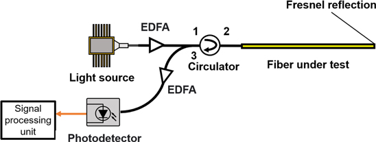
Fig. 1. (Color online) Schematic of the reference-path-free OCDR. EDFA: erbium-doped fiber amplifier.
Download figure:
Standard image High-resolution imageThe experimental setup of the super-simplified SOCF-OCDR is shown in Fig. 2. A laser diode (LD) at ∼1550 nm was employed. Sinusoidal frequency modulation was applied to the LD output by directly modulating the driving current of the LD. The modulation amplitude was 0.6 GHz, and the modulation frequency was swept from 6.462 to 11.997 MHz with a repetition rate of 100 Hz to scan the correlation peak. The LD output was injected into the sensing fiber via an optical circulator. The second-port fiber (∼1 m) of the circulator was connected to ∼1 m, ∼5 m, and ∼10 m long silica single-mode fibers (SMFs) using two angled-physical-contact (APC) connectors, one APC connector and one physical-contact (PC) connector, and one APC connector and one PC connector, respectively (see Fig. 2; note that the APC connectors and the PC connectors were intentionally coupled to induce high reflection). The end of the ∼10 m long SMF was an open-ended PC connector. We defined the FUT as the 16 m long region from the open end. The beat signal of the light reflected from the FUT and the light Fresnel-reflected at the open end was converted into an electrical signal using a PD. The PD output was guided to an electrical spectrum analyzer (ESA; video bandwidth: 300 MHz; resolution bandwidth: 30 kHz), and its spectrum from 0 to 5 MHz was observed. Using a zero-span function of the ESA, the temporal variation of the signal power at 2.5 MHz was output and monitored using an oscilloscope (OSC).
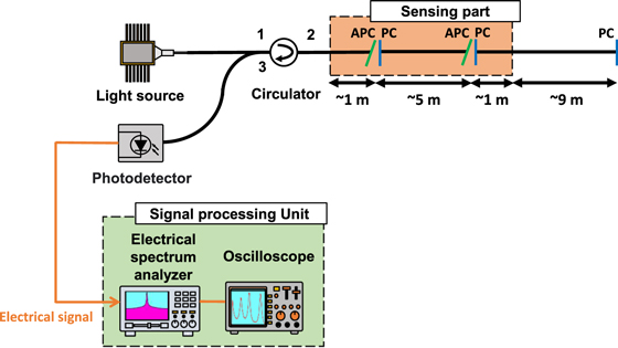
Fig. 2. (Color online) Experimental setup of the super-simplified OCDR. PC: physical-contact, APC: angled-physical-contact.
Download figure:
Standard image High-resolution imageWe measured the distributed reflectivity along the proximal half of the FUT when the incident optical powers were −9, 0, 9, and 14 dBm and evaluated the signal-to-noise ratios (SNRs). A variable-output LD was used when the incident optical powers were −9, 0, and 14 dBm, and a standard LD (CivilLaser) was used when the incident light power was 9 dBm.
Figures 3(a) and 3(b) are the experimental results, in which grayscale and red plots indicate the values obtained using the variable-output LD and the standard LD, respectively. Figure 3(a) shows the reflected power distributions measured along the proximal half of the FUT when the incident powers were −9, 0, 9, and 14 dBm. The vertical axis was normalized so that the maximum power at a 14 dBm incident power became 1. The horizontal axis indicates the distance from the FUT end. This super-simplified system successfully detected the high-reflection points at the correct positions. With increasing incident power, the peak power increased. Figure 3(b) shows the SNRs plotted as a function of the incident power. Here, we defined the SNR as the difference between the peak power at 15 m and the noise floor at 13 m. The SNR increased with increasing incident power, which shows that distributed reflectivity measurements can be performed with an SNR of at least 9 dB when the incident optical power is −9 dBm or higher. Note that this optical power is sufficiently lower than the output power of standard LDs.

Fig. 3. (Color online) (a) Normalized power distributions measured at different incident powers. (b) SNRs plotted as a function of the incident power.
Download figure:
Standard image High-resolution image
In conclusion, we implemented a super-simplified configuration of SOCF-OCDR consisting of only an LD and a PD by removing all of the AOM, the reference path, and the EDFAs. We experimentally showed that, using a standard moderate-power LD, this system can appropriately perform distributed reflectivity measurement along the proximal half of the FUT. As this system does not include any polarization-controlling devices, it is true that the measurement stability is somewhat lower, but we anticipate that our demonstration will be of great significance in developing cost-effective miniaturized systems not only for fiber-optic distributed reflectivity sensing but also for correlation-domain LiDAR 31) in the near future.
Acknowledgments
This work was supported by JSPS KAKENHI Grant Nos. 20J22160, 20K22417, and 21H04555, and the research grants from the Takahashi Industrial and Economic Research Foundation, the Yazaki Memorial Foundation for Science and Technology, and the Konica Minolta Science and Technology Foundation.