


Abstract
The ascent motion of an air bubble beneath an inclined plane is experimentally studied. The effects of the surrounding liquid viscosity and surface tension, the bubble radius and the tilt angle are investigated. A dynamical model is proposed. It opposes the buoyant driving force to the hydrodynamical pressure arising from the bubble motion and the capillary meniscus generated in front of the bubble in order to create a lubrication film between the bubble and the plate. This model is compared to experimental data and discussed.
Export citation and abstract BibTeX RIS
Introduction
The ascending motion of a bubble driven by buoyancy in a viscous fluid is, behind an apparent simplicity, a non-trivial problem, especially when the bubble interacts with a surface. This situation is of interest in both practical applications (emulsification, boiling, cavitation, electrolysis...) and fundamental studies. The difficulties arise from the different scales of the problem: lengths vary from the bubble diameter to the distance between the bubble and the plane. Depending on these scales, inertia and viscous effects are in turn involved, and, eventually, they can be simultaneously relevant. Our study particularly focuses on this aspect and we address all the cases from the fully viscous to the almost fully inertial passing by situations where both effects matter.
Several shapes for the solid surface have been studied in the literature: bubbles in tubes and 2D channels (inclined or not) [1–10], bubbles beneath horizontal cylinders [11,12] and of course bubbles "under" a plane. In this last configuration many situations have been considered: vertical planes, horizontal planes and inclined planes. The case of the vertical plane has been widely studied; in this situation the wall acts on the bubble drag coefficient and the bubble migrates towards the wall. One can cite, for example, the work of Magnaudet et al. [13–15] where the inertia is considered. In the case of a horizontal plane, bubbles bounce on the surface (see, for example, [16–19]).
The present article takes place in the context of a bubble sliding beneath an inclined plane. This subject has already been explored experimentally [16,20–25], numerically [26] and theoretically [27,28]. The question of the bubble terminal velocity has been solved in terms of scaling laws for small Reynolds number and low inclination angles [22]. This question has also received a lot of attention in the case of large bubbles (large in comparison to the capillary length) [20,23,24,27]. The case of bubbles sliding beneath a plane with a Reynolds number larger than one and for bubbles diameters of the order of the capillary length  (detailed further) remains only partially treated by Masliyah et al. and Tsao et al. [16,21], who respectively interpreted the bubble motion in terms of drag coefficient and answered only qualitatively the problem.
We propose here a study focusing on millimetric bubbles sliding beneath an inclined plate with a tilt angle ranging from  to 40°. Water and silicone oils of various viscosities (between 1.5 cS and 131 cS) are used as surrounding fluids and totally wet the solid. We reached Reynolds numbers Re (for the bubble radius) between 10−2 and 4 · 102. By this mean, we recover the results obtained for small Re (for instance in [22]) and we investigate the situation where inertia dominates. We also explored the situation where inertia and viscous effects are both implicated and comparable. In the next section, we qualitatively present the shape adopted by the bubble as it rises in the fluid. Dimensionless numbers are presented and discussed. Thereafter, the lubrication film entrapped between the bubble and the plate is addressed, in terms of "contact" area. Modeling this area allows us to propose a dynamical model for the bubble motion, accounting for all the experimental parameters. Eventually, the obtained results are discussed and conclusion is drawn.
Setup
The experimental setup consists of a transparent rectangular box (26 × 3 cm2 horizontal area) with a height of 10 cm filled with liquid. A polycarbonate plate is immersed in the pool with a relative tilt θ to the horizontal varied from 5° to 40°.
Bubbles of controlled size are generated at the bottom of the tank thanks to a needle connected to a seringue filled with air. The bubble volume and initial radius ![$(R_0\in[0.5;3]\ \text{mm})$](https://content.cld.iop.org/journals/0295-5075/115/4/44001/revision1/epl18069ieqn11.gif) are measured along the path from the needle to the bottom of the inclined plate, where bubbles are in free motion. Bubbles arrive at the bottom of the inclined plate and rise beneath it thanks to buoyancy. A video camera records images from the side of the tank at a frame rate of 100 fps. A typical image of a rising bubble is presented in fig. 1.
are measured along the path from the needle to the bottom of the inclined plate, where bubbles are in free motion. Bubbles arrive at the bottom of the inclined plate and rise beneath it thanks to buoyancy. A video camera records images from the side of the tank at a frame rate of 100 fps. A typical image of a rising bubble is presented in fig. 1.
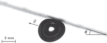
Fig. 1: Typical image of an air bubble  , immersed in a water bath, sliding under an inclined plate
  at a speed
  .
.
Download figure:
Standard imageTwo kinds of liquid have been used for the bath: distilled water and silicone oils of six different viscosities. In so doing, we can reach kinematic viscosity, ν, ranging between 1 cS and 131 cS and surface tension of 20 or 70 mN/m (see table 1 for full information).
Table 1:.
Kinematic viscosity ν, density ρ, surface tension γ and capillary length  of the different fluids used in the present study.
| Liquid |  |
 |
 |
 |
|---|---|---|---|---|
| Water | 1.0 · 10−6 | 1000 | 72 · 10−3 | 2.7 · 10−3 |
| Silicon oil 1.5 cS | 1.5 · 10−6 | 800 | 17.5 · 10−3 | 1.4 · 10−3 |
| Silicon oil 5 cS | 5 · 10−6 | 910 | 19.7 · 10−3 | 1.5 · 10−3 |
| Silicon oil 10 cS | 10 · 10−6 | 920 | 19.9 · 10−3 | 1.5 · 10−3 |
| Silicon oil 20 cS | 21 · 10−6 | 950 | 20.6 · 10−3 | 1.5 · 10−3 |
| Silicon oil 50 cS | 55 · 10−6 | 959 | 20.7 · 10−3 | 1.5 · 10−3 |
| Silicon oil 100 cS | 131 · 10−6 | 965 | 20.9 · 10−3 | 1.5 · 10−3 |
Phenomenology
Beneath the plate, the bubble rapidly reaches a stationary motion characterized by a constant velocity v and a rectilinear trajectory, emphasizing no net force acts on the bubble at that moment. This velocity value depends of course on the different parameters of the system: especially on the tilt angle θ and the kinematic viscosity ν. Exploring the velocity range, one can observe that the bubble experiences variable deformations as depicted in fig. 2.
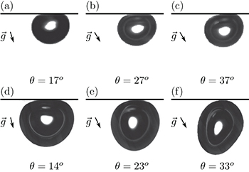
Fig. 2: Shape of an air bubble for three different tilt angle values. For (a)–(c) the radius is  and the surrounding fluid silicone oil 131 cS. We thus have
  . For (d)–(f) the radius is
  and the surrounding fluid water
  . Images are rotated such that the plate is horizontal (g vector indicates the vertical direction). Bubbles are going from right to left on the picture.
Download figure:
Standard imageThe shape for a bubble submitted only to surface tension is of course spherical. In the present situation, i.e., beneath an inclined plane, two forces are responsible for bubble deformations: the gravity force that flattens the bubble against the plane and the friction force that stretches the bubble perpendicularly to the plane.
We will then describe qualitatively the influence of each force on the bubble and try to describe the phenomenology encountered in our experiments. Considering the friction force leads us to introduce the Reynolds number Re, in order to determine the "nature" of the drag force: viscous or inertial. This Reynolds number reads as

where R0 denotes the bubble radius. In the present letter, ![$\mathrm{Re}\in[1.3\cdot10^{-2}; 4.2\cdot10^{2}]$](https://content.cld.iop.org/journals/0295-5075/115/4/44001/revision1/epl18069ieqn16.gif) . To describe the bubble shape phenomenology, we then need to distinguish two situations:
. To describe the bubble shape phenomenology, we then need to distinguish two situations:  and
and  .
.
i) The case  .
.
In this situation, friction is due to viscosity. The relevant dimensionless number to describe this situation is the capillary number, which compares the viscous friction to the surface tension:

where ρ is the fluid density. For all  , we can observe
  and so the bubble shape is not modified by the friction force. The bubble shape is only dependent on the gravity force. We then introduce the Bond number Bo that compares gravity effect against surface tension:
with  the difference between the liquid density ρ and the air density
  . The air density can be neglected, so from now we assume
  . The acceleration due to gravity is g and γ is the liquid surface tension. We also note
  , the capillary length.
In our situation, the Bond number  . Deformations due to gravity are then visible: the bubble shape is, at the first order, well described by a truncated spherical shape.
Figures 2(a)–(c) illustrate well this  regime; they figure a bubble of radius
  sliding beneath a plane of adjustable inclination (from 17° to 37°) in a bath of viscous silicone oil (131 cS). We thus have
  . One can see that the bubble shape is rather well described by a truncated sphere and does not really depend on the inclination (despite an important velocity change), as a signal of the weakness of the friction. When tilting the plane, the effect of the gravity is only slightly modified.
One can notice that the small deformation on the left corner of the bubbles presented in figs. 2(a)–(c) can be explained by the creation of a dynamic meniscus as also reported in [22].
ii) The case  .
.
As  , Ca becomes irrelevant to describe the friction force at the bubble scale. In this regime, the inertia dominates as emphasized in fig. 3 where a timelapse of PIV images is presented, evidencing a recirculation zone rear the bubble.
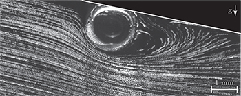
Fig. 3: Flow around an air bubble sliding under an inclined plate in water at  . Recirculation zone is clearly evidenced by the PIV particles trajectories.
Download figure:
Standard imageAs a consequence, the capillary force giving the spherical shape to the bubble is facing a hydrodynamic force that is inertial, as quantified by the Weber number
In the regime of  , this Weber number is, in our experiments, of the order of unity. So, in this situation the friction force has to be taken into account to describe the shape deformation. One can notice that the gravity effect is still also relevant because the Bond number is unchanged from the
  case. In conclusion, the bubble shape will be determined by the balance between surface tension, drag forces and gravity.
This regime is illustrated in figs. 2(d)–(f). These figures show a bubble of radius  sliding beneath a plane of various inclinations in a bath of distilled water
  . We can see that, for small bubble speed (i.e., small inclination), the bubble shape is basically a truncated sphere (see fig. 2(d)) because We is still low and gravity is dominating. As the bubble velocity increases, the friction does so and the bubble adopts a prolate shape fig. 2(f), which indicates
  , i.e., a shape resulting from balance between drag force and surface tension effects. This prolate shape is even more pronounced in fig. 4(a).

Fig. 4: Phase diagram for bubble shape in a (Bo,We)-plane. Different silicone oils and different bubbles radii are involved. Images are rotated such that the plate is horizontal, i.e., from an angle −θ (g vector indicates the vertical direction).
Download figure:
Standard imageAll this results can be summarized in a phase diagram (Bo, We) (see fig. 4). The dashed line is obtained for a perfect balance between hydrodynamical and hydrostatic contributions. For small volumes and small bubble velocities (i.e. small plane inclination and/or large viscosity), both terms are weak. A nearly spherical bubble is obtained (see fig. 4(d)). On the contrary, large volumes and velocities (obtained by increasing plane inclination angle or reducing bath viscosity) lead to bubbles both flattened and stretched (see fig. 4(b)) but non-symmetric. While the part of the bubble facing the flow is spherical, its back is tapered. This mainly results from the flow asymmetry, with a counterflow at the back of the bubble. Above the  dashed line, bubbles are stretched perpendicularly to the plane (see fig. 4(a)): hydrodynamic pressure is overpassing buoyancy. On the contrary, flattened bubbles are observed as far as hydrostatic pressure is dominating (see fig. 4(c)).
The regime  can also be recovered in this phase diagram by considering very small We when, as previously explained, only gravity matters. For small Bo, the bubble is almost circular (see fig. 4(d)) and for large Bo, the bubble appears as a truncated sphere or even as a puddle for the largest volumes (see fig. 4(c)).
Static description of the dynamic apparent contact
Below the inclined plate, the bubble is somehow squeezed by buoyancy facing capillary pressure. Since the bubble size is of the order of magnitude of the capillary length  , surface tension is important and the bubble shape stays close to a sphere. Nevertheless, the region of the bubble close to the plate is deformed and the air/liquid interface becomes parallel to the plate. This region, called "contact", is assumed as a disk with a radius L < R0 in the static case. This length is obtained by image analysis (see fig. 5).

Fig. 5: Image of a static bubble beneath an inclined plane. The "contact" region between the bubble and the plate is characterized by a linear air/liquid interface parallel to the plate and is 2L in diameter.
Download figure:
Standard imageAs reported in [22] two situations have to be considered in order to model this static case. First, if  , the bubble has a truncated sphere shape and its section is obtained by equaling the Archimede's and Laplace's pressures acting on the bubble. We thus have
If  , the balance between capillarity and gravity fixes the height of the bubble and the contact surface is obtained by conservation of the bubble volume. So L reads:
In fig. 6, we propose to plot this theoretical prediction, obtained with hypothesis of a static case, vs. the experimental data obtained in a non-static situation (i.e., when friction tends to reduce the value of L). A correct agreement is obtained for water even if the hydrodynamic pressure and the inclination angle of the plate are not considered in the modeling. A larger discrepancy is observed with silicone oils. This may arise from the small surface tension of oils. Indeed, highly deformed bubbles, such as fig. 4(a), experience a dominant hydrodynamic pressure reducing L value in a substantial way. This effect is larger for oils of low viscosity, as can be seen on the curve: for small viscosities the velocity is generally high and so the friction force has a larger effect on the bubble shape.

Fig. 6: (Colour online) Theoretical prediction for the "contact" length L (cf. eqs. (5) and (6)) vs. the experimental data for all tested liquids.
Download figure:
Standard imageConsidering the agreement between theory and experiments and in order to propose a model as simple as possible, we will consider in what follows, that eqs. (5) and (6) are relevant to predict the value of L in every situation.
Ascent dynamics
This description of bubble shape allows us to address the question of the bubble velocity v. As illustrated in fig. 7, this question appears to be non-trivial. In this figure, one can see the velocities of two bubbles of the same volume as a function of the tilt angle. The two bubbles are in two different liquid baths: highly viscous silicone oil and water. A factor higher than 20 in velocity between these two bubbles is noticeable, as well as an important difference in the dependence on the tilt angle θ. The existing models (especially models proposed by [22]) are not able to well describe both configurations.
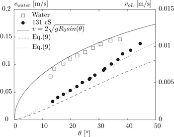
Fig. 7: Bubble velocity as a function of the tilt angle θ. Two configurations are shown here: an air bubble of  in water (blank squares) and an air bubble of
  in silicone oil 131 cS (black disks). The continuous curve (plotted on the vwater axis) is a prediction obtained in the fully inertial case, the dashed line (plotted on the voil axis) is a numerical inversion of eq. (9). Multiplying it by a pre-factor 1.3 gives the dotted line (see text for details).
Download figure:
Standard imageWe then propose here to approach the bubble velocity v with mechanical model as simple as possible.
The previous study of the phenomenology learned us the forces which have to be taken into account: Archimede's force as driving force, the friction and the creation of a dynamic meniscus as opposite forces.
The density difference between air and liquid, within the Earth gravitational field is the source of the ascent motion. Neglecting the density of air, this body force is given as  where
where  is the bubble volume.
The friction force is relevant but should be modelled by taking into account the influence of the Reynolds number. We then propose to model the friction by

with CD the drag coefficient. Following the most simple approach present in the literature (for instance in [29]) we consider

We choose:  in order to recover the limit case of a bubble without any contamination freely rising up in an infinite viscous bath [30] (using water may have a slight influence on α because the bubble surface is easily contaminated). This limit appears to be relevant in the case of a bubble sliding beneath an inclined plane as reported by Masliyah et al. [21]. β is let as a free parameter to be determined later. We thus have
 ![$C_D\in[\beta;660]$](https://content.cld.iop.org/journals/0295-5075/115/4/44001/revision1/epl18069ieqn48.gif) .
.
At the front of the bubble, a dynamic capillary meniscus is generated and connects with the "contact" region. As previously proposed by Aussillous et al. [22], this process is similar to a Landau-Levich tearing and, here, scales as  . Eventually, Newton's second law of motion for the bubble reads

where a and β were determined as follows. In a first time, we plotted eq. (9) for the data points of [22] (three angles ranging from 0.7° to 5.7° in a bath of silicone oil 1000 cS). In this case we chose  because the inertial friction can be neglected. We then obtained a value for the parameter
  . This value is coherent in order of magnitude with the value obtained in [22]. In this article, the authors fitted eq. (7) of this reference (valid for small bubbles) with two adjustable parameters and obtained for the one concerned here a value of 12. This factor between both values can be explained by the fact that we adjust data with only one free parameter.
Having determined a, we then adjust our data points varying β in order to obtain the best collapse. We obtain  (the limit case for a bubble freely rising up in an infinite bath at high Re is 2).
Figure 8 presents a comparison between the model eq. (9) and the experimental data, for all bubble radii, tilt angle values and for all the tested fluids. We also added the data extracted from [22]. With a = 9 and  , all the data points collapse on the master curve and so enforce the validity of the model.

Fig. 8: (Colour online) Test of eq. (9). The buoyancy force FA is balanced by the sum of the dynamics meniscus force FM and the inertial drag FI. The coefficient β is determined as the best value for collapsing the curves  . Experimental points appear to be well aligned on a linear function of slope unity. Insert: FA is balanced only by the meniscus force FM. This insert emphasizes the importance of the meniscus force in the experiment.
Download figure:
Standard imageOne can also observe that for large volumes (i.e., for high FA values) the discrepancy between our data and the model increases. This can be explained by the fact that we did not take into account the shape deformation neither for L nor for CD.
The agreement between data and our model is remarkable given that it is validated over four decades in Reynolds (seven if we take into account the data extracted from [22]) with both  and
and  and evidences the need to consider viscous force at the meniscus scale even at high Re. This need is also evidenced in the insert of fig. 8, where FM is plotted against FA.
Considering this agreement we can define three limiting regimes: when FM dominates, when the viscous drag dominates and when the inertial term dominates. The first one is well described in [22]. The second regime corresponds to a freely ascending bubble in a viscous fluid but with a reduced gravity, i.e.,  . This region is not encountered here. The inertia dominated regime gives
  and its relevancy is shown in fig. 7 without fitting parameters. The same figure presents a numerical inversion of eq. (9) in the intermediate case where both viscous drag and viscous meniscus matter
  . A direct inversion (dashed line) exhibits some discrepancy with the data points (also visible in the fig. 8) and a pre-factor 1.3 to the velocity (dotted line) is needed to fit them. This agreement between the model and the experimental tendency validates our approach.
Conclusion
We have performed series of experiments on the sliding motion of small bubbles beneath an inclined plane as a function of various physical parameters. The bubble shape strongly depends on the balance between capillary, gravity and hydrodynamic forces during the motion. In all cases, the dynamic meniscus is shown to play an important role in the drag experienced by the bubble and results in the generation of a thin lubrication film of typical length-scale L. Modeling this L parameter allowed us to propose an inertial model and to match the data points. The limits of this model have been drawn and open the way to studies with even larger bubbles, such as pancakes in the low viscous regime. A quantitative study for the bubble deformations (defining eccentricity or elongation parameters) could also be of interest.
Acknowledgments
We acknowledge University of Liège through the ARC SuperCool grant (reference ARC 11/16-03) for financial support, both in salaries and equipment. M. Mélard and S. Rondia are kindly acknowledged for their technical help.