

Abstract
A new extraction technique has been studied at the CERN Proton Synchrotron with a view of using it for the fixed-target physics programme at the Super Proton Synchrotron. The extraction scheme is based on advanced concepts of non-linear beam dynamics: prior to extraction a particle beam is split into several beamlets in a transverse plane by crossing a stable resonance, which allows extracting the beamlets over multiple turns. The principle of the extraction, the detail of its implementation, and the progress of the beam commissioning over the years are discussed here. More importantly, the results obtained during the first period of successful use for the physics programme are presented, focusing on the performance analysis of the novel extraction.
Export citation and abstract BibTeX RIS

Published by the EPLA under the terms of the Creative Commons Attribution 3.0 License (CC-BY). Further distribution of t his work must maintain attribution to the author(s) and the published article's title, journal citation, and DOI.
The proton beam for the fixed-target physics programme at the CERN Super Proton Synchrotron (SPS) [1] requires a very peculiar extraction scheme from the Proton Synchrotron (PS) at  . The SPS features a circumference that is eleven times that of the PS. In view of filling the SPS as fast as possible to increase the duty factor, two extractions from the PS are envisaged, each one stretching the effective beam length to five times the PS ring circumference. As a result, ten elevenths of the SPS ring are filled, while the remaining eleventh is left empty to accommodate the rise and fall time of the injection kickers. The PS extraction mode in operation until September 2015 was proposed in the early 70s [2,3] and has been successfully used ever since. It is named Continuous Transfer (CT) and is based on beam slicing in the horizontal plane across the thin foil of an electrostatic septum. The action of a closed fast bump, which is generated around the location of the electrostatic septum, moves the beam across the septum foil. The particles in the septum gap are deflected and, after performing betatronic oscillations along a large fraction of the PS circumference, are extracted by means of a magnetic septum. The value of the horizontal tune is set to
  , so that after each machine revolution the beam turns by 90° in the horizontal phase space. In this way, fresh beam enters into the gap of the electrostatic septum at each turn, which makes it possible to slice and extract the beam over five turns. The principle is sketched in fig. 1.

Fig. 1: (Colour online) Sketch of the principle of the CT extraction used in the PS since the 70s, including the elements used. Here and in the following the number close to the element name indicates the straight section where the element is installed.
Download figure:
Standard imageAlthough robust, this method has some severe drawbacks. Firstly, the slicing process implies that the beam-foil interaction generates high radiation levels at the location of the electrostatic septum and also in a large fraction of the PS circumference [4]. This is particularly worrisome in the case of high-intensity proton beams that might be needed for the SPS fixed-target physics programme [5,6]. Moreover, the betatronic matching at SPS injection is not optimal as each extracted beam slice features a different phase space shape, resulting in different optical parameters and emittances [7,8]. Alternative modes of extraction have been studied since the advent of the CERN Neutrino to Gran Sasso (CNGS) experiment [9].
A different beam manipulation was proposed in 2002 [10]. The principle is based on the use of stable islands of low-order 1D resonances of horizontal phase space. In fact, by adiabatically crossing a resonance excited by non-linear magnetic elements such as sextupoles and octupoles, it is possible to trap particles in the separating islands. If these islands are moved towards higher phase space amplitudes, the trapped beam will follow. An example of the evolution of the horizontal beam distribution is shown in fig. 2, in which the splitting process is simulated using a realistic model of the PS ring, whose parameters are varied according to the settings applied in operation.

Fig. 2: (Colour online) Simulated evolution of the horizontal beam distribution during the resonance crossing process performed according to the operational configuration shown in fig. 3.
Download figure:
Standard imageThe transverse trapping and transport process, which efficiently replaces the slicing performed with CT, is performed prior to and prepares for beam extraction. Beam extraction is performed by a set of fast dipoles generating a closed orbit deformation lasting five machine turns. The whole process, beam splitting and extraction, has been named Multi-Turn Extraction (MTE).
The time variation of the dedicated sextupoles and octupoles used to trap particles and of the RF voltage is shown in fig. 3 (upper panel), while in the lower part the variation of the key physical parameters is reported, assuming the following notation:
where δ and Jx, Jy are the relative momentum offset and the actions in the horizontal and vertical plane. The terms h2,0, h0,2, h1,1 represent the detuning due to non-linear motion in the horizontal, vertical plane, and the non-linear coupling between them [11].  are the n-th–order chromaticities. The coefficients appearing in eqs. (1) are functions of the strength of quadrupoles, sextupoles, and octupoles in the PS ring [11] and, e.g., in the case of octupoles, the functional dependence reads

where  , L being the length of the magnet, p/e the beam magnetic rigidity, and By the vertical component of the magnetic field.
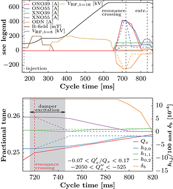
Fig. 3: (Colour online) Time evolution of the strength of the key families of sextupoles, octupoles, and of RF voltage during the resonance crossing process (upper panel). For sextupoles and octupoles the continuous curves correspond to the operational functions, and the dashed ones to simplified functions for special tests. The variation of the corresponding main observables of beam dynamics is also shown (lower panel).  is the bucket height and is equal to
  , with
  the rms beam momentum spread. The location of the main elements in the PS ring is shown in fig. 4.
Download figure:
Standard imageAssuming a weak coupling between the horizontal and vertical degrees of freedom, and neglecting the longitudinal degree of freedom, the motion in the horizontal plane close to the fourth-order resonance can be described by the following pendulum-like Hamiltonian [12]:

in which h2,0, u0,3 are functions of  with
with ![$t \in [0,t_\text{f}]$](https://content.cld.iop.org/journals/0295-5075/113/3/34001/revision1/epl17680ieqn9.gif) and
and  , expressing the variation of the linear tune around the resonant value (corresponding to t = 0) until the end of crossing at time
  , and κ, which is a function of the strength of sextupoles and octupoles. The main result of [12] is that the probability of trapping a particle in moving islands is proportional to the variation of the islands' surface and it scales with
  .
.
Sextupole and octupole magnets are used to generate the stable islands and to control their parameters, size and position, to maximise the trapping probability. The coupling between horizontal and vertical motion, which could negatively affect the overall trapping efficiency, is reduced by minimising h1,1 and the vertical emittance. In theory, the coefficients  should be minimised to reduce the coupling between transverse and longitudinal motion, but in practice only
  is controlled, the other parameters being left free.
The transverse resonance is crossed by changing the horizontal tune while keeping the vertical one constant. This variation is obtained by means of two families of quadrupoles that are distributed along the PS circumference. For 30 ms (one PS turn corresponds to  ) after the crossing of the 1/4 resonance the beam is excited horizontally by a wide band stripline kicker, used to provide an excitation at a frequency close to the resonant tune frequency. This has shown to improve the trapping probability into the stable islands. After splitting, the beam is made of two disconnected parts: the beamlets in the stable islands, which form a structure four machine-turn long and the beam core. This core is made of the particles left around the centre of phase space after resonance crossing and is only one machine-turn long.
As far as the longitudinal dynamics is concerned, the RF voltage,  , of the 10 MHz main cavity system is reduced before the resonance-crossing stage to minimise even further the coupling between the transverse and longitudinal degrees of freedom. After that,
  is set to zero to perform a complete de-bunching of the beam from the original h = 16 configuration. Prior to extraction a partial re-capture using a 200 MHz system is performed and the continuous beam, with an intensity modulation, is ready for transfer to the SPS where it will be re-captured using the 200 MHz main RF system.
The natural figure of merit of the MTE performance is

where  and
and  stand for the average intensity in the islands and the total beam intensity, respectively. The nominal efficiency is 20%, corresponding to an equal beam sharing between islands and core, with a minimum acceptable value of 19% set by the SPS.
Beam splitting has been studied in great detail (see, e.g., refs. [13–17]) and in 2006 it was decided to proceed with the implementation stage, starting with hardware design and construction [18]. The key elements for MTE are shown in fig. 4 (top), where the main lattice parameters ( and
and  ) are shown along the PS ring. A major review of the PS mechanical aperture was carried out and several vacuum chambers —both in straight sections and in main magnet units— were replaced with larger ones. This has been deemed necessary to accommodate the ensemble of beamlets and beam core, requiring more horizontal aperture with respect to a standard beam, particularly in the extraction region, as is shown in fig. 4 (bottom).
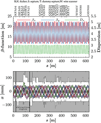
Fig. 4: (Colour online) Top: evolution along the PS circumference of the lattice functions, showing also the location of the essential elements for MTE. Bottom: horizontal ring aperture together with beamlets and core envelope just prior to the pulsing of the kickers. The extraction region indicates the section of the ring where orbit bumps are present.
Download figure:
Standard imageThe end of the installation phase and the ensuing hardware commissioning were accomplished in 2008 [19], while the beam commissioning, using low-intensity proton beams bunched on h = 16, was pursued at the PS and occasionally the extracted beams were delivered to the SPS for further studies and tuning [20]. In 2010, the PS start up was performed using MTE, whereas CT was kept as a fall back option. At that time, high-intensity proton beams were delivered to the SPS for a few weeks only, as two outstanding issues were limiting the overall MTE performance [21], as both  and the extraction trajectories were fluctuating on a cycle-by-cycle basis. This was not only affecting significantly the beam transmission through acceleration in the SPS, but also preventing a proper optimisation of SPS parameters. Figure 5 shows examples of these fluctuations: the transverse beam distribution changes completely (left), which in turns generates a difference in the extracted spill profile (right) without any apparent change of the ring parameters.

Fig. 5: (Colour online) Left: measured horizontal beam distribution for nominal and lower-than-nominal  . Right: corresponding intensity profile measured by a beam current transformer in the transfer line between PS and SPS.
Download figure:
Standard imageThe second issue was the activation of the PS extraction region, which had increased due to the debunched beam and the long rise time of the kickers, although a significant reduction of the radiation levels compared to CT operation was observed in the rest of the ring.
Intense investigations were undertaken to find the source of the observed variations and to overcome the PS ring activation. A so-called dummy septum, a sort of passive septum with only a copper blade and no coils for the generation of a guiding magnetic field, was designed to tackle the increased activation. The dummy septum intercepts protons that would otherwise interact with the blade of the active extraction septum during the extraction kickers' rise time. This approach, combined with an appropriate shielding of the device, provides a well-localised loss point that is acceptable in terms of overall PS ring activation. The use of a shadowing device for the main extraction septum is a known approach in, e.g., the SPS. However, in a small ring like the PS the two devices can hardly be located next to each other, making the configuration more complicated in terms of beam dynamics. Moreover, a side effect of the dummy septum solution is that the horizontal PS ring aperture is reduced, which called for a complete review of all PS fast extraction schemes to make them compatible with the dummy septum [22–25]. This additional hurdle was overcome and during the Long Shutdown 1, lasting from February 2013 to May 2014, the construction and installation of the dummy septum was completed [26]. The beam commissioning of the whole system and of the new fast extractions was successfully accomplished by the end of 2014.
The first positive result from a long and detailed measurement campaign aimed at finding a physical quantity well correlated with the fluctuations of  was obtained at the beginning of the 2015 run. The control of the PS working point, i.e., of Qx,y and
  , is achieved by means of special circuits, the pole-face-winding (PFW) coils and the figure-of-eight loop (F8L) as reported in ref. [27] and references therein. These circuits power additional coils installed on the poles of the combined-function main dipoles and allow the generation of a transverse variation of the magnetic field, which can be used to generate quadrupolar, sextupolar, and octupolar magnetic-field components. The switch-mode power converters operate at 5 kHz (for the PFWs) and 2.5 kHz (for the F8L) and they introduce a current ripple at that frequency. The amplitude of such a component turned out to be larger-than-expected and not constant in time. The latter issue is a consequence of the lack of synchronisation of the clocks of the power converters of the different circuits. The main effect of such a ripple is to change the machine parameters and hence to alter the overall efficiency of the MTE process. The very good correlation between the cycle-to-cycle variation of the transverse beam distribution after splitting and of the 5 kHz ripple amplitude is shown in fig. 6.
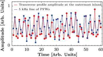
Fig. 6: (Colour online) Time evolution of the transverse beam distribution after splitting (i.e., distribution amplitude at the location of the outermost island) and of the amplitude of the 5 kHz component in the PFWs current.
Download figure:
Standard imageThe performance of the PFWs circuits was then improved damping the 5 kHz ripple component. As expected, this reduced the amplitude of the fluctuations of  , thus opening again the possibility to transfer MTE beams to the SPS for the fixed-target physics, which has been done successfully in 2015, from September 21st until the end of the proton run on November 16th. During this lapse of time, continuous beam optimisation was carried out, including also intensity increase, from
  per PS extraction at the beginning of November to
  , passing by an intermediate value of
  . By the end of the run, the dummy septum had been moved to its nominal position to properly shadow the extraction septum.
The dummy septum was set up in two steps: firstly its blade was positioned to maximise the extraction efficiency  ; secondly, the magnetic septum was moved to minimise the extraction losses. This step was accomplished by means of a fast beam loss monitor (BLM) placed on top of the magnetic septum providing the information about beam losses with a time resolution better than a turn. An example is shown in fig. 7 (left) together with the evolution of extraction losses vs. septum position (right).

Fig. 7: Left: extraction losses on the magnetic septum as measured by a fast BLM. The two peaks refer to the losses during the rise time of the kickers for the islands and the core, respectively. Right: loss optimisation by changing the position of the magnetic septum using the sum of the amplitudes of the loss peaks as figure of merit.
Download figure:
Standard imageThe evolution of beam intensity and  is shown in fig. 8, where the beam intensity refers to that of the circulating beam prior to extraction, while
  is computed comparing this value to that measured by a beam current transformer in the transfer line just downstream of the PS extraction point.

Fig. 8: (Colour online) Evolution of PS proton intensity prior to extraction and of  for the 2015 MTE run. The main events and the periods selected for the statistical analysis are marked.
Download figure:
Standard imageNo measurable beam losses occur during the beam splitting process according to the results of the numerical simulations and theoretical predictions [18]. Another crucial aspect to consider is the distribution of beam losses around the PS ring. Figure 9 shows the results of the measurements performed by the BLMs located around the PS circumference in the 100 straight sections: the difference between CT and MTE is striking and fully confirms the predictions of the MTE performance.
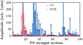
Fig. 9: (Colour online) Distribution of extraction losses for CT and MTE around the PS ring. MTE is clearly cleaner, with losses localised around the extraction region only. The BLM installed at the dummy septum is the only one saturated.
Download figure:
Standard imageFor MTE  is around 97–98%, whereas a typical value of
  for CT at similar beam intensity is around 95%. Hence, MTE reduces extraction losses with respect to CT by almost a factor of 2. The distributions of
  and
and  for the three intensities used in 2015 are shown in fig. 10, together with the cumulative distributions of
  and the correlations for
  and
and  . A summary of some statistical indicators is listed in table 1.

Fig. 10: (Colour online) Top: distributions of  (left) and their cumulative distributions (right). Bottom: distributions of
  (left) and correlation plot for
  and
and  (right).
Download figure:
Standard imageTable 1:.
 and
and  for the 2015 beams (operational variants and special one). The mean (μ), median (Q2), and standard deviation (σ) are quoted.
| Beam type | Intensity |  |
 |
||||
|---|---|---|---|---|---|---|---|
| (1013) | μ | Q2 | σ | μ | Q2 | σ | |
| 1.5 | 19.96 | 19.99 | 0.56 | 97.61 | 97.69 | 0.75 | |
| Operational | 1.8 | 19.72 | 19.75 | 0.55 | 97.71 | 97.79 | 0.69 |
| 2.0 | 19.90 | 19.92 | 0.41 | 97.50 | 97.56 | 0.60 | |
| Special test | 1.5 | 19.97 | 20.00 | 0.42 | 99.28 | 99.37 | 0.53 |
The statistical correlation for  and
and  with beam intensity proved to be close to zero, which is an interesting result as the overall trapping performance could be potentially sensitive to space charge effects [28]. The distributions shown in fig. 10 seem to indicate a mild dependence on intensity. They have been checked pairwise against the hypothesis that they are equal and the statistical analysis rejected it with a confidence level of 95%, confirming that the visible differences are meaningful and, as these cannot be linked with intensity, are indeed the effect of the PS machine fine tuning throughout the run.
All distributions are asymmetric featuring tails towards the lower side, which is reflected by the difference between mean and median. Moreover, a non-negligible number of outliers is present, which has an impact on the statistical parameters listed in table 1. From the reconstructed cumulative distribution of  , information about the fraction of non-conforming cycles has been obtained. Such a piece of information will guide the research of further improvements of the MTE reproducibility. The correlation plot reveals a link of average strength between
  and
and  . Several mechanisms could explain this fact, such as for lower-than-nominal
  either a halo around the beam at the centre is generated or the beam at the centre grows in size. During extraction the halo or the grown central beam would generate losses, thus reducing
  . Additional measurements are planned during the 2016 run to clarify this point.
In parallel to the activities for making MTE operational, studies have been carried out to further improve the MTE reproducibility. The first step has been the use of simplified functions (see fig. 3 —dashed curves), which have been used to collect data over 103 cycles to check the overall performance of this special configuration. The results are shown in fig. 10 as the grey distributions and are also listed in table 1. Note that during these measurements small variations of the strengths of the dedicated MTE sextupoles were made, which proved to be completely irrelevant in terms of  and
and  . The difference with respect to the operational variant of the MTE beam is clearly visible, featuring an impressive improvement in
  . The distribution of
  is also more symmetric and centred around 20%. A statistical check has been carried out to compare the meaningfulness of the differences of
  for operational and special beams of corresponding intensity. The key point is that the symmetry could have been generated by the lack of long tails because of the limited statistic. Nonetheless, drawing several randomly generated subsets of 103 cases out of the total number of cases for the operational beam, the statistical tests to check whether the two
  distributions are the same rejected this hypothesis at 95% confidence level. These successful tests will be pursued in 2016 including also scans of the strength of the octupoles to assess any beneficial impact on the overall reproducibility of MTE. Finally, given the already proven impact of power converters' performance on MTE stability, several studies are planned in 2016 in view of devising further improvements to the PFWs such as a new electronic, which could allow the suppression of the observed ripple at 5 kHz.
Acknowledgments
We would like to thank R. Steerenberg and the CERN PS Operations crew for the help provided, G. Arduini and J.-P. Burnet for the constant support, and A. Bazzani, A. Franchi, and G. Turchetti for enlightening discussions. Special credit goes to R. Cappi, one of the originators of the proposal to replace the CT with an extraction based on transverse beam splitting, K. Hübner, and J.-P. Riunaud, for the key role played at the beginning of this enterprise.