Abstract
Multilayer coatings having a thickness of 18–22 μm consisting of different Ni, Ni-B alloys and Ni-B-PTFE composite layers were produced on steel by combining electroplating with electroless dynamic chemical plating (DCP). The individual Ni layers and the multilayer coatings (Ni/Ni-B and Ni/Ni-B/Ni-B-PTFE) were characterized by scanning electron microscopy (SEM), electrochemical polarization measurements and salt spray tests. The Ni coatings presenting high corrosion resistance (6000 h, ASTM-B117) were obtained by electrodeposition from a sulfamate bath containing a samarium salt, whereas Ni-B layers of high hardness (700 to 800 HV) were produced by both methods (electroplating and DCP). Composite Ni-B-PTFE coatings (≈14% volume of PTFE) of high hardness (≈600 HV) and low friction coefficient (0.4 to 0.5) were obtained by the DCP technique. A duplex Ni(10.6 μm)/Ni-B (12μm) coating produced by electrodeposition exhibited a total hardness of 618 ± 9 HV and corrosion resistance higher than 1369 h in the salt-spray test. Combining electrodeposition with DCP produced a three-layer Ni (8 μm)/Ni-B (2.5 μm)/Ni-B-PTFE (7.8 μm) with high corrosion resistance and proper hardness as well as a low coefficient of friction.
Export citation and abstract BibTeX RIS

This is an open access article distributed under the terms of the Creative Commons Attribution 4.0 License (CC BY, http://creativecommons.org/licenses/by/4.0/), which permits unrestricted reuse of the work in any medium, provided the original work is properly cited.
Hard chromium coatings on steel, generally obtained by electrodeposition provide excellent properties such as high resistance to corrosion (200 to 800 h in saline spray) and excellent hardness (800 to 1000 HV) and a low coefficient of friction (0.12 to 0.25).1--3 Due to environmental issues related to the toxicity of the hexavalent chromium salts used during the electrodeposition processes,4,5 much research has been undertaken to develop coatings to replace the hard chrome surfaces. These new films should present a corrosion resistance exceeding 500 h in the saline chamber, a hardness value greater than 500 HV and a coefficient of friction near 0.2. Within this context, monolayer and multilayer coatings based on nickel and copper have been studied to obtain protective coatings with the desired physical and chemical properties.6–15
Several studies have been reported in the literature regarding coatings of mono and multilayer Ni-P films obtained mainly by electroless deposition. Evaluation of microhardness, wear, and corrosion resistance showed primarily excellent resistance to corrosion.16,17 Different studies have been made of mono and multilayer Ni-B coatings involving electroplating and electroless and dynamic chemical plating (DCP).18–20 Ni-B layers obtained by electrodeposition using dimethylamine borane (DMAB) combined with thermal treatment yielded a high resistance to corrosion, good adhesion, and a low wear-rate coefficient.18 In the case of Ni-B films obtained by electroless deposition using borohydride, it was determined that heat-treatment favors the enhanced hardness and wear resistance.19 Research has also been carried out on Ni-B layers and Ni-B-Graphite and Ni-B-PTFE composites formed by dynamic chemical plating, a modified electroless coating process which provides an alternative technique for producing metallic deposits on non-conductive materials.20
In this study, bi-layer Ni/Ni-B and Ni/Ni-B/Ni-B-PTFE tri-layer coatings on steel were obtained combining electroplating and dynamic chemical plating techniques. Structure, composition, corrosion resistance, and hardness were evaluated by scanning electron microscopy (SEM), plasma emission spectroscopy (ICP), voltammetry, and salt-spray tests. A tri-layer Ni/Ni-B/Ni-B-PTFE coating was produced that provides resistance to corrosion for more than 1000 h in a salt-spray chamber, hardness ≈ 600 HV and a coefficient of friction of approximately 0.4.
Experimental
Coatings obtained by electroplating
The Ni and Ni-B coatings were produced by electroplating in an acrylic rectangular cell of the following dimensions 70 × 70 × 100 mm. A steel sheet cathode, AISI 1006 (0.074% C, 0.004% S, 0.008% P, 0.245% Si, 0.174% Mn) of dimensions 65 × 70 × 1 mm. served as the cathode. The anode was a (high purity) nickel sheet of dimensions 70 × 100 × 2 mm.
Before performing the deposition process, the steel substrate was prepared by alkaline degreasing, rinsing, and acid pickling as follows. Alkaline degreasing: Immersion of the steel plate in a NaOH solution (60–70 g/L) at a temperature of ≈80°C for 7–10 min. Acid pickling immersion of the plate in a sulfamic acid solution (30 g/L) at room temperature for 15 s. This step must be carried out just before starting the deposition process to avoid the formation of oxides on the surface of the steel plate. Table I shows the composition of the electrolytic baths and operating conditions used to prepare the coatings by this technique.
Table I. Composition and operating conditions of electrolytic baths used for the preparation of Ni based coatings.
| Composition and operating conditions | Ni | Ni(Sm) | Ni-B |
|---|---|---|---|
| Nickel sulfamate | 400 g/L | 400 g/L | 400 g/L |
| Boric acid | 40 g/L | 40 g/L | 30 g/L |
| Commercial surfactant | 3--6 mL/L | 3--6 mL/L | 3--6 mL/L |
| Sodiumdodecyl sulfate (SDS) | 0.05--0.08 g/L | 0.05--0.08 g/L | — |
| Samarium sulfate | — | 24.6 mM like Sm3+ | — |
| Dimetylamineborane (DMAB) | — | — | 3 g/L |
| pH | 1.5−2 | 1.5−2 | 2.5--3.0 |
| Temperature | 55°C | 55°C | 45°C |
| Current density | 30 mA/cm2 | 30 mA/cm2 | 30 mA/cm2 |
| Mechanical agitation | 350 rpm | 350 rpm | 350 rpm |
Coatings obtained by dynamic chemical plating (DCP)
Layers of Ni-B and Ni-B-PTFE were prepared by the DCP technique using a commercial spray gun with a double spray nozzle (DeVilbiss-AGPV2K). The substrate, previously cleaned (by alkaline degreasing and acid treatment), was placed on a rotating support and rinsed with deionized water. Then, two solutions (oxidant and reductant) were projected by the jets on to the surface of the steel substrate. This projection is made intermittently with the objective of having better chemical-reaction efficiency. The solutions were projected for 1.7 swith a flow of 22 mL/min, followed by a 0.5 s pause. The scheme of the experimental device can be seen in Figure 1, and the solutions used are shown in Table II.

Figure 1. Scheme of the device used for the metallization process using the DCP technique (JetMetal).
Table II. Composition of the solutions used to obtain deposits of Ni-B and Ni-B-PTFE by DCP technique.
| Solution | Ni-B coating | Ni-B-PTFE coating |
|---|---|---|
| Oxidant | 10 g/L NiSO4 additives pH = 7.1 T = 25°C | 10 g/L NiSO4 5, 7.5, 10 y 15 mL/L of PTFE (60%) emulsion additives pH = 7.3–7.5 T = 25°C |
| Reducer | 10 g/L KBH4 pH = 11--12 | 10 g/L KBH4 pH = 11--12 |
Coatings characterization
The morphology of the coatings was observed by electron scanning microscopy using a JEOL-5400LV microscope.
The boron content in the NiB coatings was determined by plasma emission spectroscopy (ICP). The deposits were formed on the stainless steel substrate and then were separated mechanically and dissolved in nitric acid for elemental analysis. For example, a deposit mass of 0.307 g was dissolved in 10 mL of concentrated HNO3 and then diluted with deionized water to 50 mL. The concentration of B in the solution was determined by ICP and used to calculate the boron percentage in the coating. In this way the boron content was found to be 1.85% by weight for the electrodeposited NiB and 7.6% by weight for NiB obtained by dynamic chemical plating.
For NiB-PTFE coatings, the fluorine content was determined by energy dispersive spectrometry (EDS or EDX) over the surface of the sample. The elemental fluorine content was converted to PTFE wt% in the deposit based on the fluorine content in Teflon (C2F4).
The corrosion resistance of the various films was evaluated by use of voltammetric polarization curves and salt-spray tests. The polarization curves were obtained using a PAR 263A potentiostat and a three-electrode glass cell (Princeton Applied Research, Model K0235) with a volume of 250 mL and an exposed sample area of 1 cm2. A platinum mesh and a saturated calomel electrode (SCE) were used as auxiliary and reference electrodes, respectively. The potentiodynamic polarization tests were conducted in a 5% NaCl solution at 25°C with a sweep rate of 0.17 mV/s (based on the ASTM G5 standard).21 Before polarization, the samples were allowed to stabilize for two hours in the electrolyte to obtain a stable open-circuit potential (OCP). All experiments were performed in duplicate to confirm reproducibility.
Saline-chamber exposure tests were performed according to the ASTM B117 and the ISO 10289 standards22,23 in a Q-FOG CCT-600 chamber. The size of the samples used in this test was 65 × 70 × 1 mm, and the criterion for determining coating failure was the first observed presence of red corrosion product.
The microhardness tests were made over the surface of the samples using a Matsuzawa MXT-Alfa micro durometer, according to the ASTM E384-1124 and ASTM E92-8225 procedures. For each sample, measurements were performed at ten locations to obtain an average value. This test consists of forcing a pyramid-shaped diamond indenter (with an angle between faces of 136°) into the surface of the material being evaluated with an applied force ranging from 1 to 1000 gf and to measure the width of the resulting impression formed by the load. Based on a simple analysis of solid deformation mechanics, the Vickers hardness (HV) is determined from the measurement of the indentation width with an optical microscope and the value of the applied load according to the following equation:24

where:
HV = Vickers hardness value, P = Applied load (gf), d = mean diagonal width of the indentation (μm).
For thin films the simple, single-material model is not accurate as the properties of the underlying substrate can affect the film deformation. As higher loads cause deeper penetration of the diamond stylus, apparent hardness values will deviate from an intrinsic film property as the indentation approaches the underlying substrate. Thus, one must recognize a limited range of valid measurements depending on the film thickness and the applied force. That is, hardness measurements should be limited to conditions where the indentation depth is less than the film thickness. The depth (h) of the indentation print is related with the diagonal width (d) of the print according to the following equation:
where:
h = Depth of the print generated by the pyramidal indenter (μm) and d = Mean diagonal width of the indentations (μm).
The minimum required thickness to minimize the substrate effect on the hardness measurement depends on the hardness of the material. Based on these considerations, for the measurements of individual layers of Ni(Sm) and NiB obtained by electroplating, films of 18 μm thickness were tested with an applied load of 100 gf.
For the NiB and NiB-PTFE coatings obtained by DCP, a thickness of approximately 12 μm was obtained, and a load charge of 100 gf was similarly applied. In this case, it was not possible to obtain greater thicknesses due to limitations of the technique. For these coatings, measurements were made in a zone located at a distance of approximately 20 μm from a microfissure; in the cases where a crack was generated during the test, its measurement was discarded.
The coefficients of friction for NiB-PTFE depots were determined using a ball-surface tribometer at ambient temperature and in normal atmospheric conditions. Specimens were rotated at 100 rpm while being exposed to a steel ball with 12.7 mm in diameter. The ball was made of 100C6 steel with a hardness of HRC 62.
Results and Discussion
Preparation of Ni-based coatings by electroplating
The Ni(Sm) and NiB depots was prepared by using a sulfamate electrolytic bath with samarium and DMAB additives. The composition and operating conditions are summarized in Table I. The addition of samarium (Sm3+) in the electrolytic bath was for the purpose of obtaining a nickel coating with better corrosion resistance, while the DMAB was incorporated in order to obtain a NiB coating with high hardness. Figure 2 shows the morphology of the deposit surfaces, and the cross-sections of Ni electrodeposited films using the bath with samarium (a, c) and the bath with DMAB (b, d). Ni layers produced in the presence of samarium reveal a homogeneous surface with pyramid-shaped grains, which is the typical morphology observed for Ni coatings produced from sulfamate baths.26,27 The deposits of Ni-B (1.85 wt% B) obtained from the bath with DMAB show a homogeneous surface with fine grain size but with the presence of micro-fissures, generated by high internal stress during its preparation. These micro-fissures in Ni-B coatings obtained by electrodeposition were also observed by Krishnaveni et al.28 As can be seen in the SEM image of the cross-section of this film (Figure 2d), the fissures extend from the surface of the deposit to the substrate. This fact suggests that these coatings will provide poor protection of a steel substrate against corrosion, considering that the substrate will be easily exposed to an aggressive environment.

Figure 2. SEM images (2000X) of the surface [a) Ni(Sm), b) Ni-B] and of the cross section [c) Ni(Sm), d) 5 Ni-B] of Ni electrodeposits.
Evaluation of corrosion resistance
Polarization curves obtained for Ni, Ni(Sm) and Ni-B (1.85 wt%) films are shown in Figure 3, and the corrosion current densities (jcorr) and potentials (Ecorr) obtained by Tafel interpolation are given in Table III. It can be seen that the Ni coatings obtained from the bath with samarium showed a corrosion potential of −0.158 V vs. SCE, and the corrosion current density was 0.07μA/cm2. These values correspond to the most positive corrosion potential and the lowest corrosion current density compared to the Ni-B and Ni films produced in the absence of samarium, indicating that it offers the best resistance to corrosion. The incorporation of samarium in the electrolytic bath produces a compact coating, free of cracks and favors the formation of a passive layer with greater resistance to attack.

Figure 3. Polarization curves for Ni, Ni-B and Ni(Sm) films obtained by electroplating.
Table III. Electrochemical parameters obtained from the polarization curves.
| Sample | Ecorr (V vs SCE) | jcorr (μA/cm2) |
|---|---|---|
| Substrate (steel AISI 1006) | −0.698 | 11.69 |
| Ni | −0.314 | 8.15 |
| Ni (Sm) | −0.158 | 0.07 |
| Ni-B (1.85 wt% B) | −0.532 | 10.37 |
The Ni-B film exhibited a corrosion potential of −0.532 V vs SCE and the corrosion current density was 10.37 μA/cm2; these parameters indicate that this coating does not provide good resistance to corrosion, presumably due to the presence of the cracks seen in the SEM image of the cross-section of this deposit (Figure 2d).
To complement the electrochemical corrosion tests, the films were also evaluated by exposure to a salt spray. The time at which the red corrosion products (PCR) are first observed is used to define failure of the film. The results obtained confirm that the corrosion resistance of Ni(Sm) endures for more than 6000 h while the Ni-B coating has a corrosion resistance that lasts for only 24 h (see Figure 4 and Figure 5). These results confirm the results of the polarization tests that indicated that the corrosion resistance of the coating of Ni (Sm) is much higher than that of the Ni-B deposits.

Figure 4. Results obtained by exposure in salt spray chamber for Ni, Ni-B (1.85% B) and Ni(Sm) films.

Figure 5. Photographs of samples after accelerated tests for corrosion resistance; a) Ni, b) NiB and Ni(Sm) films.
Hardness evaluation
Figure 6 shows the results of the hardness tests for the substrate and the Ni, Ni (Sm) and Ni-B films. Those results indicate that the coatings of Ni obtained in the presence of samarium present a hardness value of 289 ± 6 HV, very similar to the Ni coatings obtained in the absence of additives (211 ± 3 HV); these low hardness values are a characteristic property of Ni coatings obtained from a sulfamate bath due to its low internal stress. In contrast, the Ni-B film obtained from the bath with DMAB exhibits a higher hardness value, 716 ± 22 HV. Furthermore, the hardness of these film can be enhanced by heat-treatment at 350°C for one hour as shown in previous works.29

Figure 6. Hardness and thickness values obtained for the different samples: Ni, Ni-B (1.85% B) and Ni(Sm) films.
Preparation of Ni-B and Ni-B-PTFE coatings by dynamic chemical plating
Ni-B layers were prepared on a steel substrate using a spray gun in an intermittent DCP mode with an oxidant solution containing various concentrations of a PTFE emulsion from Sigma Aldrich with 60% by weight of PTFE particles, at sizes ranging from 0.05 up to 0.5 microns (0.23 micron average).
Figure 7 shows the deposition kinetics of a Ni-B-PTFE coating as a function of the composition of the oxidant solution used for its preparation. It can be observed that the deposition rate decreases with an increase in the concentration of PTFE in the oxidant solution. For a layer obtained from a solution with 5 mL/L of PTFE emulsion, of the rate was 7.3 μm/h; this deposition rate decreases by approximately 10% for the coating obtained from a solution with 10 or 15 mL/L of PTFE emulsion. The presence of PTFE in the solution interferes with the Ni reduction reaction. This inhibition probably comes from the fact that the PTFE particles carried by the oxidizing solution to the surface of the substrate are trapped in the liquid film, introducing a geometrical obstacle for the Ni2+ ion diffusion to the surface. A portion of the particles is adsorbed on the surface, while the rest drains with the effluents from the sample. The reduction in rate could also be attributed to the presence of surfactants used to stabilize the particles in the suspensions. These have a strong tendency to inhibit the redox reaction.20

Figure 7. Deposition rate for a Ni-B-PTFE coating as a function of the PTFE emulsion concentration added to the oxidizing solution.
Composition and morphology of Ni-B and Ni-B-PTFE
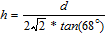
To estimate the concentration of PTFE in the film, fluoride determinations of the deposits were carried out using X-ray dispersive energy spectroscopy (EDS). The percentage of fluorine obtained by analysis was converted into % weight of PTFE based on the composition of fluorine in Teflon (C2F4). Figure 8 shows the composition in PTFE (% weight) for each film as a function of the concentration of the PTFE emulsion in the feed solution. This curve shows that the concentration of PTFE in the deposit increases with the concentration of the emulsion in the feed solution until it reaches a maximum value at a concentration of 10 mL/L of PTFE emulsion. At an emulsion concentration of is 15 mL/L, the concentration of PTFE in the coating decreases. This may be due to PTFE particle agglomeration at a high concentration of PTFE (>10 mL/L PTFE emulsion in solution). Agglomerated PTFE particles may not have time to be incorporated into the deposit because of their excessive size. They can be drained away with the effluents by gravitational force.
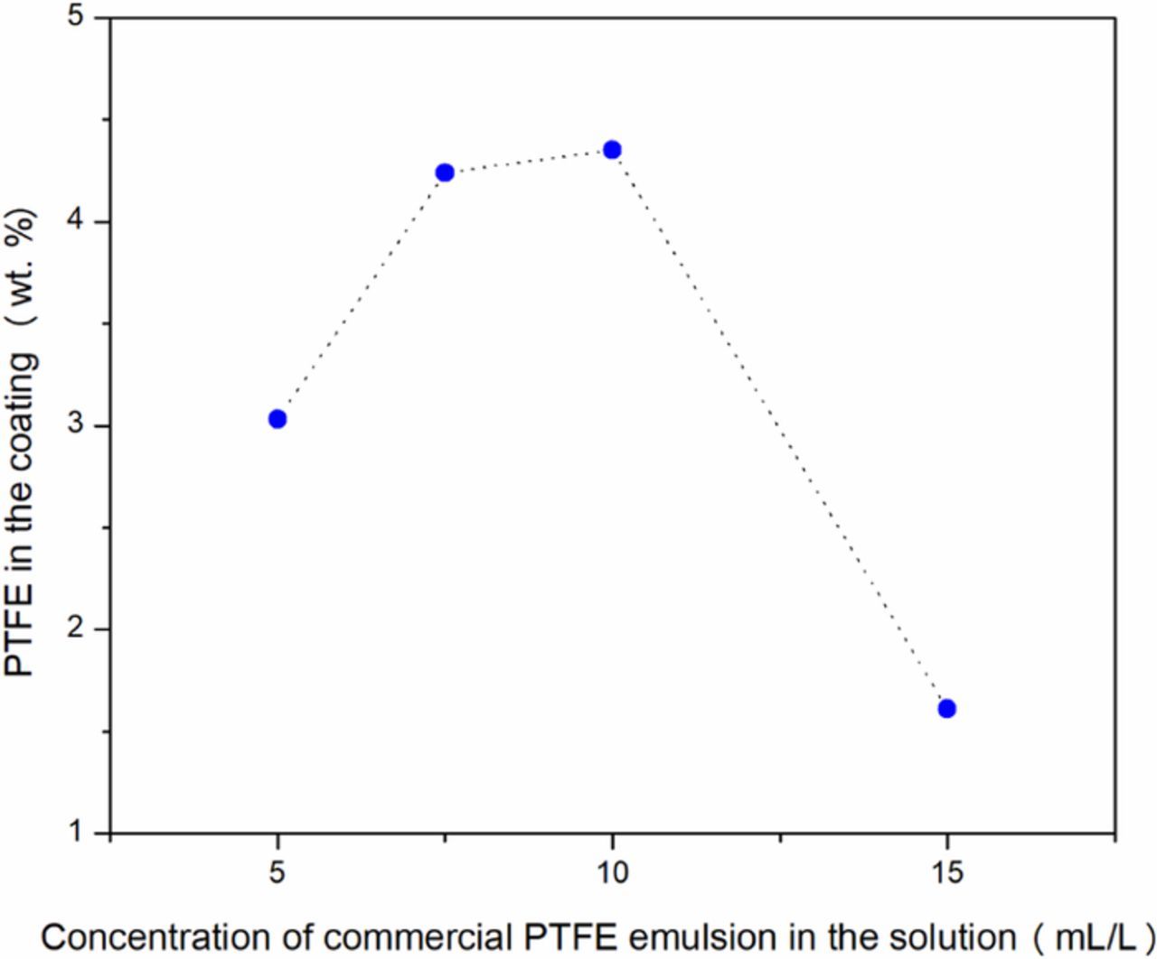
Figure 8. Ni-B-PTFE coatings composition as a function of the concentration of the PTFE emulsion in the oxidant solution.
Figure 9 shows the SEM image of the surfaces of a Ni-B coating without PTFE and of a Ni-B-PTFE film (4.4 wt % PTFE). These coatings show a similar morphology with granular growth and the presence of fissures. The main difference between the morphology of the two surfaces is that the Ni-B-PTFE coating surface shows two distinct zones, one very compact and another area less compact with the presence of cracks, probably due to PTFE in the coating. The formation of fissures in these films is due to high internal stress generated during their preparation and can diminish the anti-corrosion performance of these coatings, as was observed with the Ni-B deposits obtained by electroplating. The characterization of NiB-PTFE composite films prepared by DCP was reported in previous works where a homogeneous distribution of PTFE particles with an average size of 0.2 μm was found.20
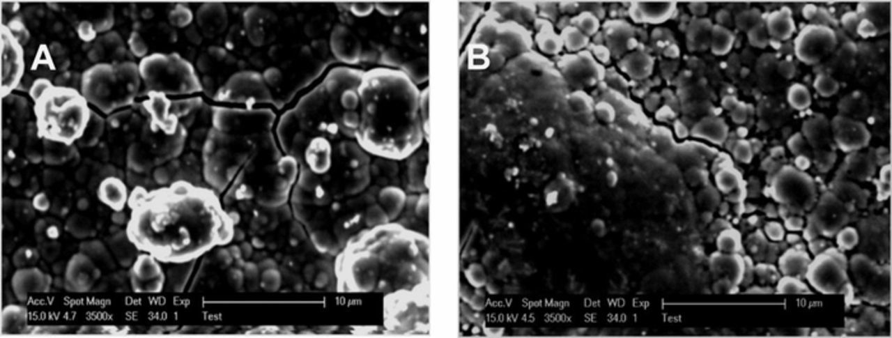
Figure 9. SEM images (3500X) of: a) Ni-B coating (0% PTFE) and b) Ni-B-PTFE coating (4.4 wt% PTFE) obtained using an oxidizing solution without PTFE and with 10 mL/L of PTFE.
Evaluation of corrosion resistance
Figure 10 shows the voltammetric polarization curves for the substrate and for the NiB film obtained by DCP. It can be seen that NiB deposits obtained by this technique exhibit a corrosion potential of −0.652 V vs SCE and the corrosion current density is 11.16 μA/cm2. These values are very similar to those obtained with the Ni-B coatings fabricated by electrodeposition, indicating that neither of the NiB coatings obtained by either technique (electrodeposition and dynamic chemical deposit) are deficient for protection against corrosion.

Figure 10. Polarization curves for the substrate and Ni-B film obtained by Dynamic Chemical Plating (JetMetal).
The corrosion resistance of the NiB and Ni-B-PTFE coats made by DCP was also evaluated by exposure in the salt spray chamber; the results obtained are shown in Figure 11 and Figure 12. All the films presented red corrosion products in the first 24 hours of exposure.

Figure 11. Results obtained by exposure in a salt spray chamber for coatings: Ni-B and Ni-B-PTFE (4.4 wt% PTFE).

Figure 12. Pictures of deposits after accelerated tests for corrosion resistance: a) NiB and b) NiB-PTFE.
Hardness of Ni-B and Ni-B-PTFE coatings
The hardness measurements (Figure 13) indicate that the Ni-B film produced by the use of an oxidizing solution without PTFE has a hardness value of approximately 873 ± 179 HV while the hardness of the film Ni-B-PTFE (4.4% PTFE) was 556 ± 56 HV. Thus, the incorporation of PTFE in the coats seen to reduce the hardness of Ni-B deposits, but it also decreases the coefficient of friction improving the wear resistance. A Ni-B-PTFE coating containing ≈ 5% by weight of PTFE (14–15% by volume of PTFE) has a coefficient of friction of 0.4--0.5.20
Figure 13. Hardness values obtained for coatings of Ni-B and NiB-PTFE (4.4 wt% PTFE) obtained by JetMetal technology.
As shown previously was verified the presence of cracks in these NiB coatings limits their performance as an anti-corrosion barrier. On the other hand, however, the DCP technology produces Ni-B coatings with a high hardness (500 to 800 HV) and NiB-PTFE composite coatings with relative ease, similar to a painting process.
Preparation of a bi-layer Ni (Sm)/Ni-B coating by electroplating
From the above results, it can be seen that it is not easy to obtain a single-layer coating that possesses both corrosion resistance and high hardness. Accordingly, it has been proposed to manufacture a bi-layer coating Ni (Sm) /Ni-B on steel that combines these two properties. Such a deposit was obtained through the successive application of two electrolytic baths with the composition and operating conditions indicated in Table I. First, a nickel layer of approximately 10.6 μm was prepared on a steel substrate using the electrolytic bath with samarium. Then, on this film, a Ni-B deposit of 12 μm was made using the electrolytic bath containing DMAB.
The cross-section of a resulting steel/Ni(Sm)/Ni-B film is shown in Figure 14. The image shows the sublayer of Ni (Sm) coating the substrate and on it the outer layer of Ni-B (1.85 wt% B). Both layers are homogeneous and compact in some areas (see Figure 14a), but there are zones of the coating where cracks can be observed in the Ni-B layer (see Figure 4b). It is significant, however, to note that these fissures do not reach the substrate but extend only to the Ni(Sm)/NiB interface.
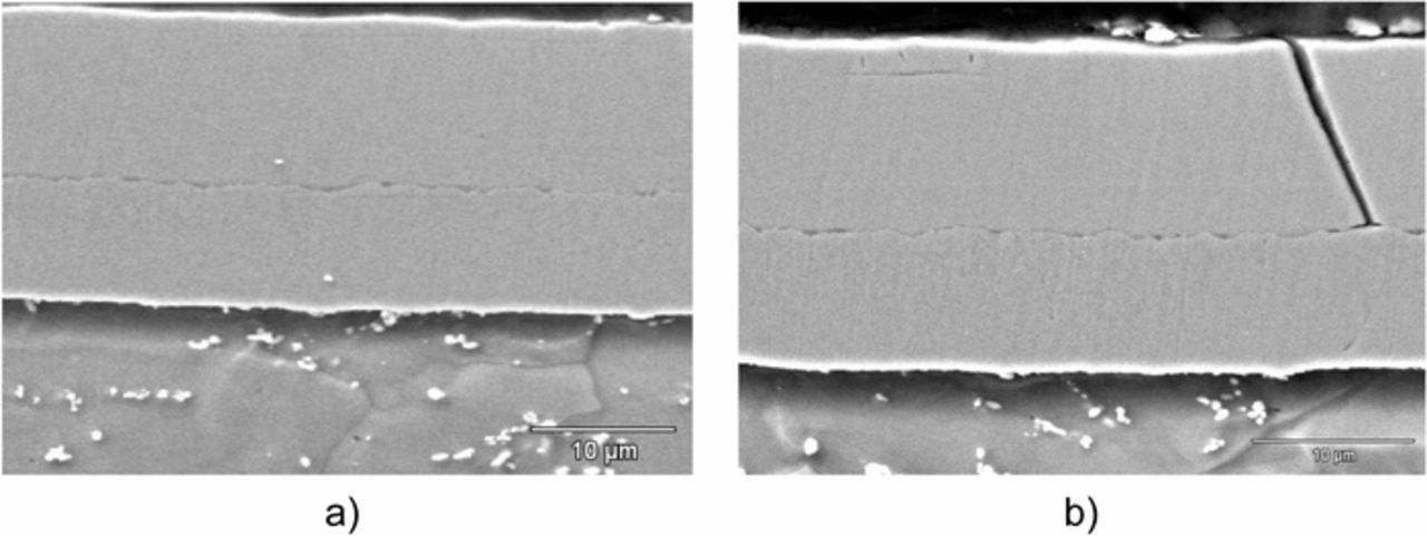
Figure 14. SEM images (3500X) of cross section of the steel/Ni(Sm)/NiB film.
Evaluation of corrosion resistance
Polarization curves obtained for the substrate and the steel/Ni(Sm)/Ni-B film are shown in Figure 15. It can be seen that the curve obtained for the bi-layer film indicates a corrosion potential of −0.50 V vs SCE, with the corresponding corrosion current density of 9.21 μA/cm2. These values are very similar to those obtained for the Ni-B coating (Ecorr = −0.532 V vs. SCE; jcorr = 10.36 μA/cm2). These parameters suggest that the bi-layer coating does not have good resistance to corrosion; on the other hand, however, the polarization curve presents a passive region (oxidation zone) similar to that which occurs with a Ni(Sm) coat. Such passive behavior is not observed for a Ni-B film, which shows an active zone due to the oxidation of the steel substrate by exposure to the aggressive medium (5% NaCl) through the micro-fissures (see Figure 3).

Figure 15. Polarization curves obtained for the substrate and steel/Ni(Sm)/Ni-B bi-layer.
The contradictory results obtained by the electrochemical technique may be resolved with additional studies. The apparent electrochemical parameters (Ecorr; jcorr) are primarily influenced by the composition of the outer layer that is in contact with the NaCl solution, in this case the Ni-B deposit, and may not reflect actual corrosion performance in service.
To complement the electrochemical tests, the films were evaluated by exposure in the salt-spray chamber. The results obtained allow one to verify that the corrosion resistance of the Ni(Sm)/Ni-B coating on steel is actually superior in comparison with the Ni-B coating (see Figure 16 and Figure 17). The bi-layer coating has a corrosion resistance longer than 1369 h in the salt spray chamber (the surface did not show red corrosion when the test was stopped at that time) while the Ni-B coating provides a corrosion resistance of only 24 h.
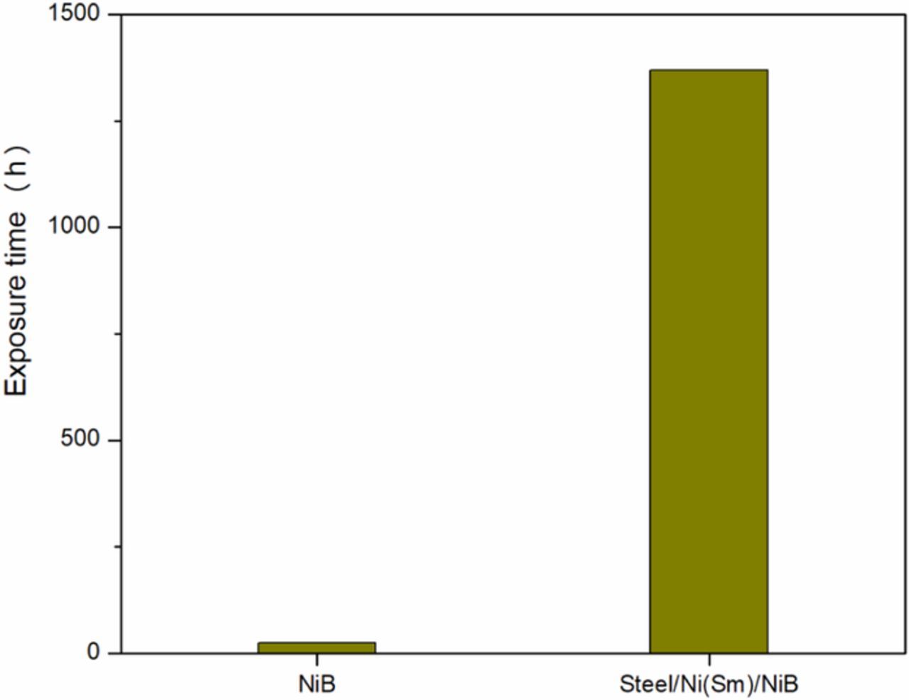
Figure 16. Results obtained by accelerated corrosion tests for steel/Ni(Sm)/Ni-B bi-layer and Ni-B films.
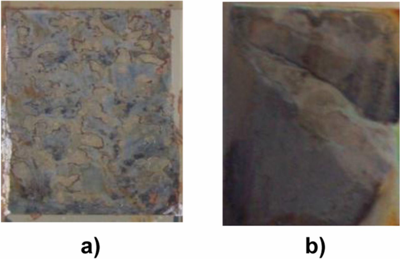
Figure 17. Photographs of samples after exposure in a salt spray chamber: a) NiB and b) steel/Ni(Sm)/NiB films.
Hardness evaluation
Results of hardness evaluation show that the overall hardness of the bi-layer film Ni(Sm)/Ni-B is 618 ± 8.7 HV, a value intermediate between the hardness values obtained for Ni-B (716 ± 22.5 HV) and Ni(Sm) (289 HV± 5.7 HV) surfaces. The overall hardness of the bi-layer is diminished due to the lower hardness of the Ni(Sm) layer. This is expected since the measurement of the hardness is carried out on the surface, and the hardness value depends on the thickness of the surface layer of the Ni-B deposit and the applied load. In this case the depth (h) of the indentation was 3.5 μm, a significant depth (29.2%) in relation to the thickness of the Ni-B layer. The overall hardness of this bi-layer could easily be increased by increasing the thickness of the NiB layer to a thickness of 20 μm.
Development of a tri-layer coating (Ni-Sm electrolytic/Ni-B/NiB-PTFE) combining the techniques of electroplating and DCP
The main objective of the preparation of a tri-layer coating is to obtain a functional film of about 20 microns which provides good resistance to corrosion, high hardness, and a low coefficient of friction. For this reason, a primary layer of electrolytic Ni(Sm) of 8 microns was made to guarantee corrosion resistance. Over this primary layer, a second Ni-B layer and a third NiB-PTFE(4.4 wt% PTFE) composite layer were prepared by DCP to provide a high hardness and low coefficient of friction. The operation details of producing these tri-layer films are summarized in Table IV.
Table IV. Identification and characteristics of the samples prepared to study their effect on hardness.
| Sample identification | Description | Estimated thickness |
|---|---|---|
| Tri-layer1 | Steel/ 8 μm Ni-Sm (electrolytic) / 2.5 μm Ni-B (DCP)/ 7.8 μm Ni-B-PTFE (4.35 wt% PTFE, DCP) | 18.3 μm |
| Tri-layer2 | Steel/ 8 μm Ni-Sm (electrolytic) / 4.2μm Ni-B (DCP)/ 3.3 μm NiB-PTFE (4.35 wt% PTFE, DCP) | 15.5 μm |
As it was previously confirmed in testing a bi-layer coating obtained by electrodeposition, the preparation of a Ni (Sm) sublayer is effective in providing good protection against corrosion. Thus, the evaluation of tri-layer coatings was focused on evaluating the hardness.
Hardness measurement
Figure 18 shows the results of hardness measurements for tri-layer coatings. The tri-layer1 and tri-layer2 films exhibited hardness values between 469 ± 62 and 564 ± 149 HV, which are in the Ni-B-PTFE hardness range. We can observe that the intermediate NiB layer thickness, which has the highest hardness, does not modify the hardness of the tri-layers. It is seen that there is a slight influence of the total thickness of the tri-layer and particularly a greater influence of the thickness of top layer of NiB-PTFE.
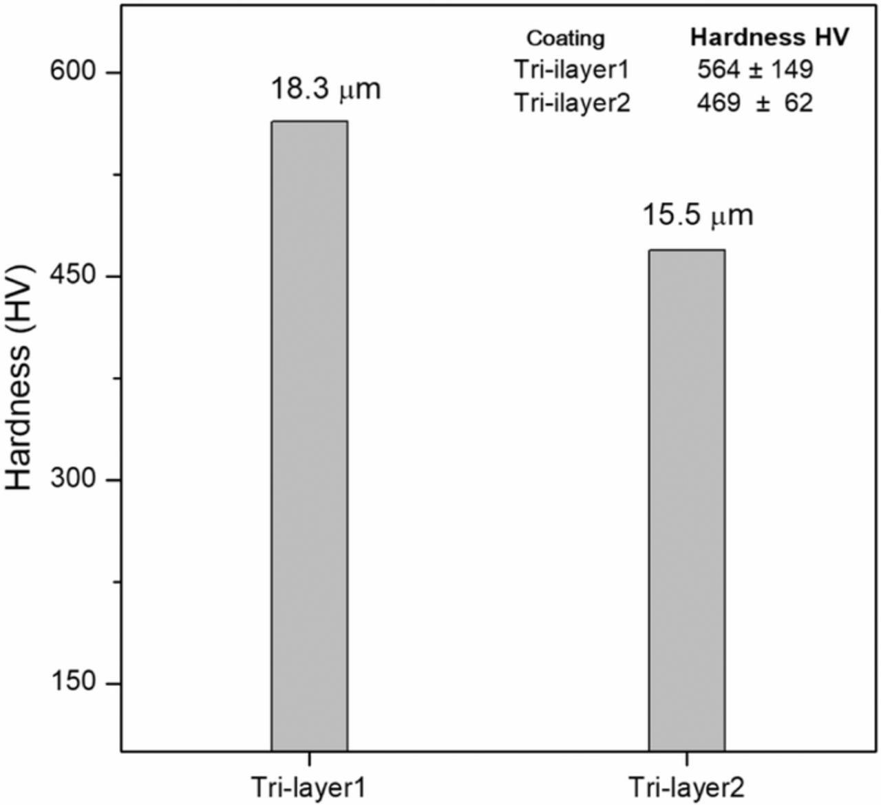
Figure 18. Hardness measurements for tri-layer coatings obtained through the combination of electrodeposition and JetMetal process.
With the purpose of facilitating industrial development of the process to obtain different specifications of the coating according to a required application, Figure 19 shows in summary form the corrosion resistance and the hardness of the studied coats. Table V summarizes the operating conditions (temperature, time, number of stages and process) for obtaining a film with the desired specifications.
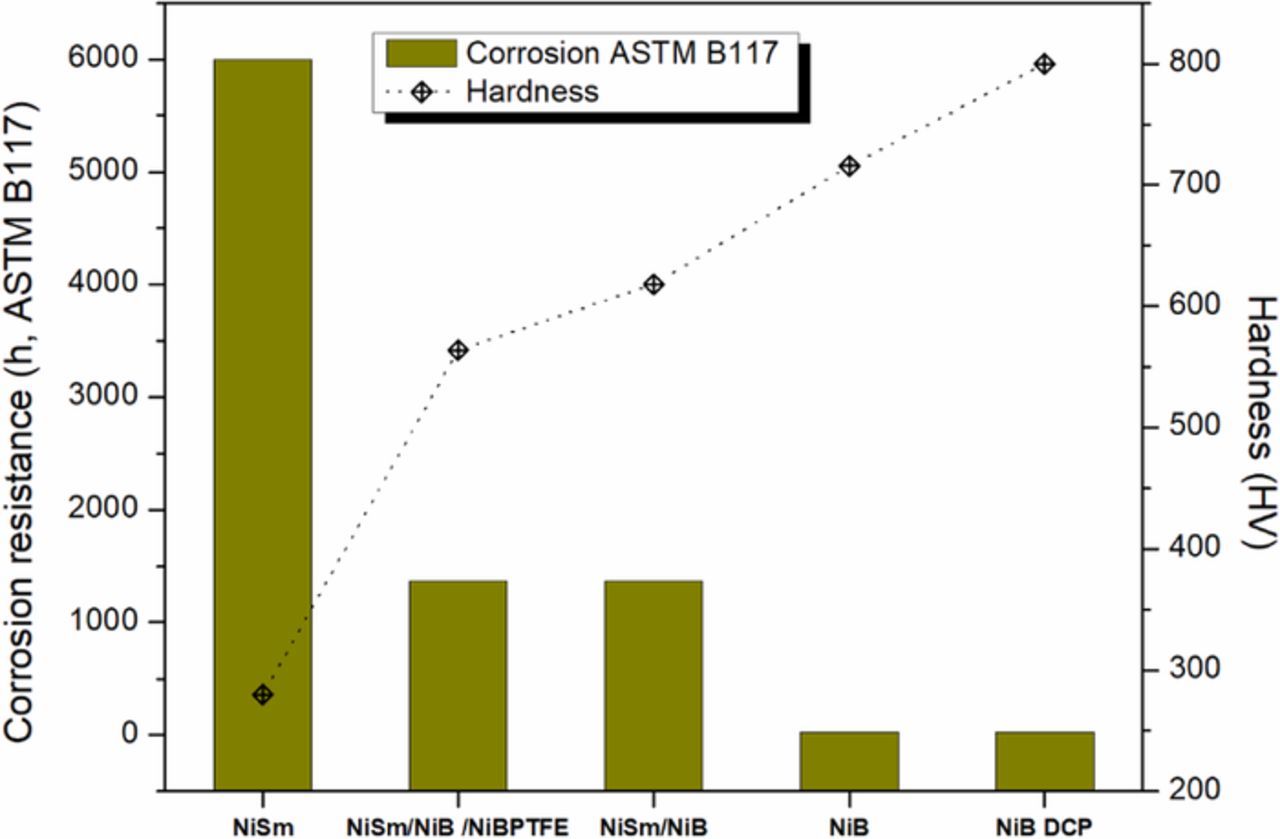
Figure 19. Hardness and resistance to corrosion, for different films obtained through the use of electroplating and dynamic chemical plating (JetMetal). The elaboration details of these coatings are shown in Table V.
Table V. Processing conditions for films shown in Figure 19.
| Processing Conditions | Ni Sm | NiSm/ NiB/ NiBPTFE | NiSm/ NiB | NiB | NiB DCP |
|---|---|---|---|---|---|
| Time | 19.5 min | 109 min | 39 min | 37min | 81 min |
| Thickness | 9 μm | 18.3μm | 22.6 μm | 23μm | 12μm |
| Temperature | 55°C | 55°C / 25°C | 55°C / 45°C | 45°C | 25°C |
| Stages | 1 | 3 | 2 | 1 | 1 |
| Process | Electroplating | Electroplating/JetMetal | Electroplating | Electroplating | JetMetal |
Conclusions
By using the electroplating technique from an electrolyte bath of Ni sulfamate with samarium, a coating can be achieved which provides excellent resistance to corrosion (more than 6000 h in CNS). This high resistance to corrosion is related to the absence of defects such as fissures in the film. Similarly, using the electroplating with an electrolytic bath containing DMAB, it was possible to obtain a Ni-B coat with high hardness (higher than 700 HV). However, this surface does not provide adequate protection against corrosion, mainly due to the presence of fissures.
Similarly, by using the dynamic chemical plating (JetMetal) technique, it was possible to obtain a Ni-B coating with a high hardness above 600 HV. However, like the Ni-B layers obtained by electroplating, these coatings are not efficient for protecting against corrosion because of the presence of defects in the NiB films.
Based on the preceding, it can be observed that the hardness and resistance to corrosion of a Ni coating are hardly compatible. In the first case, we have a high resistance to corrosion but a low hardness; in the second case we have a high hardness but low resistance to corrosion. The hardness implies strong internal interactions (high internal stress) that can cause the formation of cracks in the film, which prevents reliable protection against corrosion. A film capable of supplying excellent resistance to corrosion must be very compact and have no defects such as fissures. An intermediate layer of Ni(Sm) under NiB can introduce a barrier to retard corrosion while the outer NiB offers good surface hardness.
Finally, by combining the electroplating and DCP technique, it is possible to obtain a tri-layer coat (NiSm/ NiB/NiBPTFE) on steel that has a high resistance to corrosion of more than 1000 h in a salt-spray chamber and suitable hardness ≈ 600 HV as well as a relatively low coefficient of friction of approximately 0.4 that offers good wear resistance.
Acknowledgment
The authors thank the Mexican Council of Science and Technology (CONACYT) and the Postgraduate Program of Cooperation France-México (PCP) for their financial support of this research. J. R. Lopez and P.F. Méndez are also grateful to CONACYT for doctoral scholarships.
ORCID
J. R. López 0000-0001-5416-7875
Y. Meas 0000-0002-6494-0769