
Abstract
Zinc (Zn) is considered a promising biodegradable metal for implant applications due to its appropriate degradability and favorable osteogenesis properties. In this work, laser powder bed fusion (LPBF) additive manufacturing was employed to fabricate pure Zn with a heterogeneous microstructure and exceptional strength-ductility synergy. An optimized processing window of LPBF was established for printing Zn samples with relative densities greater than 99% using a laser power range of 80 ∼ 90 W and a scanning speed of 900 mm s−1. The Zn sample printed with a power of 80 W at a speed of 900 mm s−1 exhibited a hierarchical heterogeneous microstructure consisting of millimeter-scale molten pool boundaries, micrometer-scale bimodal grains, and nanometer-scale pre-existing dislocations, due to rapid cooling rates and significant thermal gradients formed in the molten pools. The printed sample exhibited the highest ductility of ∼12.1% among all reported LPBF-printed pure Zn to date with appreciable ultimate tensile strength (∼128.7 MPa). Such superior strength-ductility synergy can be attributed to the presence of multiple deformation mechanisms that are primarily governed by heterogeneous deformation-induced hardening resulting from the alternative arrangement of bimodal Zn grains with pre-existing dislocations. Additionally, continuous strain hardening was facilitated through the interactions between deformation twins, grains and dislocations as strain accumulated, further contributing to the superior strength-ductility synergy. These findings provide valuable insights into the deformation behavior and mechanisms underlying exceptional mechanical properties of LPBF-printed Zn and its alloys for implant applications.
Highlights
A superior strength-ductility synergy was achieved in pure zinc printed by laser powder bed fusion.
A heterogeneous microstructure with bimodal grains and dislocations was obtained.
Back-stress hardening, massive dislocations and twins are dominant in deformation.
Deformation mechanisms responsible for the strength-ductility synergy were revealed.
Export citation and abstract BibTeX RIS

Original content from this work may be used under the terms of the Creative Commons Attribution 4.0 license. Any further distribution of this work must maintain attribution to the author(s) and the title of the work, journal citation and DOI.
1. Introduction
Zinc (Zn) and its alloys have emerged as highly promising biodegradable metal materials for biomedical applications [1]. In comparison to biodegradable iron and magnesium, Zn exhibits a more moderate degradation rate without short-term hydrogen release during clinical service [2, 3]. Additionally, the released Zn ions have been demonstrated to regulate bone homeostasis and possess antibacterial properties [4–6]. Recently, Zn has been accepted as an important candidate for potential applications in cardiovascular and coronary stents, as well as orthopedic fixations [7]. Notably, the fabrication of bone implants necessitates multi-level pore structures with internal penetration to create an essential structural milieu conducive to cell proliferation, vascular ingrowth, and bone regeneration [8, 9]. However, achieving a porous structure similar to natural bone using conventional manufacturing processes for Zn (e.g. casting, powder metallurgy) poses considerable challenges [10, 11].
Laser powder bed fusion (LPBF) is a widely popular metal additive manufacturing (AM) technique that fabricates parts by selectively melting continuous thin layers of metal powders [12, 13]. It offers distinct advantages in fabricating bone implants with customized shapes and internal bionic porous structures [14, 15]. Recently, it has been utilized to prepare porous Zn implants with different pore sizes and porosities, demonstrating excellent biocompatibility and osteogenic ability [10, 16, 17]. Furthermore, LPBF involves rapid and spatially-variable heating, melting, cooling and solidification cycles of the printed material [18]. In this case, the rapid solidification process of liquid–solid phase transformation during LPBF occurs at extremely high cooling rates, typically exceeding 106 K s−1 [19]. Consequently, non-equilibrium solidification microstructures are formed under significantly large subcooling and high grain growth rates, resulting in increased solute solid solubility, much smaller grain size compared with conventionally processed counterparts, and reduced element segregation [20]. For instance, Wang et al [21] observed that the grain size of LPBF-printed pure Zn was approximately 10 μm compared to hundreds of microns for casted Zn. This finding indicates that the mechanical properties of LPBF-printed Zn significantly surpass those of conventionally manufactured counterparts (cast or extruded). Therefore, LPBF provides ample opportunities for tailoring the microstructures and mechanical properties of Zn and its alloys.
The mechanical performance of LPBF-printed Zn is determined by its printability and microstructure. In 2016, Montani et al [22] conducted the pioneering investigation into the feasibility of pure Zn prepared by LPBF and observed a relative density of only 88% due to its susceptibility to evaporation during rapid solidification caused by its low melting and boiling points, resulting in inadequate densification. Subsequently, numerous works have been dedicated to fabricating highly dense Zn samples through LPBF equipment modification [23], meticulous monitoring of the printing process [24], and optimization of process parameters to mitigate evaporation [25, 26]. For instance, Qin et al [27] achieved a relative density exceeding 99% in LPBF-printed pure Zn samples through optimizing gas protection and laser energy input. They observed that an increase in laser scanning speed led to gradual refinement of columnar grains into equiaxed grains, resulting in superior tensile strength (∼130 MPa) and ductility (∼9%) in the Zn samples printed along the build direction at the vertical plane. Similarly, Wang et al [28] and Yang et al [29] optimized LPBF process parameters for pure Zn and examined the impact of parameters on its microstructure and resultant mechanical properties. They concluded the microstructure of LPBF-printed Zn consisting of equiaxed grains and lamellar structure, demonstrating exceptional mechanical properties. In summary, the mechanical properties of LPBF-printed pure Zn are currently attributed to grain refinement strengthening, but there remains a lack of understanding regarding its deformation behaviors and relevant mechanisms, particularly with respect to quantifying its mechanical properties and their correlation to deformed microstructures.
Therefore, the present study aims to investigate the impact of process parameters on the printability, microstructure, and mechanical properties of LPBF-printed pure Zn, with a particular emphasis on its deformation behavior and relevant mechanisms to achieve enhanced mechanical strength-ductility synergy in the printed pure Zn. Highly densified Zn samples were printed without discernible metallurgical defects through the optimization of LPBF process parameters. A comprehensive examination was conducted on the microstructure of LPBF-printed pure Zn, encompassing grain features, dislocation characteristics, and texture evolution. The mechanisms governing deformation behavior and multiple strengthening were discussed to establish a correlation between microstructure and mechanical properties. These findings provide valuable theoretical references for future design and development of high-performance multivariate Zn-based materials for medical applications.
2. Methods and experiments
2.1. Material and LPBF process
Gas-atomized pure Zn powder (Shanghai Naiou Technology Co., Ltd, China) with a purity of 99.9% was utilized as the raw material for the LPBF process. The morphology of the powder is presented in figure 1(a), revealing predominantly spherical particles with smooth surfaces and indicating excellent fluidity during powder spreading. To determine the particle size distribution of Zn powder, a laser particle-size analyzer (LPSA, Microtrac S3500) was employed and an average size of 16.5 μm was obtained, as depicted in figure 1(b). Prior to the LPBF process, vacuum drying at 50 °C ∼ 60 °C for 12 h was conducted for the Zn powder.

Figure 1. Characteristics of the pure Zn powder: (a) SEM images showing the morphology of the powder (the inset is the morphology of an individual particle) and (b) particle size distribution. (c) LPBF-printed Zn samples at the horizontal plane with schematic illustrations of laser scanning strategy and geometries of tensile coupons.
Download figure:
Standard image High-resolution imageThe Zn powder was printed using a self-developed commercial LPBF machine (Dimetal-100, Laseradd, China) furnished with a fiber laser (Yb: YAG, wavelength 1 075 nm, SPI), a power of 200 W, and a focusing spot diameter of 70 μm. Table 1 presents the series of LPBF parameters (i.e. laser power, scanning speed, etc) employed to explore the processing window for Zn. The volumetric energy density E can be calculated using  , where P, V, t, and h represent the laser power, scanning speed, layer thickness, and hatching space, respectively. As depicted in figure 1(c), cubic Zn samples were prepared for characterization, while tensile samples with a gauge length of 18 mm, width of 3.2 mm, and thickness of 1.5 mm were printed for mechanical testing. The scanning track with a rotation angle of 45° and 135° between adjacent layers was applied. To prevent oxygen contamination, high-purity argon atmosphere was continuously maintained within the printing chamber. To simulate the LPBF process, powder bed model of pure Zn was established based on the discrete element method, in which the Zn powder was simplified into spheres of different sizes. The Hertz-Mindlin model was adopted in the powder laying process. Moreover, laser beam was represented by volumetric heat source distributed in Gaussian form.
Table 1. LPBF process parameters employed to fabricate Zn samples.
| Process parameters | Value |
|---|---|
| Laser power/W | 40, 60, 70, 80, 90, 100 |
| Scanning speed/(mm s−1) | 400, 600, 700, 800, 900, 1000 |
| Layer thickness/mm | 0.030 |
| Hatch space/mm | 0.055 |
2.2. Microstructural characterization
The relative density of LPBF-printed Zn samples with different volumetric energy densities was determined using the Archimedes method. The Archimedes method is particularly attractive because of its simplicity and cheapness, as well as high precision and repeatability values reported in the evaluation of standard 10 mm cube samples, especially at high relative density levels [30]. Before the test, a calibrated 200 g mass was used to calibrate the balance. Subsequently, based on ASTM B962 [31], Archimedes measurements were performed at room temperature for all cubic printed Zn samples (10 × 10 × 10 mm) with different parameters to calculate relative density. Samples were initially weighed in their desiccated state and subsequently immersed in a vacuum-sealed water environment for at least 0.5 h, ensuring the saturation of all surface-connected pores. Following that, the samples were weighed in submerged condition. The surfaces of the specimens were then desiccated with a towel, and subsequent weight measurements were conducted in their hydrated state, which means the surface-breaking pores were filled with water while the surface remained dry. To minimize testing deviations, five times were tested for each energy density.
The surface morphology of the printed samples on their horizontal planes was observed using scanning electron microscopy system (SEM, Model-FEI Nova nano 430, Netherlands). The phase compositions of the raw powder and printed Zn samples were measured via x-ray diffraction platform (Empyrean 3rd Gen, Panalytical). After etching with a 4 vol% nitric acid solution for 5 s, the microstructure along both the horizontal and vertical planes of the LPBF-printed Zn samples was characterized through a metallographic optical microscope (OM, Leica, DM4M, Germany) and SEM. Grain orientation, grain size, and texture information were analyzed through electronic backscattered diffraction (EBSD, Symmetry, Oxford Instrument Corp., UK) using AztecCrystal software. Furthermore, crystallographic structure, dislocations and lattice spacing of the LPBF-printed Zn samples were characterized by transmission electron microscopy (TEM, FEI Tecnai G2 F20, Netherlands).
2.3. Mechanical testing
Vickers microhardness (HV) experiments were conducted by a hardness tester (HXD-1000TM/LCD, China). Tensile testing was performed on a universal tester (CMT5105, SANS, China), following the ASTM E9-09 and ASTM E209-18 standards [32]. To minimize testing deviations, three samples were tested for each energy density. Subsequently, tensile facture morphologies were observed using SEM to analyze failure mechanisms. Additionally, TEM and EBSD were employed to discuss dislocation behavior, grain structure evolution, and texture variation in the fractured samples.
3. Results
3.1. Printability
The printability of pure Zn via LPBF under different volumetric energy densities is presented in figure 2. Figure 2(a) illustrates the calculated distribution of energy densities for various laser powers (40 ∼ 100 W) and scanning speeds (400 ∼ 1000 mm s−1). Specifically, the determined intervals for energy density mainly include 0 ∼ 30 J mm−3, 30 ∼ 50 J mm−3, 50 ∼ 80 J mm−3, and above 80 J mm−3. Subsequently, a graph depicting the relationship between the energy density and relative density of the printed Zn is plotted in figure 2(b). Notably, higher laser powers generally resulted in superior relative densities in printed Zn within an energy density range of 0 ∼ 50 J mm−3. Furthermore, a significant improvement in relative density was achieved when transitioning from an energy density of 50 –80 J mm−3. However, it should be emphasized that a noticeable deterioration occurred when improving the energy density from 80 J mm−3 to 160 J mm−3. Consequently, it can be concluded that LPBF-printed pure Zn demonstrated optimal relative density within the energy density range of 50 ∼ 80 J mm−3.

Figure 2. Preliminary process parameters employed to fabricate pure Zn via LPBF: (a) processing window and (b) relationship between relative density and volumetric energy density under various laser powers. SEM images showing the surface morphology of representative Zn samples printed with different energy densities: (c) before polishing and (d) after polishing.
Download figure:
Standard image High-resolution imageFurthermore, the effect of energy density on the surface quality of LPBF-printed Zn samples along their horizontal planes is illustrated in figures 2(c) and (d). When the energy density was below 30 J mm−3, an abundance of unmelted Zn powder particles, porosities, and sintering necks were evident on sample surfaces because of insufficient energy input. After polishing, a significant amount of incompletely melted particles were also found in irregular pores, which hindered metallurgical bonding between adjacent solidified molten tracks and consequently deteriorated sample fabrication. It is widely acknowledged that higher energy densities can elevate the temperature within a molten pool [33]. The increasing temperature led to accelerated migration of Marangoni flow from the center of Zn molten pool towards its edge, thus facilitating bonding between adjacent molten tracks. Therefore, when the energy density ranged from 30 J mm−3 to 50 J mm−3, the width of molten track gradually increased and adjacent tracks tended to coalesce, while ensuring a steady and continuous molten track with minimal presence of unmelted particles and porosities. Upon reaching an optimal value range (50 ∼ 80 J mm−3), uniformly formed molten tracks appeared on sample surfaces. Additionally, no significant porosities were observed, indicating excellent metallurgical bonding between adjacent tracks and resulting in relatively higher surface quality attainment. However, further increase in the energy density (>80 J mm−3) intensified the evaporation of Zn particles due to high energy density levels that subsequently increased recoil pressure within the molten pool. Consequently, several spherical particles formed as a result of the balling phenomenon, thus compromising printing quality. OM images along the vertical planes with different energy densities are shown in figure S1, showing a similar trend to figures 2(c) and (d).
Based on the aforementioned analysis, the appropriate energy density should be confined within a narrow range of 50 ∼ 80 J mm−3 (red area in figure 2(b)). However, it is noteworthy that when employing the identical energy density but different combinations of power and speed values to print Zn samples, significant variations in relative density were observed (yellow area in figure 2(b)). Therefore, further process parameter optimization was conducted to explore the precise optimal conditions for printing Zn. Specifically, a laser power range of 70 ∼ 90 W and scanning speed range of 700 ∼ 1000 mm s−1 were further applied. The horizontal surfaces of the printed Zn samples are depicted in figure 3(a). Based on the defect morphology, the processing parameter map could be categorized into unfused, densified, keyhole, and transition zones. At relatively lower power and higher speed (corresponding to low energy density values marked with yellow boxes), numerous unfused cracks and pores manifested on the surface. Some incompletely melted powder particles even became entrapped within these unfused defects. In contrast, gas pores and keyholes were observed on the Zn samples fabricated at relatively higher power and lower speed (corresponding to high energy density values marked with blue boxes). Only a few defects were observed on the Zn samples prepared using a power range of 80 ∼ 90 W and a speed range of 800 ∼ 900 mm s−1.

Figure 3. Further process optimization for printing Zn via LPBF: (a) typical defects observed in printed Zn samples under different combinations of power and speed; (b) relative density and (c) microhardness corresponding to various processing parameters.
Download figure:
Standard image High-resolution imageThe relative densities of the LPBF-printed Zn samples corresponding to different processing parameters are presented in figure 3(b). Similarly, it was observed that Zn samples printed at both low and high energy densities exhibited poor relative densities because of the significant internal defects (figure 3(a)). However, compared with gas pores, the unfused defects had a more pronounced impact on the relative density. The highest relative density of 99.86% was achieved when applying the laser power of 80 W and scanning speed of 900 mm·s−1. In addition, lower relative densities resulted in more discrete distribution in microhardness from different areas (figure 3(c)). The printed Zn with the highest relative density exhibited a remarkably high average hardness value of 53 HV, which could be attributed to its high surface quality. In summary, the optimal values of laser power and scanning speed were determined.
3.2. Microstructure
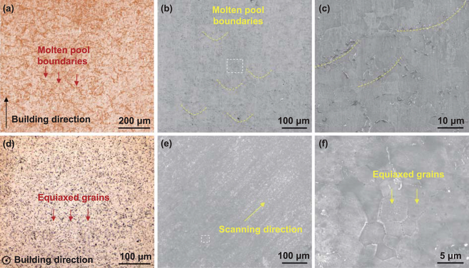
The microstructure of the LPBF-printed pure Zn in both vertical and horizontal planes is presented in figure 4. Semi-elliptical shaped molten pools and equiaxed grains could be observed as exhibited in figures 4(a) and (d), respectively. The SEM results for the vertical and horizontal planes are displayed in figures 4(b)–(f), respectively. Figures 4(b) and (e) depict low magnifications images revealing the extensive presence of molten pools and fusion tracks. Notably, a substantial number of equiaxed grains and lamellar structure were found with lamellae growing perpendicular to the molten pool boundary on the vertical plane (figure 4(c)), which was consistent with previous findings by Wang et al [28]. Additionally, an enlarged view of the horizontal plane (figure 4(f)) vividly demonstrated a well-ordered arrangement of numerous highly equiaxed grains that exhibited smaller sizes compared to those observed in the vertical plane.

Figure 4. Microstructure of the LPBF-printed Zn samples along different planes: (a) OM image and (b), (c) SEM images along the vertical plane; (d) OM image and (e), (f) SEM images along the horizontal plane.
Download figure:
Standard image High-resolution imageThe grain growth and crystallographic orientation of the printed Zn sample with the highest density using the optimal parameters (i.e. P = 80 W, V = 900 mm s−1) were investigated through EBSD characterization, and the results are presented in figure 5. As presented in figure 5(a), most grains exhibited a columnar morphology with their long axis aligned parallel to the building direction (BD), and some reaching heights of hundreds of micrometers. A majority of grains displayed preferred orientations along <0001> (red region) parallel to the BD. On the vertical plane, the LPBF-printed Zn sample demonstrated a strong <0001> partial fiber texture with a maximum intensity of multiples of uniform density (MUD) reaching 15.91 (figure 5(c)). In contrast, on the horizontal plane (figure 5(b)), a bimodal grain structure consisting of alternately coarse grains and fine grains was observed. Most grains exhibited preferred orientations along <−12−10> (green region) and <01−10> (blue region) perpendicular to the BD on this plane. Notably, the average grain size on the horizontal plane was smaller than that on the vertical plane, which was consistent with the results as shown in figure 4. Furthermore, while the <0001> fiber texture became diffused and weakened, the <10−10> texture exhibited significantly enhanced strength. As illustrated in figure 5(d), the texture intensity measured for the printed Zn sample on the horizontal plane reached up to 6.08 MUD. It is generally accepted that grain refinement can weaken the texture strength [34]. Therefore, the texture intensity on the horizontal plane was smaller than that on the vertical plane (15.91 MUD). It has been reported that the weakening of texture has a positive effect on the enhancement of mechanical strength [35].

Figure 5. EBSD characterization of the LPBF-printed Zn samples along different planes: (a), (b) IPF maps along vertical and horizontal planes, respectively; and (c), (d) PFs maps along vertical and horizontal planes, respectively.
Download figure:
Standard image High-resolution imageThe bimodal grain structure of the LPBF-printed pure Zn was revealed through high-magnification EBSD as depicted in figure 6. It is evident that Zn grains exhibited an irregular wave morphology along the molten pools instead of the conventional plane morphology. The coarse-grain region and fine-grain region could be observed, in which the grains at the boundary of the molten pools were much smaller than those at the center of the molten pools. The band contrast map overlaid with low-angle grain boundaries (LAGBs) and high-angle grain boundaries (HAGBs) is presented in figure 6(a), where red and blue lines represent LAGBs (2° ∼ 15°), specifically highlighting sub-grain boundaries denoted by red lines; while black line corresponded to HAGBs (>15°). The results indicated a significant presence of LAGBs within the grains, predominantly clustered at the boundary of the molten pools. Moreover, kernel average misorientation (KAM) analysis (figure 6(b)) revealed a high density of dislocations inside these grains due to rapid cooling and solidification. Notably, the estimate of dislocation density by the KAM map is smaller than the actual value, because it only considers geometrically necessary dislocations (GNDs) [36]. More importantly, dislocation density in the fine-grain region surpassed that in the coarse-grain region, suggesting different mechanical properties associated with the bimodal grain structure [37]. Furthermore, figures 6(c) and (d) illustrate the grain size distribution for both regions, indicating average grain sizes of (5.76 ± 1.62) µm for the fine-grain region and (36.27 ± 5.98) µm for the coarse-grain region.

Figure 6. Bimodal grain morphology of the LPBF-printed Zn samples at high magnification through EBSD analysis: (a) band contrast map with superimposed LAGBs and HAGBs; (b) KAM color map; and (c), (d) the grain size distribution in the fine-grain and coarse-grain region, respectively, as obtained from figure 5(b).
Download figure:
Standard image High-resolution imageTEM was utilized to analyze the detailed microstructural features of the LPBF-printed Zn sample with optimal parameters (i.e. P = 80 W, V = 900 mm s−1), as depicted in figures 7(a)–(c). Remarkable dislocation pileups were observed on the Zn matrix, indicating a substantial increase in local stress after solidification of the LPBF process. In addition, high-resolution TEM imaging identified several dislocation lines with stacking faults, accompanied by numerous crystal lattice distortions evident in the fast Fourier transformation (FFT) image. As presented in figure S2, it is evident that the main diffraction peak (101) of α-Zn displayed a slight shift from a low angle (43.09°) to a higher angle (43.25°), indicating a decrease in the lattice constant of the Zn sample due to the crystal lattice distortions. The pronounced lattice distortion was attributed to pre-existing dislocation accumulation that coincided with the KAM map (figure 6(b)). These pre-existing dislocations were deemed to make a significant contribution to exceptional mechanical strength and ductility exhibited by the printed Zn.

Figure 7. TEM analysis on the LPBF-printed Zn sample with optimal parameters (i.e. P = 80 W, V = 900 mm·s−1): (a) bright-field image of dislocation pileups in pure Zn; (b) an enlarged view in figure 7(a) to show the sharp dislocations morphology; and (c) FFT image exhibiting the lattice distortion.
Download figure:
Standard image High-resolution image3.3. Mechanical properties and deformation behavior
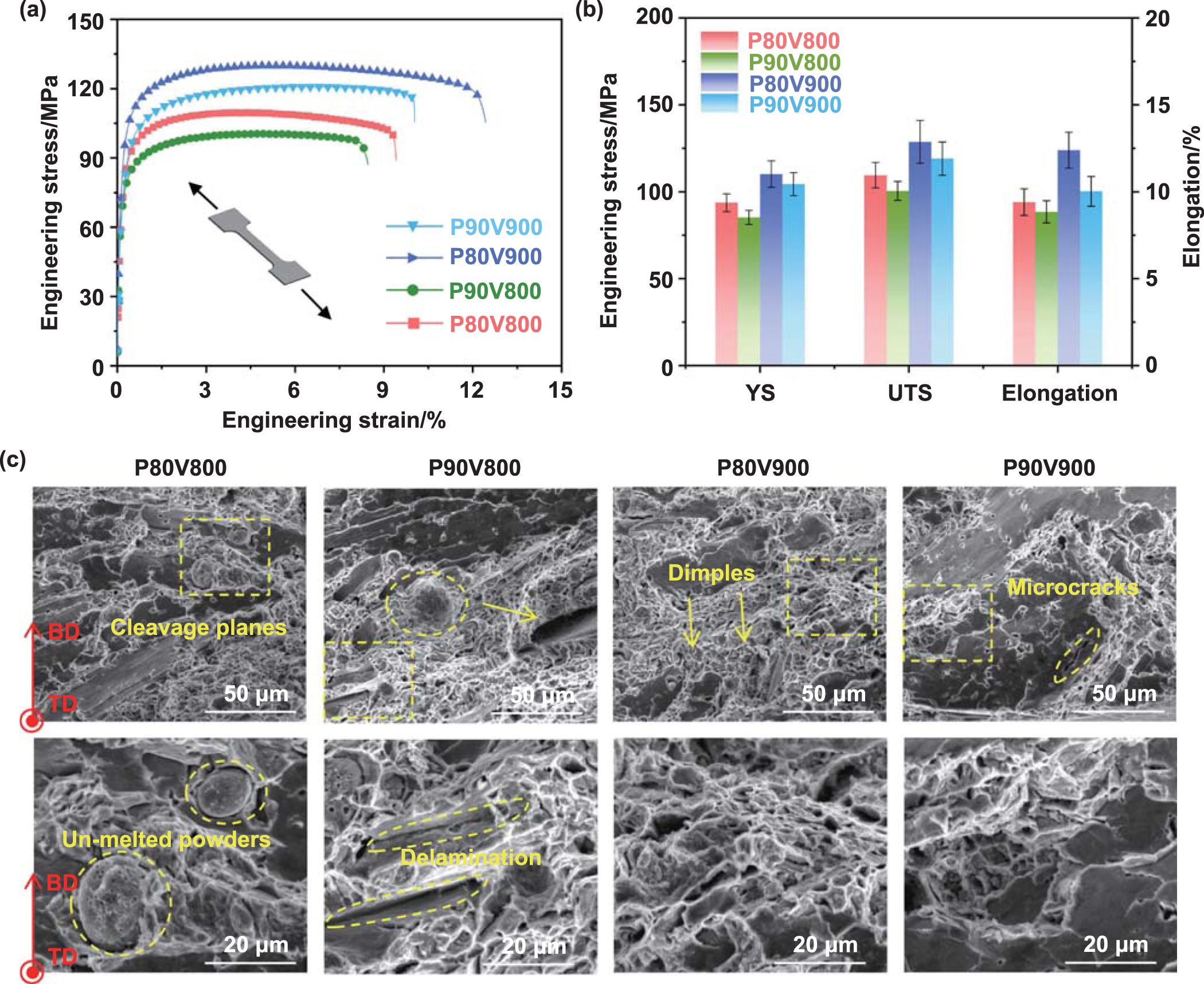
To investigate the correlation between mechanical properties and process parameters, tensile testing was conducted on LPBF-printed Zn samples at the horizontal plane at room temperature. The representative stress-strain responses under various process parameters are depicted in figure 8(a), while the yield strength (YS), ultimate tensile strength (UTS), and elongation values are presented in figure 8(b). It is evident that, for a constant laser power, the UTS gradually increased with an increase in the speed from 800 mm s−1 to 900 mm s−1. Conversely, for a constant scanning speed, the UTS gradually decreased as the power improved from 80 W to 90 W. Consequently, by determining the power of 80 W and speed of 900 mm s−1, an optimal combination of mechanical strength and elongation was achieved for LPBF-printed Zn with relatively high values of UTS (128.7 MPa), YS (110.23 MPa), and elongation (12.1%).
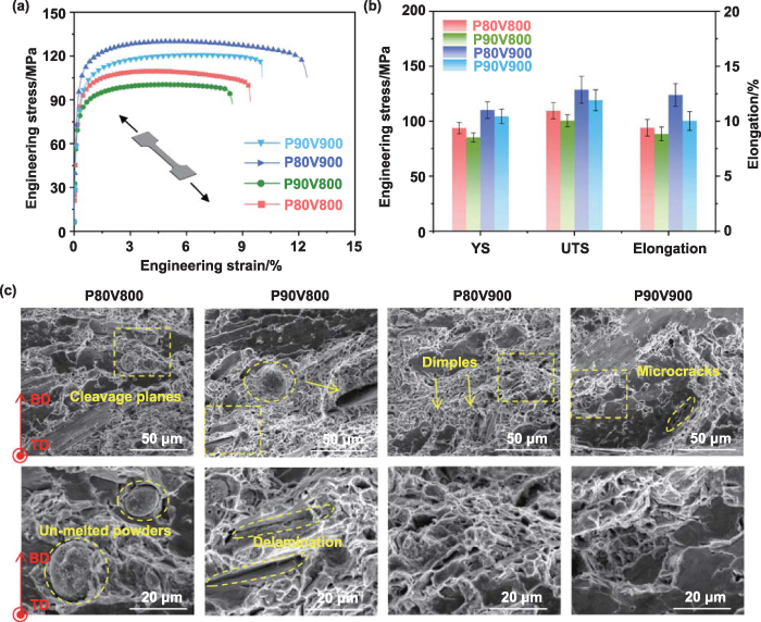
Figure 8. Tensile properties of Zn samples printed at the horizontal plane under representative process parameters: (a) stress–strain responses and (b) calculated values of UTS, YS and elongation. (c) SEM images showing the morphology of fracture surface after tensile testing.
Download figure:
Standard image High-resolution imageThe fracture of the printed Zn samples was analyzed by examining the morphology of fractured surfaces, as shown in figure 8(c). At a power of 80 W and a speed of 800 mm s−1, distinct cleavage planes, dimples, and unmelted powder particles were observed. The presence of these unmelted particles had an adverse impact on the tensile properties [38]. Unfortunately, when the laser power was increased to 90 W, gas pores and deep cracks were also detected along with cleavage planes and dimples. Under optimal parameters (i.e. P = 80 W, V = 900 mm s−1), significant changes occurred in the morphologies with numerous equiaxed dimples accompanied by small cleavage planes being exhibited. This phenomenon indicated that it belonged to a ductile-brittle mixed fracture mode which was consistent with its relatively higher ductility and strength. However, further augmenting the power to 90 W resulted in the appearance of numerous large cleavage planes and microcracks that could compromise mechanical properties.
To elucidate the correlation between unique microstructure (i.e. bimodal grain structure and pre-existing dislocations) and exceptional mechanical properties, a systematic analysis was conducted on the microstructural variation of the LPBF-printed Zn before and after tensile deformation. It is evident that the orientation, morphology and texture strength of Zn grains underwent significant changes after tension (figures 9(a)–(c)). Prior to the tensile testing, most grains exhibited preferred orientations along <−12−10> and <01−10> (figure 5(b)). However, following the tensile deformation, a majority of grains rotated and displayed a strong <0001> orientation with a textural strength of 7.62 MUD (figures 9(b)–(c)). Additionally, it should be noted that the coarse-grain regions experienced substantial elongation along the deformation direction after tension, while the fine-grain regions maintained almost unchanged morphology. According to the Hall–Petch phenomenon [39, 40], it can be inferred that the fine-grained regions exhibited greater hardness compared to the coarse-grained regions. Therefore, severe plastic deformation tended to occur in softer coarse-grain regions, whereas weaker deformations were observed in the fine-grain regions because of their higher strength.

Figure 9. EBSD characterization on the fracture of the LPBF-printed Zn samples after tension: (a) band contrast (BC) maps of Zn close to the tensile fracture; (b) IPF maps; (c) PF maps; (d)–(f) the distribution and statistics of grain boundary misorientation angles before and after tensile testing; and (g)–(i) the images and statistics of KAM before and after tensile testing.
Download figure:
Standard image High-resolution imageThe grain boundary misorientation angles and detailed statistical results of the LPBF-printed Zn sample before and after tensile testing are presented in figures 9(d)–(f). It is observed that the proportion of LAGBs was 64.3%, which increased to 77.9% after the tensile testing. This increase could be attributed to the rotation and deformation of Zn grains during tension, resulting in a significant formation of LAGBs through dislocation aggregation. KAM maps were utilized to characterize the local lattice strain levels within the Zn grains (figures 9(g)–(i)). The enhanced presence of LAGBs led to an increase in local misorientation, as evidenced from the KAM diagram. Specifically, the fractured Zn sample exhibited a much higher value (1.05°) compared to the counterpart before tensile testing (0.78°). A higher KAM value indicated greater stored strain energy, implying a high dislocation density. This facilitated further accumulation of dislocations during tensile deformation and activated additional dislocation slip, thereby improving the mechanical behavior of LPBF-printed Zn.
4. Discussion
4.1. Formation mechanism of heterogeneous microstructure via LPBF
The microstructure of LPBF-printed Zn exhibited significant differences compared to traditionally manufactured counterparts. The LPBF-printed Zn had significantly finer grains than cast Zn (10.54 µm versus 600 µm [41]). Notably, the average grain size of the printed Zn was even smaller than that of extruded and hot-rolled Zn (20 µm [42] and 40 µm [43], respectively). Of particular importance is the formation of a bimodal grain structure consisting of equiaxed-columnar grains on the horizontal plane (figure 6). Along each molten pool boundary, fine nearly equiaxed grains with an average size below 6 μm were distributed, while coarse nearly columnar grains with an average size exceeding 35 μm grew from the molten pool boundaries toward their centers.
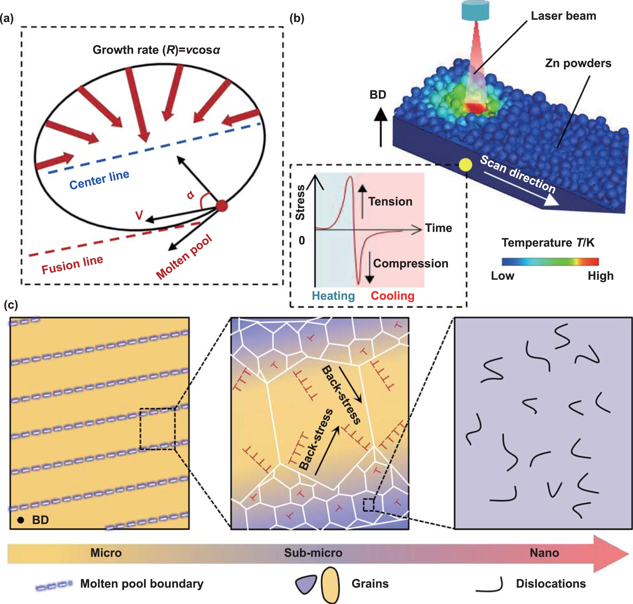
The generation of the bimodal grain structure is ascribed by the rapid cooling rate (up to 106 K s−1) and significant thermal gradient experienced during the LPBF process. The undercooling of Zn liquid phase in the molten pool is highly variable because of the Gaussian distribution of laser energy, which consequently affects both temperature gradient and solidification rate, thus influencing Zn grain growth. As depicted in figure 10(a), the growth rate R of Zn grains could be defined as [44]:


Figure 10. Schematic illustration of the formation mechanism of unique microstructure in the LPBF-printed pure Zn: (a) variation in growth rate along molten pool boundaries; (b) LPBF process for pure Zn including a sketch of stretch-compression cycles induced by laser scanning during the fast heating and cooling process; and (c) heterogeneous microstructures at micro, sub-micro and nano scales.
Download figure:
Standard image High-resolution imagewhere v represents the scanning speed, and α denotes the angle between the scanning direction and the direction normal to the molten pool. According to equation (1), the α values at center line and fusion line are determined as 0° and 90°, respectively. Consequently, the R value can reach its maximum at the center line while being minimized to 0 at the fusion line. Additionally, it is widely acknowledged that the temperature gradient experienced by the laser on the fusion line surpasses that on the center line, leading to significant subcooling and promoting heterogeneous nucleation [45]. Therefore, highly unconventional features with the bimodal grain structure are formed in the pure Zn printed by LPBF.
The schematic of the LPBF process for printing pure Zn is illustrated in figure 10(b), depicting the stress state experienced by the printed Zn. The rapid layer-by-layer melting and solidification result in a specific thermal history for the printed Zn within a short duration. This thermal history during the LPBF process is of vital importance in driving the formation of pre-existing dislocations (figure 7). According to classic solidification theory, these pre-existing dislocations can be formed because of highly periodic thermal stresses triggered by fast heating and cooling processes [46, 47]. The resulting thermal contraction stress generates strains, promoting sub-grain formation. As a result, numerous GNDs are induced to relieve stress-energy caused by low orientation differences between neighboring sub-grains, leading to gradual accumulation and even in-situ dislocation formation. Meanwhile, during the repetitive and nonequilibrium scanning process, laser scanning induces corresponding stretch-compression cycles due to significant thermal gradients, resulting in accumulation and generation of the pre-existing dislocations that usually exhibit excellent thermal stability [48]. A series of schematic diagrams depict the morphologies of the horizontal plane in the printed Zn at various scales, including millimeter-scale molten pool boundaries, micrometer-scale bimodal grains, and nanometer-scale pre-existing dislocations (figure 10(c)). It should be noted that the schematic diagram only considers a single scanning track without accounting for the repeated heating and partial remelting of the adjacent melt boundary tracks. In summary, the distinctive manufacturing characteristics of LPBF result in a periodic heterogeneous microstructure in pure Zn.
4.2. Deformation mechanisms of LPBF-printed pure Zn material
To investigate the deformation mechanism of the printed Zn, a comprehensive analysis is conducted on the deformed microstructure of LPBF-printed Zn. It is observed that the plastic deformation of the coarse-grain regions is constrained by their surrounding fine-grain regions, resulting in a lack of compatibility in deformation between them. Consequently, abundant GNDs form near the boundaries to accommodate the tensile deformation. These GNDs, originating from the bimodal grain structure, are widely recognized for their ability to enhance back stress hardening and contribute to exceptional work-hardening capability [49]. To elucidate this remarkable strain hardening ability exhibited by the LPBF-printed Zn, the density of GNDs across bimodal grain boundaries after tension is characterized and estimated as shown in figure 11. Several adjacent grains representing the bimodal grain structure are selected from the EBSD orientation maps as indicated by blue arrows in figures 11(a) and (d). The corresponding maps and calculated distribution of GNDs along the arrow direction are described in figures 11(b)–(f). Notably, the GNDs density ( ) can be calculated using strain gradient theory as follows [50]:


Figure 11. Evolution of GNDs across bimodal grain boundaries in the printed Zn sample after fracturing: (a), (d) enlarged EBSD orientation maps; (b), (e) GNDs maps; and (c), (f) equivalent position curves of GNDs density.
Download figure:
Standard image High-resolution imagewhere ϑ, μ and b are the value of KAM, the step size in the EBSD test, and Burgers vector of Zn (0.2664 nm) [51], respectively. The results demonstrate the presence of regions with high GNDs density near the boundaries of the coarse grains and fine grains. Consequently, under tensile deformation, the bimodal Zn grains can produce a large number of GNDs and exhibit exceptional back-stress hardening. This phenomenon should be more precisely defined as heterogeneous deformation-induced hardening [52]. It signifies that the LPBF-printed Zn possesses excellent strain-hardening capability, thereby achieving a balance between mechanical strength and ductility. The introduction of a bimodal grain-size distribution has proven to be an effective strategy in fabricating metallic materials with enhanced strength and ductility. The presence of fine grains contributes to increased strength, while the inclusion of coarse grains facilitates strain hardening, thereby promoting satisfactory ductility [53]. For example, Li et al [39] have found that Cu-15Ni-8Sn alloy with a bimodal grain structure could significantly increase plasticity while retaining high strength.
More importantly, a lamellar structure with a thickness of approximately 5 μm is observed (indicated by red lines) in the Zn sample undergoing tensile fracture. This structure exhibits a characteristic misorientation of <10−12> tensile twin, as illustrated in figure 12(a). The analysis of deformation twins is further presented in figures 12(b)–(f). Notably, twin lamellae with distinct orientations intersect to form intricate twin networks (figure 12(b)). The corresponding inverse pole figure confirms that the texture shifts towards the <0001> direction (figure 12(c)). Interestingly, most of the deformation twins occur within the coarse-grain regions, while only a few are found within the fine-grain regions (figure 12(d)). This phenomenon suggests that the bimodal grain structure significantly influences twinning behavior; specifically, the fine-grain regions can increase the critical twinning stress during tensile deformation and thus impede twinning occurrence. Two lines spanning multiple twins are selected for measuring misorientation profiles as depicted in figures 12(e)–(f). The results reveal that the deformation twins rotate by 80° ∼ 90° relative to the Zn matrix.

Figure 12. Characterization of deformation twins in the printed Zn sample after fracturing: (a) BC maps with deformation twins; (b) enlarged IPF map of the yellow boxed area in (a), where only deformation twins are extracted; (c) corresponding PF map; (d) corresponding BC map; and (e), (f) misorientation profiles along Line 1 and Line 2.
Download figure:
Standard image High-resolution imageTherefore, it can be concluded that the printed Zn undergoes extensive lattice rotation accompanied by deformation twinning during the tensile process. The c/a ratio of the Zn lattice (1.856) is higher than that of ideal hexagonal crystal (1.732), rendering it highly susceptible to twinning behavior. The complex interplay between deformation twins, grain boundaries, and dislocations improves the work hardening capability of the printed Zn. Generally, discontinuous plastic deformation near grain boundaries easily leads to localized dislocation pileups. Fortunately, as tensile strain increases, the formation of deformation twins effectively alleviates local stress concentration and prevents premature cracking. As a result, its mechanical strength is enhanced due to increased dislocation capacity. Twinning-induced plasticity (TWIP) effect is well-established [54]. Therefore, these deformation twins in pure Zn act as strong barriers impeding dislocation motion and contribute to excellent work-hardening capacity while improving ductility.
The dislocation evolution in LPBF-printed Zn under tensile deformation with different strains ( ) is illustrated in figure 13, where free dislocations, dislocation lines, and dislocation walls are marked by red, green and yellow lines, respectively. At the initiation of the tensile process ( = 2%), several free dislocations are observed, which gradually align to form discontinuous dislocation lines (figures 13(a) and (d)). As the strain increases up to 10% (figures 13(b) and (e)), a significant multiplication of dislocations occurs with individual long dislocation arrays activated at the boundaries, leading to periodic arrangement along tilted boundaries as discontinuous walls. Following tensile fracture, it can be observed that the grain boundaries exhibit well-organized continuous dislocation walls (figures 13(c) and (f)), while free dislocations and dislocation lines are distributed within the grains. It is widely acknowledged that reducing stored energy in materials necessitates the rearrangement of dislocations through processes such as sliding, climbing, and cross-sliding [55, 56]. Typically, the formation of dislocation walls is attributed to the accumulation of dislocations with the identical Burger's vector. The presence of the LAGBs results from continuous influx of dislocation into existing walls during the deformation process, which aligns with the findings presented in figure 9(d).

Figure 13. Evolution of dislocation patterns in LPBF-printed Zn sample at different tensile strains: (a), (d) 2%; (b), (e) 10%; and (c), (f) 12.1% (fracture).
Download figure:
Standard image High-resolution image4.3. Strengthening mechanisms
In this study, the LPBF-printed Zn achieves superior ductility and high tensile strength compared with the counterparts prepared by conventional processes such as casting [41, 57–61], hot extrusion [42, 62–67], and hot rolling [43, 62] (figure 14(a)). Among all reported LPBF-printed Zn samples to date [21, 23, 27, 29, 68–78], the printed Zn at the horizontal plane demonstrates the highest mechanical properties with a UTS of 128.7 MPa and a ductility of 12.1%, enabling it as a promising candidate for designing Zn-based implant in biomedical applications. It is worth noting that LPBF-printed Zn generally displays significant mechanical anisotropy. For instance, Qin et al [27] found the LPBF-printed Zn samples exhibited higher strength (∼130 MPa) at the vertical plane compared to the counterparts at the horizontal plane (∼90 MPa). Similarly, Wen et al [79] obtained the highest UTS (∼135 MPa) and elongation (∼11%) in the LPBF-printed Zn samples at the vertical plane. Therefore, our printed Zn samples at the horizontal plane in this study demonstrate the superior ductility along with comparable UTS even compared to all previously reported printed Zn material at the vertical plane.

Figure 14. Strengthening mechanisms of the LPBF-printed Zn: (a) comparison of the mechanical properties between LPBF-printed Zn in this study and other counterparts; (b), (c) Taylor factor map of Zn before the tensile testing and corresponding detailed distribution graph of Taylor factor value, respectively; (d) calculated and experimental YS contributions; and (e) schematic diagram of the plastic deformation process in pure Zn.
Download figure:
Standard image High-resolution image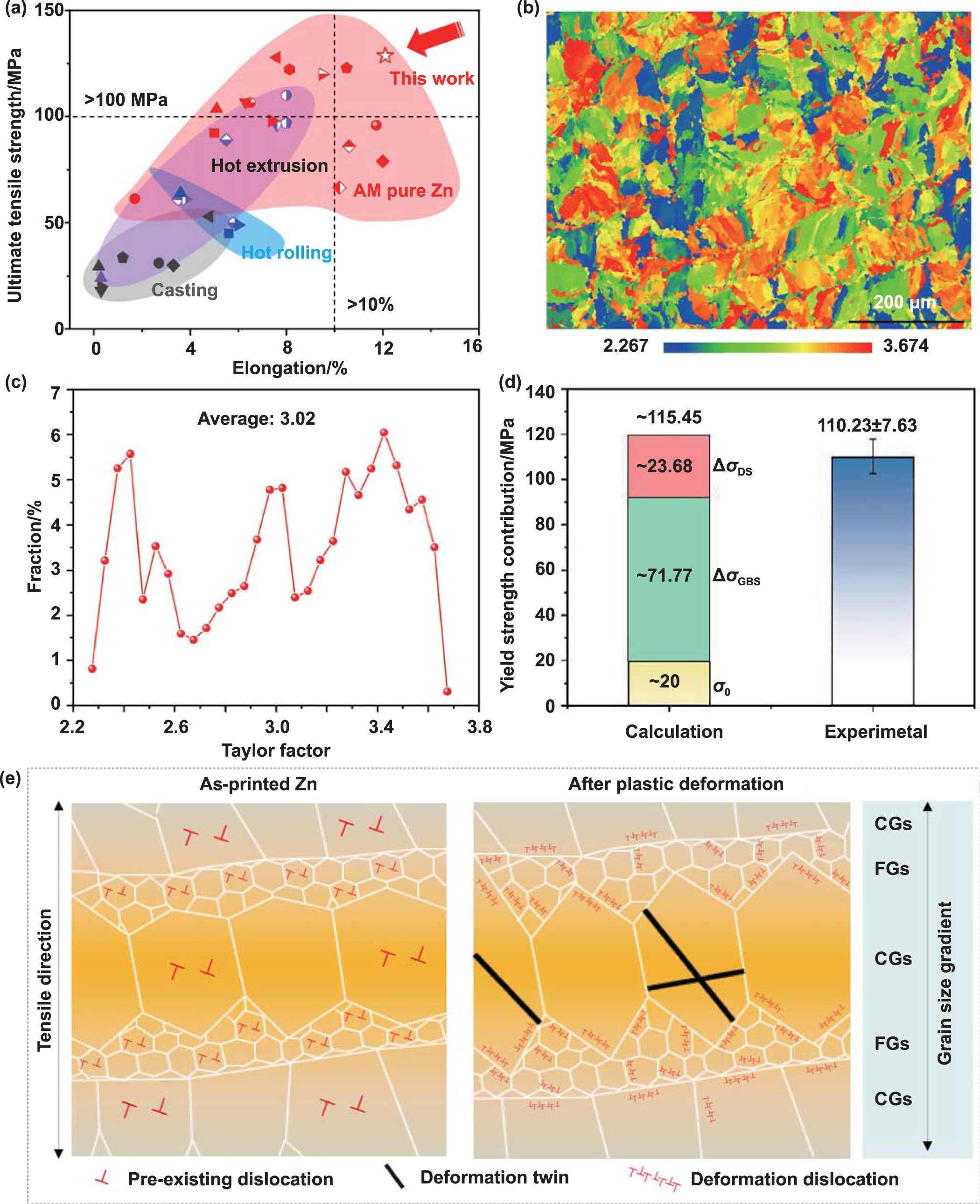
The excellent YS to resist plastic deformation is due to a combination of dual strengthening mechanisms in the heterogeneous microstructure, characterized by bimodal grain structure and pre-existing dislocations. Therefore, the theoretical  YS of Zn can be expressed by:

where  0 denotes the lattice friction stress (20 MPa for Zn alloy [51]),
  GBS represents the grain boundary strengthening (GBS), and
  DS is the dislocation strengthening (DS).
The fast cooling rate of laser melting processes effectively suppressed grain growth, resulting in a significant increase in grain size by several orders of magnitude compared to conventional cast Zn. Meanwhile, the observed bimodal grain structure facilitates further exploration of the GBS phenomenon. By applying the Hall-Petch relationship,  GBS can be calculated as [77]:

where K represents the strengthening coefficient (220 MPa µm1/2 for Zn alloy [80]), and d denotes the average grain size. Generally, the d value is determined by calculating the average circular diameter in a material with homogeneously distributed equiaxed grains. However, as depicted in figure 6, the LPBF-printed Zn samples exhibited a bimodal grain structure consisting of both coarse-grain and fine-grain region. To consider the combined effect of different grain regions, the effective grain size (dx ) can be calculated using the rule-of-mixtures for these two types of grains, as described by [81]:
where Vf, Vc, df and dc represent the volume fractions, the effective grain size of fine-grain region and coarse-grain region, respectively. The df and dc were measured to be 5.76 µm and 36.27 µm, respectively. Therefore, the estimated dx value is determined to be 9.39 µm. Based on equation (4), the predicted GBS contributions from the coarse-grain regions and fine-grain regions amount to 71.77 MPa.
Plastic deformation in most crystalline materials highly depends on dislocation strengthening, which primarily arises from interactions between pre-existing and mobile dislocations during plastic deformation. As per the Bailey-Hirsch formula,  DS can be mathematically expressed as [50]:

where M is the Taylor factor that can be determined to be 3.02 by EBSD analysis (figures 14(b) and (c)), α represents an empirical constant (0.2 [82]), G denotes the shear modulus of Zn (43 GPa [51]), b refers to the Burgers vector of Zn (0.266 4 nm [51]). Meanwhile, the dislocation density  can be obtained by the equation (2), where ϑ, μ and b were the average values of KAM (0.78, as shown in figure 9(i)), the step size in EBSD test (0.5), and Burgers vector of Zn (0.266 4 nm), respectively. Consequently,
  DS is evaluated as 23.68 MPa. In summary, the total YS is estimated to be 115.45 MPa, as shown in figure 14(d). This calculated theoretical value obtained from equation (3) aligns consistently with the experimental YS of 110.23 MPa.
Based on the microscopic characterization and strengthening mechanisms of the tensile process described above, the schematic diagram of the deformation process in LPBF-printed pure Zn before and after tension is exhibited in figure 14(e). Before the tension, the LPBF-printed Zn exhibited a heterogeneous microstructure consisting of typical bimodal grains and pre-existing dislocations. Subsequently, the deformation process of LPBF-printed Zn material includes three distinct stages. In the initial stage, both the hard region (fine-grain region) and soft region (coarse-grain region) in Zn undergo elastic deformation. As the strain increases (i.e. in the second stage), plastic deformation initiates in the soft region due to activated dislocation sources, while the hard region continues to experience elastic deformation. Under stress, the softer coarse-grain region in LPBF-printed Zn deforms more easily and generates a plastic strain gradient, which is attributed to constraint by the surrounding relatively harder fine-grain region. With continuous accommodation of massive GNDs at the interface between coarse-grain and fine-grain region, high back stress induced by plastic strain gradient in Zn leads to strengthening the coarse-grain region. This synergistic strengthening enhances mechanical strength in the printed Zn material. Moreover, extensive plastic deformation occurring earlier in the coarse-grain region improves ductility.
During the third stage, the slip motion of dislocations within the coarse-grain region is impeded by back stress until adjacent fine-grain region starts to yield at higher strains. However, softer coarse-grain regions exhibit higher plastic strains, leading to significant strain partitioning between them. As strain partitioning further increases, a greater strain gradient develops between the coarse-grain region and fine-grain region, which finally triggers back-stress hardening in pure Zn. Meanwhile, stress hardening is enhanced due to the high density of the bimodal grain structure, where numerous dislocations can accumulate and pile-up. Dislocation walls align along grain boundaries, while free dislocations and dislocation lines are distributed randomly (figure 13(c)). According the TWIP effect, the formation of deformation twins can effectively create new interfaces between grains and dislocations, coordinate dislocation deformation and reduce average free range for dislocation slip, thus synergistically improving the strength and ductility of pure Zn. Eventually, under tension, these bimodal grains and pre-existing dislocations induce back-stress hardening, massive deformation dislocations and deformation twins to coordinate the deformation process. Consequently, this combination of multiple deformation mechanisms enabled the excellent mechanical behavior of the LPBF-printed pure Zn at each hierarchy level of its microstructure from millimeter-scale molten pool boundaries, micrometer-scale grains, and nanometer-scale dislocations.
5. Conclusion
The LPBF technique was used to print a near-fully dense Zn sample with superior strength-ductility and synergy for bone implant applications. The effects of the process parameters on relative density, microstructure, and mechanical behavior were systematically analyzed. The underlying mechanisms of deformation behavior and multiple strengthening were discussed. The main conclusions of this study are drawn as follows.
- (1)An advisable printing window of LPBF-fabricated pure Zn was established after stage-by-stage process optimization. The Zn sample printed with a laser power of 80 W at a speed of 900 mm s−1 exhibited the highest relative density (99.86%). A high energy density resulted in gas pores and low energy density induced lack-of-fusion pores.
- (2)The LPBF-fabricated Zn presented a hierarchical microstructure including millimeter-scale molten pool boundaries, micrometer-scale bimodal grains, and nanometer-scale pre-existing dislocations. The bimodal grain structure consisting of equiaxed-columnar grains was formed on the horizontal plane. The fine nearly equiaxed grains with an average size 5.76 µm were distributed along each molten pool boundary, while coarse nearly columnar grains with an average size exceeding 36.27 µm grew from the molten pool boundaries toward their centers. Meanwhile, the dislocation density in the fine-grain region surpassed that in the coarse-grain region.
- (3)The LPBF-fabricated pure Zn exhibited a YS of 110.23 MPa, UTS of 128.7 MPa, and elongation of 12.1%, displaying an exceptional strength and ductility synergy. The excellent YS to resist plastic deformation is due to a combination of dual strengthening mechanisms (i.e. the grain boundary and dislocation strengthening). Furthermore, the bimodal grain structure and pre-existing dislocations could induce back-stress hardening, massive deformation dislocations and deformation twins to improve the mechanical strength and ductility of pure Zn.
Future prospects on LPBF processing of Zn can be focused on regulating the balance between degradation behavior and mechanical properties, as well as improving the LPBF processes to increase the printing speed. The degradation rate of LPBF-printed pure Zn is generally lower than that of ideal bone implants. Alloying presents a potential method for accelerating degradation by promoting galvanic corrosion between the Zn matrix and the second phase. Moreover, it is anticipated to further enhance the mechanical properties of Zn through precipitated phase strengthening. Notably, achieving a balance between the degradation behavior and mechanical properties to ensure long-term stability and safety in implant applications through this method remains a fancy research focus. Moreover, the development of LPBF equipment will present new prospects for attaining enhanced mechanical properties and faster speeds in the printing process of Zn. For instance, it is anticipated that the manipulation of the induced thermal field may regulate the microstructure and mechanical properties of LPBF-printed Zn.
Acknowledgments
This study was supported by the following funds: National Natural Science Foundation of China (52305358), the Fundamental Research Funds for the Central Universities (2023ZYGXZR061), Guangdong Basic and Applied Basic Research Foundation (2022A1515010304), Science and Technology Program of Guangzhou (202201010362), Young Elite Scientists Sponsorship Program by CAST (2023QNRC001), and Young Talent Support Project of Guangzhou (QT-2023-001).
Supplementary data (1.2 MB PDF)