
Abstract
Additive manufacturing (AM) is an emerging customized three-dimensional (3D) functional product fabrication technology. It provides a higher degree of design freedom, reduces manufacturing steps, cost and production cycles. However, existing metallic component 3D printing techniques are mainly for the manufacture of single material components. With the increasing commercial applications of AM technologies, the need for 3D printing of more than one type of dissimilar materials in a single component increases. Therefore, investigations on multi-material AM (MMAM) emerge over the past decade. Lasers are currently widely used for the AM of metallic components where high temperatures are involved. Here we report the progress and trend in laser-based macro- and micro-scale AM of multiple metallic components. The methods covered in this paper include laser powder bed fusion, laser powder directed energy deposition, and laser-induced forward transfer for MMAM applications. The principles and process/material characteristics are described. Potential applications and challenges are discussed. Finally, future research directions and prospects are proposed.
Export citation and abstract BibTeX RIS

Original content from this work may be used under the terms of the Creative Commons Attribution 3.0 license. Any further distribution of this work must maintain attribution to the author(s) and the title of the work, journal citation and DOI.
1. Introduction
Additive manufacturing (AM) is a prototyping and production technology utilizing an energy source to join raw materials layer by layer to form three-dimensional (3D) components [1]. The advantages of AM compared with traditional materials processing methods are high process efficiency, less material wastage, suitable for the production of complex 3D parts, and can significantly shorten the product development cycle [2]. A laser beam can be focused to a small beam size, so the molten pool and heat-affected zone are small; the energy density is high; the energy delivered to the process can be accurately controlled [3]. Therefore, laser sources have been widely used in AM, especially for the AM of metallic materials with high melting points [4]. Macro-sized laser-based AM methods include: laser-based powder bed fusion (L-PBF), and laser powder directed energy deposition (L-DED) [5]. The ones for micro/nano-scale AM [6] include: laser micro cladding, micro-stereolithography, two-photon polymerization, laser direct writing (LDW), pulsed laser deposition, and laser-induced forward transfer (LIFT).
Multi-material additive-manufacturing (MMAM) is an emerging field. Compared with general AM methods, MMAM brings a higher level of design freedom, such as integrating structure and function to achieve tailorable material physical properties (such as local wear resistance, high thermal conductivity, thermal insulation, chemical corrosion resistance, etc), even introducing a new degree of freedom to the 3D printed parts [7]. The initial MMAM investigations were limited to polymer materials [8]. However, it cannot meet the requirements of components working in environments such as high temperature, high load and strong vibration [9]. Besides, polymeric materials are usually lack of the electrical and thermal properties required for functional devices [10]. Therefore, aerospace, defence, medical, and nuclear energy industries could benefit from the higher design freedom of metal-based MMAM technologies, by improved functional integration and reduction of manufacturing cost [11, 12].
MMAM of metallic materials is a recent research activity still in its embryonic stage. Chen et al [13] provided a review on the production of functionally graded material (FGM) with different material systems (e.g. Ti-based materials and Fe-based alloys) produced by DED and functionally graded porous scaffolds produced by L-PBF. Yan et al [14] reported progress of L-DED processed FGMs. Mahmoud et al [15] carried out a similar review with orthopedic implants as application objects. Bandyopadhyay et al [16] highlighted the applications of MMAM-processed polymer-based, metal–metal, metal–ceramic material combinations and relevant merits of MMAM technologies. The progress in DED-based MMAM has been fairly well reviewed. It is notable that there has been so far no comprehensive review about metallic MMAM covering both macroscale fabrication to microscale fabrication, especially on the recent development of L-PBF-based and LIFT-based MMAM. In this paper, we summarize the research progress in MMAM of metallic components in the macro and micro scales, particularly the recent progress in L-PBF and LIFT based metallic MMAM processes and technologies. A discussion is given on the potential applications and challenges as well as future outlook.
2. Multiple metallic AM via L-PBF
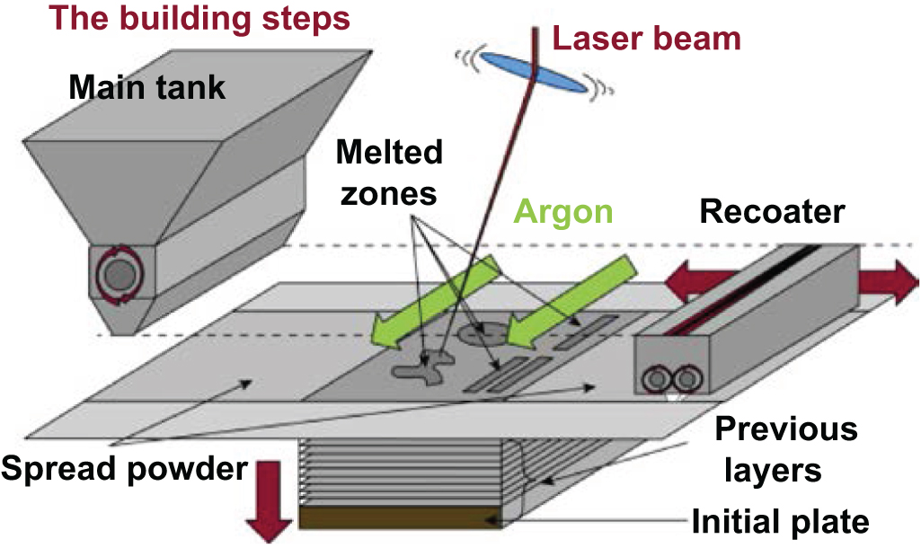
In an L-PBF process that is also known as selective laser melting (SLM), a focused laser beam is used as a heat source to selectively melt a metallic powder, layer by layer, to build 3D components. A typical configuration of an L-PBF system is shown in figure 1. When the laser energy is delivered to the required region, heat is generated locally, fusing the metallic powder, and the molten metal quickly solidifies [17]. After the solidification of the previous layer, another thin layer of metal powder (typically 30–50 μm in thickness) is spread onto the powder bed [18]. The above steps are repeated until an entire component is built [13]. Since un-melted material is not removed before the whole process is finished, it can support light features. Laser fused support structures are also often required to avoid the collapse of overhang structures and to facilitate heat dissipation [17].

Figure 1. A schematic diagram of a standard L-PBF system [19].
Download figure:
Standard image High-resolution imageHowever, the conventional L-PBF based on the blade/roller-based powder spreading mechanism is not suitable for the delivery of two or more types of materials [20]. Hence, this limitation is a barrier to utilizing a standard L-PBF system for MMAM. The latest progress of multiple metallic L-PBF, especially the development on discrete multi-materials dispensing approaches, make it possible to print at least two different materials in the vertical and horizontal directions within one component [21]. Multiple material L-PBF offers higher flexibility to produce complex multi-material 3D components with integrated multiple functions.
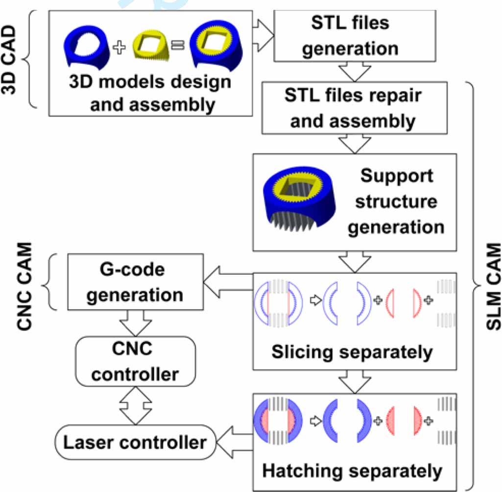
MMAM methods can print bimetallic components. However, the sharp change of material physical properties usually leads to defects and fatigue failures. A feasible solution is to add an FGM structure between two materials to make the material physical properties to change gradually. Loh et al [22] classified the volumetric gradients in those FGMs as one dimensional, two dimensional (2D) and 3D groups. Wei et al [23] described a data preparation procedure for multi-materials L-PBF, as shown in figure 2.

Figure 2. A flowchart of data preparation procedure for multi-materials L-PBF [23].
Download figure:
Standard image High-resolution image2.1. Powder delivery in multi-materials L-PBF
The simplest method to manufacture multi-material components via L-PBF is to modify the powder recoater inside a commercial L-PBF system [24]. For instance, researchers from Singapore [25] upgraded a powder feeder of a standard L-PBF system to store and deliver two powder materials separately. However, this kind of modification is only suitable for the fabrication of components with vertical dual material or multiple material variations for laboratory research purposes. Besides, the abrupt changes in the physical properties of the two materials would lead to defects, e.g. pores, cracks, and delamination at the two materials' interface, resulting in stress concentration. The complex external load in the working environment would cause residual stress to be released, resulting in the fracture of AM-processed components [26].
How to deposit different materials in the same powder layer and across different layers is a crucial step towards manufacturing of real 3D solid multi-material components via L-PBF [27]. A possible solution is to selectively deposit dissimilar materials at different regions in the same powder layer. Potential methods include: ultrasonic vibration-assisted powder deposition [28–30] electrostatic-assisted powder deposition [31–37], and pneumatic pressure-assisted powder deposition [38–41]. It should be noted that most of these methods aim to demonstrate the powder deposition concept. Few of them have been used to print actual multi-materials components.
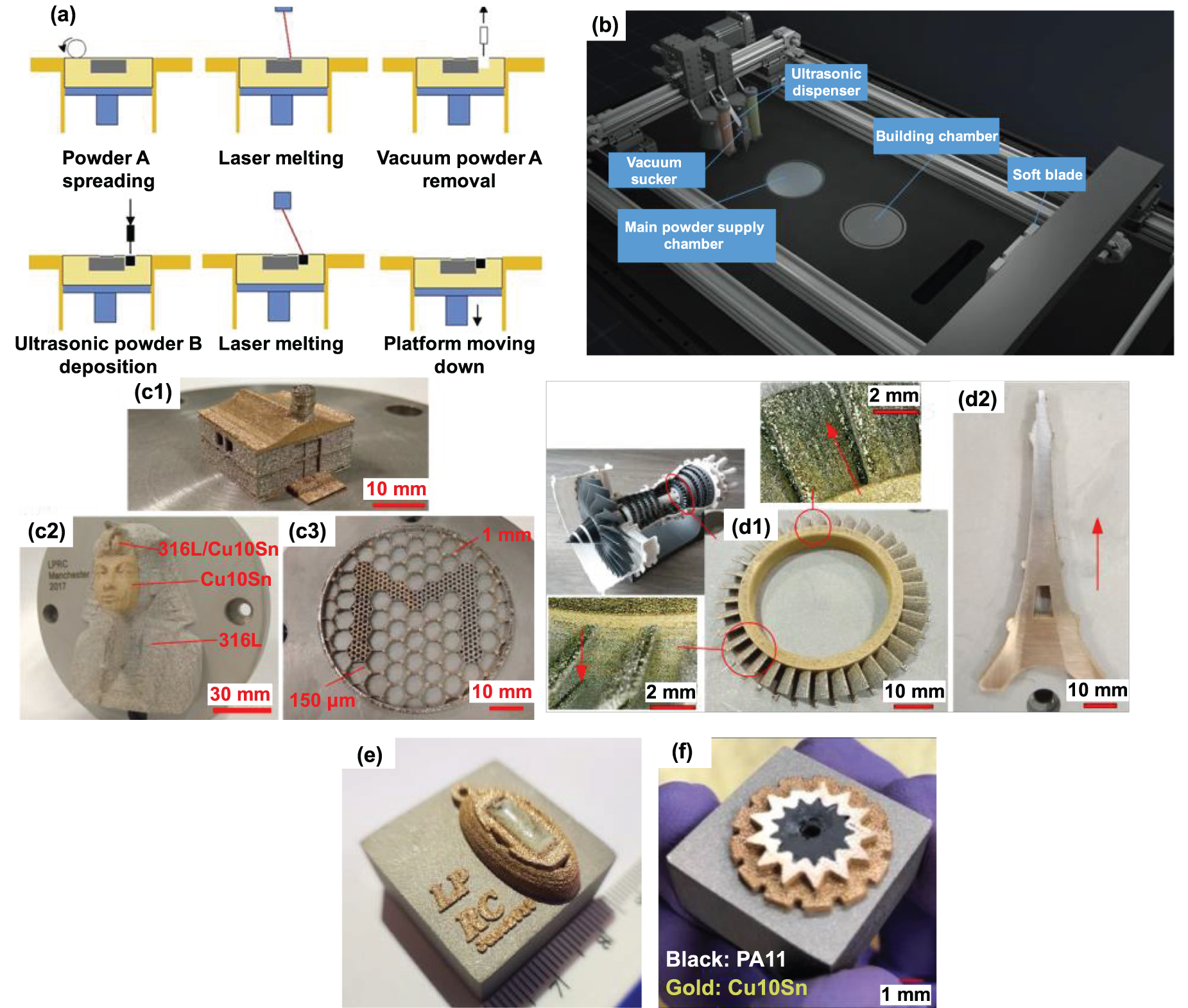
The University of Manchester in the United Kingdom developed an ultrasonic vibration-assisted precision powder feeding device (figure 3(a)) for multiple material L-PBF [23]. This method applies ultrasonic waves in a solid medium to accurately control the flow of fine powders [42] while using radial high-frequency vibration of a micro-vibration motor to continuously loosen the powder agglomeration near the powder dispensing nozzle to ensure the stability of the powder flow [43]. The needle diameter of the ultrasonic powder dispenser is about 20 times the average diameter of the powder to ensure accurate powder dispensing and the required thickness of the powder layer. This, however, also causes the ultrasonic powder dispensing speed to be slow. To address this problem, The University of Manchester researchers combine conventional powder spreading mechanism, point-by-point vacuum powder removal and point-by-point ultrasonic powder dispensing to deliver multiple materials at designed locations. As illustrated in figure 3(a), the main powder A is spread by a powder blade/roller to increase the process efficiency, and a mini-vacuum powder removal method and an ultrasonic powder dispensing method are used to precisely remove unmelted powder A and deposit the second powder B respectively. They integrated this device into an L-PBF system (figure 3(b)) to print a series of multi-material samples (figures 3(c1)–(c3)) composed of 316 l stainless steel and Cu10Sn copper alloy to verify the feasibility of multi-material L-PBF [23]. Thanks to the compact structure of this powder dispensing feeder, they integrated six powder feeders to form a powder feeding array in order to store and deposit six dissimilar powder compositions separately, and successfully used it for the manufacture of FGM parts (figures 3(d1) and (d2)) [44]. The advantage of FGM is that the physical properties (especially the thermal properties) can be gradually changed from one material to the other to avoid defects caused by abrupt changes in materials [45]. The work of The University of Manchester led to the realization of L-PBF-fabrication of multi-material parts with tailorable physical properties. Researchers at The Manchester University have further expanded the application of the above approach for AM of metal/glass samples (figure 3(e)) [46, 47] and metal/polymer parts (figure 3(f )) [48] and metal/ceramic samples.

Figure 3. (a) A process procedure of the multi-materials L-BPF technology developed by the University of Manchester [23] and (b) relevant schematic diagram of experimental setup, (c1)–(c3) L-PBF-processed 316 l-Cu10Sn samples [23], (d1) 316 l-Cu10Sn FGM turbine disk sample and (d2) Eiffel tower sample [44], (e) the Cu10Sn-glass pendant sample [46], and (f ) the Cu10Sn-PA11 sample [48].
Download figure:
Standard image High-resolution image2.2. Dissimilar metallic material components printed using multi-materials L-PBF and interface characteristics
Compared to the conventional single material L-PBF, the joining of dissimilar materials is a crucial issue during multi-materials L-PBF. Just like in the welding of dissimilar metals, the process can significantly affect the property of the whole part [49, 50]. For different material combinations, the compatibility, miscibility and thermal properties of materials need to be considered in the design stage. To achieve sound mechanical and metallurgical properties of the joints during multi-materials L-PBF, investigators studied different joining strategies, including direct joining, functionally graded joining and interlayer transition joining, which are illustrated in figure 4. Previous investigations using different metallic material combinations are classified based on joining strategies, as shown in table 1.

Figure 4. Build strategies of joining two dissimilar metals [14].
Download figure:
Standard image High-resolution imageTable 1. Summary of investigations on the L-PBF of bimetallic materials.
| Category | Material composition | Results | Reference |
|---|---|---|---|
| Direct joining method | 316 l/C18400 | •Good metallurgical bonding at the bimetallic interface because of diffusion of Fe and Cu elements; •Cracks are found in the interface because Cu diffuses into the austenitic grain boundaries; •Low UTS resulting from cracks at the interface and the high porosity in the pure Cu part. | [25] |
| 316 l/Cu10Sn | •Good metallurgical bonding between two materials; •High UTS of the horizontally combined bimetallic specimen, because of the cracks-free interface. | [51] | |
| 316 l/Cu10Sn | •Good metallurgical bonding between two materials; •Low UTS of the horizontally combined bimetallic specimen, because of cracks at the interface. | [52] | |
| 18Ni300/CuSn | •The re-melting strategy could not improve bonding strength; •Re-melting made the interface brittle and the elongation worse. | [53] | |
| AlSi10Mg/C18400 | •Good metallurgical bonding; •The intermetallic phase Al2Cu is observed; •Cracks are formed because of uneven thermal expansion and the brittle intermetallic phases. | [54] | |
| 1.2709 steel/CuCr1Zr | •Cracks and pores are formed at the interface between two materials, although there is an 0.2 mm powder overlap zone between the two. | [55] | |
| 316 l/In718 | •Cross-finger interface structure could significantly increase the contact area between two materials, improving the horizontal bonding strength. | [23] | |
| Ti5Al2.5Sn/Ti6Al4V | •The metallurgical bonding between the two materials is good regardless of annealing; •The interfacial bonding strength is always higher than that of the ti-5al-2.5sn part. | [56] | |
| Al12Si/Al3.5Cu1.5 Mg1Si | •The metallurgical bonding of the interface is good; •Un-melted Al-12Si powders are found; •The intermetallic phase Al2Cu is observed. | [57] | |
| 316 l/H13 | •Acceptable metallurgical bonding at the materials' interface; •Marangoni convection improved the two materials mixing in the molten pool. | [58] | |
| Gradient path | 316 l/MS1 | •The good bonding between layers. No visible cracks are observed. | [59] |
| method (FGM) | 316 l/Cu10Sn | •The two materials mix well during L-PBF; •Good metallurgical bonding between layers; •Un-melted 316 l powder particles are embedded in the solidified Cu10Sn alloy. | [44] |
| In718/Cu10Sn | •In718 powders at the two sides of a single track could be fully melted; •Reducing the hatch distance improves the melting status of the high melting point In718 powders. | [60] | |
| Invar36/Cu10Sn | •Low laser absorptivity and the high thermal conductivity of Cu alloy lead to unmelting of Invar36. | [61] | |
| Fe/Al12Si | •Macro cracks are observed resulting from low compatibility and miscibility of these two materials; •The microhardness result indicates a brittle intermetallic compound may be generated. | [62] | |
| Ti6Al4V/In718 | •The sample is defect-free as the In718 content is 20 W%; •If the proportion of In718 is greater than 20 W%, the brittle intermetallic phase Ti2Ni is formed and causes severe cracking. | [63] | |
| Intermediate section method | Ti6Al4V/316 l | •CuA copper alloy interlayer could avoid the formation of the intermetallic phase between Ti6Al4V/316 l; •The cracks are deflected by the α'-Ti phase from the relatively brittle TiA/CuA interface towards the ductile CuA interlayer. | [64] |
These studies indicate that a sound metallurgical bond can usually be obtained at the interface of two materials, but it is very challenging to obtain a defect-free microstructure. When the thermal properties of the two materials (e.g. Invar alloy and Cu10Sn copper alloy) differ greatly, defects such as cracks, micro-pores, and insufficient powder melting can easily occur, as shown in figure 5. At the same time, brittle intermetallic compounds and liquid metal embrittlement induced cracks are also unavoidable problems in certain multi-material L-PBF processes.

Figure 5. Microstructure of an L-PBF printed Invar36-Cu10Sn sample [65].
Download figure:
Standard image High-resolution image2.3. Effects of laser processing parameters in multi-materials L-PBF
A good understanding of the laser manufacturing process is crucial in controlling the quality of L-PBF-processed parts [66–68]. Microstructure, residual stress and thermal history are profoundly affected by laser processing parameters [69]. These parameters (e.g. laser power, laser scanning speed, energy density and hatch distance) can change the shape of melt pools, thermal gradient and cooling rate [70]. Different combinations of parameters can achieve similar energy density [71]. Therefore, energy density needs to combine with other parameters to allow a fair comparison of results. Scanning strategy can be designed to re-melt and re-heat the part to optimize surface roughness, refine microstructure and reduce porosity [72, 73].
Tey et al found that by using a higher laser scanning speed to reduce the laser energy input, a thinner Ti alloy/Cu alloy interface can be obtained which leads to a higher tensile strength [64]. Additionally, higher scanning speed results in lower temperatures in the melt pool that attributes to forming fine grains due to lower temperature gradient [74]. However, there is a limit on how far the scan speed can be increased. Too high a scanning speed would lead to insufficient laser energy input resulting in the instability of melt pool resulting in the balling effect [75]. On the other hand, Sing et al observed that a lower scanning speed can achieve higher relative density, while further reducing the scan speed leads to more large pores and unmelted particles in the samples resulted from the liquid drop splashed from the overheated melt pools [71].
Laser power highly affects the geometry of melt pool. Depth/width ratio is commonly used to identify the melting mode of melt pool. The size of melt pool is related to the laser power and laser heating time [76, 77]. Higher laser power leads to deeper melt pools. Zhao et al found that higher laser power produced a larger depth/width ratio [77]. It means that higher laser power may change the thermal transition mode from conductive to keyhole mode that can cause a unstable melt pool and increase surface roughness [77, 78]. Besides, the keyhole mode also results in the entrapment of pores [79, 80].
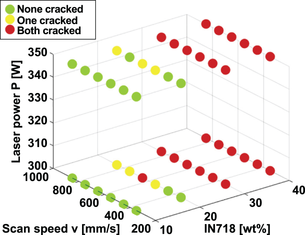
Scaramuccia et al [63] investigated the effect of laser energy density for the printing of multi-graded Ti6Al4V/IN718 components. Laser volume energy density (E) is expressed in equation (1), which is determined by laser power (P), the scan speed (v), the hatch distance (h) and the layer thickness (z) [81].
Scaramuccia et al [63] reported that excess laser volume energy density results in geometrical inaccuracy of the L-PBF-processed samples. For printing a mixture of Ti6Al4V and In718, cracks cannot be avoided for 30 wt% and 40 wt% In718 samples due to the numerous intermetallic phases. By optimizing the laser parameters, porosity-free 10 wt% and 20 wt% In718 samples can be obtained. Effects of laser power and scan speed on crack defects are presented in figure 6, which shows that the specimens with 10 wt% In718 contents have no cracks in all samples. With the content of In718 increasing to 20 wt%, cracks are presented. However, further increasing the laser power generates fewer cracks. Demir et al successfully manufactured Fe/Al-12Si multi-material components [62]. They found the fraction of cracks in the interface was increased to 5.7% from 3.3% with the laser power rising from 142 W to 236 W [62]. The fine microstructure can be obtained in the Fe side and the Al-12Si side. However, the grain size in the interface is large, which can affect the mechanical property [62]. However, by using a higher scanning speed, lower laser power and a smaller laser beam size, the grain size of the Fe/Al alloy can be reduced [82].

Figure 6. Effect of process parameters and In718 content in the blend for crack presence [63].
Download figure:
Standard image High-resolution imageKuo et al established the relationship of processing parameters, microstructure and performance of Al–Sc alloy from the analysis of melt pool interactions [83]. They found that processing parameters can affect the melt pool size and overlapping of melt pool that are related to defects and microstructure evolutions. When laser power and layer thickness are kept as constants, the samples with smaller grain sizes and higher volume fraction of small grain are obtained by choosing a slower scanning speed and smaller hatch distance. Consequently, the yield stress and density of printed materials are improved with finer grains, due to the higher cooling rate.
Hatch distance has an effect on mechanical properties of samples produced. Seede et al adopted a calibrated Eagar–Tasi model to determine hatch distance based on the geometry of melt pool that reduces the variability of mechanical properties [84]. Khorasani et al suggests that a larger hatch distance generates better surface quality by reducing overlapping through theoretical modelling [78]. Additionally, decreasing hatch distance leads to increased temperature of the melt pool that results in more partially melted powder attached on the surface of samples.
An appropriate scan strategy can reduce residual stresses, thermal deformation, and balling to avoid defects such as cracks or dimensional accuracy [85–87]. Chen et al investigated the effect of two-scan strategy for the formation of 316 l stainless steel and CuSn10 alloy [52]. The 316 l/CuSn10 structure and schematic of these two scan strategies are shown in figure 7. They found that the inter-layer staggered scanning method reduces porosity and improves the bonding strength in the transition section. The island scanning strategy helps reduce residual stresses. Lu et al found that the size of the island affects the mechanical property and residual stress of printed parts via influencing the thermal distribution in the powder bed [88]. Zou et al analyzed the scanning strategy of single laser and multi-laser scanning for residual stress by numerical simulation [72]. The scanning direction and scanning sequence for single laser have less effect in comparison to that in multi-laser scanning. However, the effects on residual stress can be reduced by carefully planning scanning direction and scanning sequence. Due to the higher heat input, the residual stress of the sample is rising with the increasing number of lasers used. They found that a two-scanning strategy, also known as re-melting, can reduce the residual stress by 10.6% compared to single scanning strategy. Yu et al reveal that re-melting can improve the surface roughness and porosity [73]. Residual particle and oxidation films in each layer are remelted by the re-melting scanning. The re-melting scanning also allows the pores to escape from the melt pool.

Figure 7. (a) 316 l/CuSn10 multi-material bimetallic structure formed by dimental-300 and (b) Schematic of inter-layer staggered scanning strategy and island scanning [52].
Download figure:
Standard image High-resolution image2.4. Mechanical properties of multi-materials L-PBF-processed samples
The mechanical property analysis of multiple material L-PBF method can be separated into two parts: one is the mechanical property of pure alloys; the other is the mechanical property of the interface or the graded transition section [25]. The overall mechanical property of finial parts such as tensile strength is highly affected by the bonding of the interface or graded transition section. The microhardness of multiple material L-PBF part is locally affected by the microstructure and the chemical composition.
The mechanical properties of two direction joining of 316 l and CuSn10 were investigated by Chen et al [52]. An example is shown in figure 7. The microhardness of the interfacial region is 212.78 ± 7.6 HV that is lower than that of the steel region (233.1 ± 8.1 HV) but higher than that of the bronze region (154.7 ± 6.0 HV). The mixing of chemical composition and the absence of Fe/Cu intermetallic compounds in the transition layer contributes to the smooth gradient of the distribution of microhardness. Horizontally combined and vertically combined 316 l/CuSn10 show ultimate strength of 459.1 ± 8.0 MPa with and 423.3 ± 30.2 MPa. For the horizontally combined 316 l/CuSn10, the ultimate strength is lower than that of 316 l SS and CuSn10 base materials because of the existing of perpendicular dendritic cracks in the interface.
In the Fe/Al12Si components, the formation of FeAl intermetallic phase improves the microhardness in the transition section of Fe/Al12Si bimetal parts [62]. The microhardness of Fe/Al12Si is 450–550 HV 0.5, which is much higher than those of Al-12Si (90–100 HV 0.5) and Fe (150–160 HV 0.5). The scanning speed and the laser power affect the microhardness and the crack proportion, respectively.
The microhardness of Ti5Al2.5Sn/Ti6Al4V has no abrupt change in the interface zone before and after annealing, due to the element inter-diffusion [56]. The tensile strength of laser-printed Ti5Al2.5Sn/Ti6Al4V is 1034 MPa is higher than the value of wrought base materials from the ASTM standard B381-13 [56]. The microhardness of Ti5Al2.5Sn is relatively lower than that of the transition section and that of Ti6Al4V base material.
In summary, as a result of improvement in powder spreading method, MMAM based on L-PBF has changed from a mere idea to a reality. Recent research shows that this method can be used to fabricate multiple metallic parts and even components with FGM structure. This would provide designers with more design freedom to achieve more complex and functionally integrated components design. The material science research for multi-materials L-PBF is still at the early stage. The research shows that the difference in physical properties of dissimilar materials can easily lead to defects at the material interface. The current stage of multi-material LPBF technology is still difficult to produce defect-free parts. Related challenges will be discussed further in the section 6.
3. Multiple metallic AM via L-DED
3.1. Introduction of multiple materials L-DED
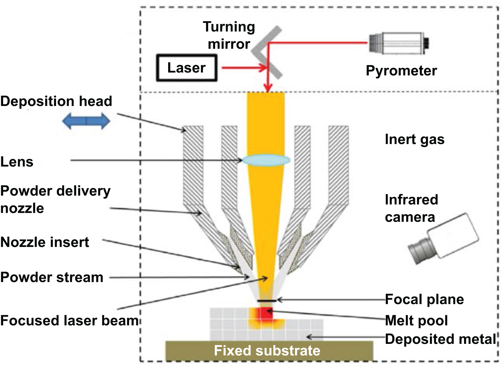
L-DED, also known as, laser metal deposition, direct laser deposition or laser engineered net shaping, a subset of direct energy deposition, is an AM technology for fabricating metal 3D solid parts by using metallic powders injected into a molten pool formed by laser beam irradiation [89]. Typical applications of L-DED include cladding, near net shape fabrication and repair of metallic components. A standard L-DED system configuration is presented in figure 8. The specific processing procedure of L-DED is as follows [90]: inert gas is usually applied as the carrier gas to deliver the powder particles from a powder feeder to the processing area. Metal powder is continuously delivered into the melt pool and is molten due to the laser irradiation simultaneously, and after the solidification of the melt pool due to heat dissipation, a track can be formed. Then, the deposition head moves up or the building substrate moves down for the next layer deposition. The above steps are repeated until the designed near-net-shape sample is manufactured.

Figure 8. Schematic diagram of an L-DED AM system [91].
Download figure:
Standard image High-resolution imageAn L-DED process is feasible to manufacture multi-material parts, as the powder materials feeding and the laser melting are simultaneous. Hence, point-to-point composition control can be achieved [92]. A typical multi-materials L-DED system is equipped with a set of powder feeders to store and feed various powders separately [93].
Muller et al [94] suggested a procedure of manufacturing multiple metallic components using L-DED. This procedure was used to fabricate a dual-material hip prosthesis.
3.2. Dissimilar metallic materials printed with multi-materials L-DED
A number of engineering metals have been successfully applied in multi-materials L-DED process including steels, Ni alloys and Ti alloys. The gradient of property change between the different materials is a major concern to fabricate multi-material components. The possible material distributions in a multi-material object, including discrete materials, gradual transition, switching between materials, a transition zone between two incompatible materials, and insoluble powder particles in the metal matrix [95].
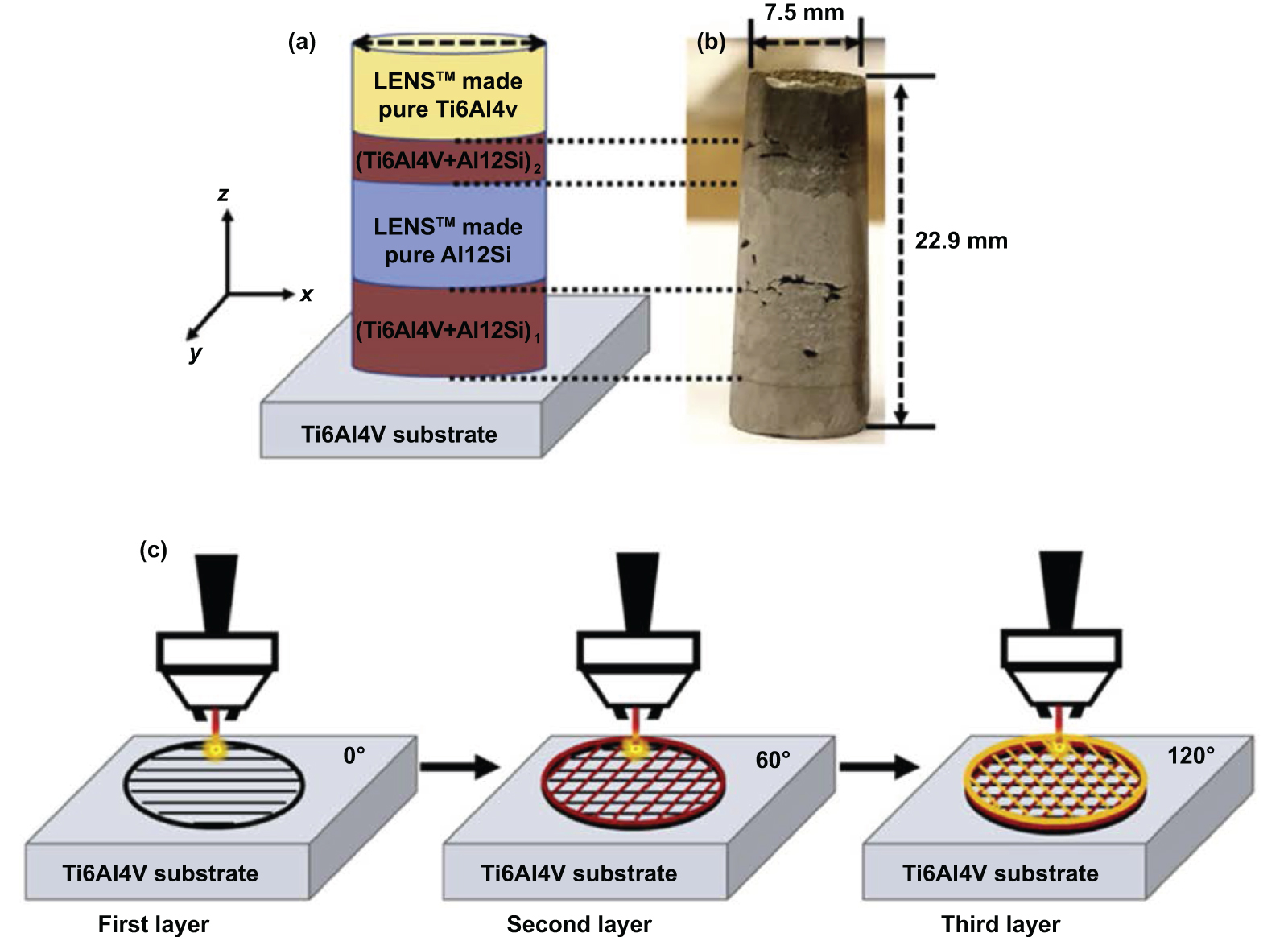
Pan et al [96] fabricated an In625-copper bimetallic structure using an L-DED process. In625 is directly coated on a Cu substrate with no cracks and a few porosities along with the interface. Compared with pure In625 components, this bimetallic structure shows improved thermal conductivity. However, it is challenging to produce a sound bonding in a bimetallic fusion zone due to the differences in the dissimilar materials thermo-physical properties. FGM can eliminate sharp interface and form a smooth transition between the dissimilar materials. A typical FGM structure can reduce the mechanical stress and thermal stress to increase the component life. Moreover, it is possible to avoid undesirable phases by controlling chemical composition. Onuike et al [97] compared the two bondings of L-DED manufactured nickel alloy (In718)/copper alloy (GRCop-84) bimetallic part: direct deposition of GRCop-84 on In718 and compositional gradation of the two alloys. They revealed that the mismatch of the properties of the dissimilar materials resulted in the failure of the directly bonded composite. In contrast, the FGM layer with tailored thermal properties increased the compatibility and improved the bonding between the dissimilar materials. Zhang and Bandyopadhyay [98] manufactured Ti6Al4V-Al12Si structures using an L-DED process, and the procedure is illustrated in figure 9. The microstructure mapping shows microstructural variation in different regions of the sample, which is influenced by both laser power and composition. A graded SS304L-IN625 component was produced with FGM interlayer by Carroll et al [93], as shown in figure 10. The microstructure, elemental composition, phase composition and microhardness were characterized across the transition region. The feasibility of building a bimetallic structure with FGM interlayer using L-DED process was demonstrated.

Figure 9. L-DED manufactured Ti6Al4V-Ai12Si part: (a) Design of the FGM cylindrical structure with a diameter of 12.7 mm. (b) The Ti6Al4V-Al12Si FGM structure after surface finishing, and (c) Schematic of the laser scanning path (0˚, 60˚, 120˚) [98].
Download figure:
Standard image High-resolution image
Figure 10. (a) Schematic of IN625-SS304L FGM specimen (b) the sectioned as-built specimen [93].
Download figure:
Standard image High-resolution imageBeside the incompatibility of the physical properties, the formation of detrimental intermetallic phases is another factor that results in failure in the joining region between the dissimilar materials. A solution to this is to use interlayers which are compatible with both base materials. A number of investigations have been reported on the manufacturing Ti alloy-steel components to avoid the formation of brittle phases. Onuike and Bandyopadhyay [99] fabricated a Ti6Al4V-SS410 bimetallic structure with an Nb interlayer. No brittle intermetallic phases, including FeTi and Fe2Ti, were found. Property tests showed increased shear and compressive strengths and good resistance to crack propagation. Li et al [100] manufactured a Ti6Al4V-SS316 part with V–Cr–Fe interlayer. This transition composition design prevented the formation of intermetallic phases between Ti6Al4V and SS316.
Investigations on L-DED processing multiple metallic materials are summarized in table 2. Multi-materials L-DED is mainly involved in copper alloy, steel, titanium alloy, and Inconel alloy.
Table 2. Summary of investigations of multiple metallic materials manufactured by L-DED.
| Gradients category | Composition | Process parameters | Properties (Increase↑, Decrease↓) | Reference |
|---|---|---|---|---|
| Sharp interface | Ti6Al4V-NiCr bimetallic structure | Laser power 375 W, feed rate 20 g min−1. | The hardness of Ti64 alloy ↑. | [101] |
| Inconel 718-Copper alloy bimetallic structure | Laser power 450 J s−1, laser scan speed 6.67 mm s−1, hatch distance 0.53 mm, layer thickness 0.10 mm. | The hardness of Copper alloy ↓; Thermal diffusivity of Copper alloy ↑. | [97] | |
| Inconel 718-Ti6Al4V bimetallic structures | Laser power was 450 W, 375 W for IN718 and Ti64, respectively. Scan speed: 8.33 mm s−1, layer thickness: 250 μm. | The micro-hardness of Inconel 718 ↑. | [102] | |
| H13 tool steel on copper alloy substrate | Laser power: 2500 W, laser scanning speed: 4.167 mm s−1 | Bond strength of H13 tool steel directly clad on copper alloy substrate and with 41 C SS buffer layer was 673 MPa, 579 MPa respectively. | [103] | |
| Functionally Graded Materials (FGMs) | Ti-Nb alloys | Laser power 1800–2000 W, travel speed 33.33–25 mm s−1, powder feed rate 0–20 g min−1 and layer height 0.5–0.8 mm. | Microhardness decrease from 250 HV0.5 at 100% Ti to 100 HV0.5 at 100% Nb. The 90% Ti—10% Nb component has the highest σm 630 ± 22 MPa. | [104] |
| Ti-6Al-4 V to SS316 | Laser power: 1000 W, 1000 W, 700 W, 550 W for V, Cr, Fe, SS316 respectively. Scan speed: 200 mm min−1, powder feed rate: 5.1 g min−1, 6.3 g min−1, 7.6 g min−1, 7.2 g min−1 for V, Cr, Fe, SS316 respectively. | Vickers hardness of Ti64 ↑ | [100] | |
| Colmonoy nickel alloy-WC/Co/Cr | Laser power: 2400 W, powder flow rate: 14.2 g min−1, the translation speed (TS): 10.33 mm s−1. | Micro-Hardness (HV0.3) of 10% Colmonoy-90% W.C./Co/Cr ↑ | [105] | |
| SS 316 l/Inconel 718 | Laser power: 450–750 W, powder mass flow rate 37.92– 50 g s−1. | Tensile strength increased with power mass flow rate and low laser power. Along 100% SS316L to Inconel 718, hardness decreases first and then rises. | [106] | |
| Interlayer | TA15 to Inconel 718 via copper interlayer | Laser power: for IN718, TA15, Cu are 1400 W, 1800 W, 1200 W respectively. Scanning speed: 7 mm s−1, powder feed rate: 7.5 g min−1. | Vickers hardness of IN718 ↑. | [107] |
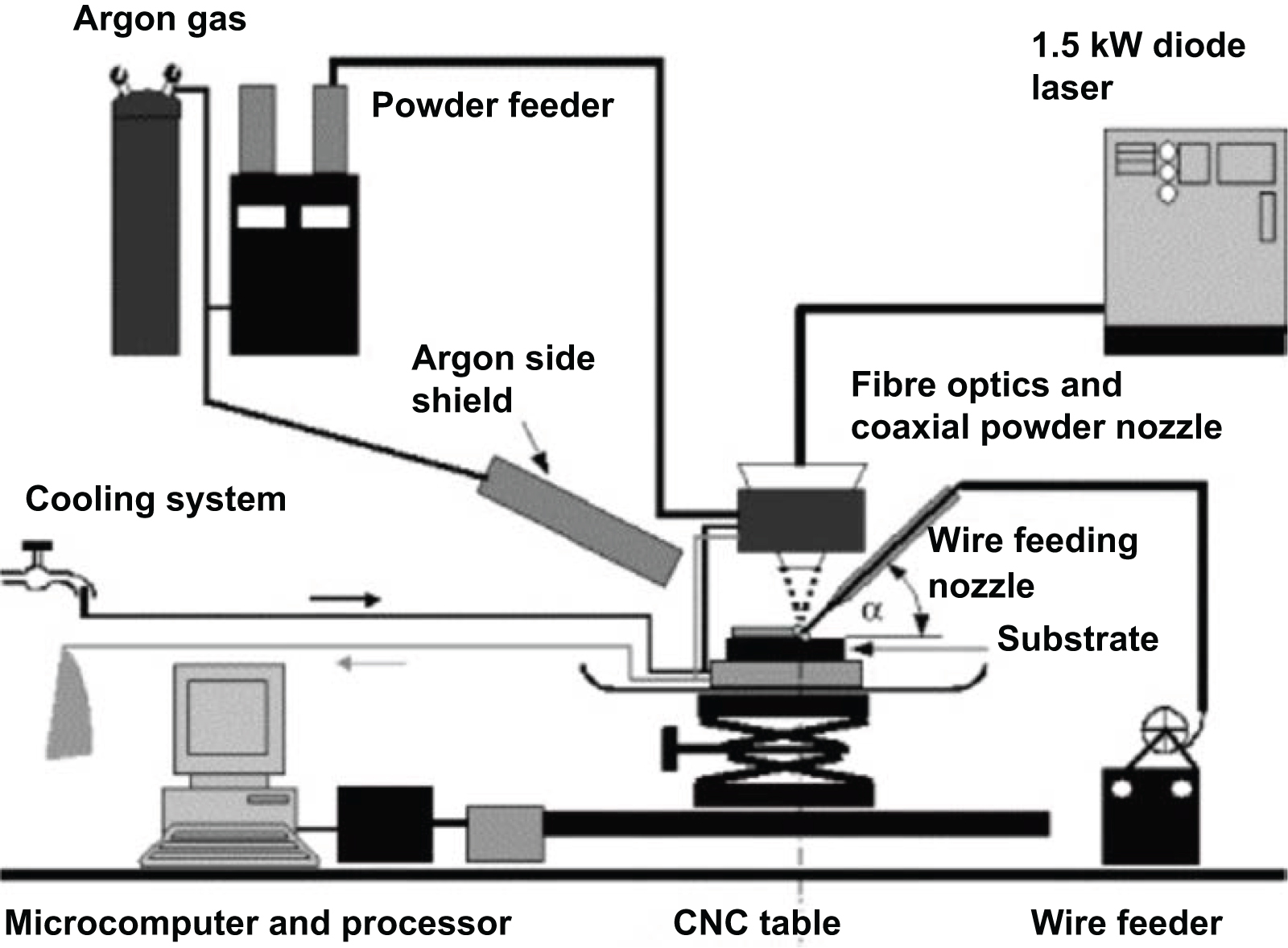
Being different from the powder-based L-DED process discussed above, investigators from The University of Manchester developed a coincident wire and powder deposition by laser (WPDL) method for L-DED printing of multiple materials and FGMs. The experimental setup of WPDL is as shown in figure 11. Due to the radiation of the moving laser beam, the surface of the metal substrate is melted and a molten pool is formed. While the wire feeder feeds the wire into the molten pool, the inert gas also delivers the metal powder into the same molten pool. Two different types of materials are melted and mixed in the molten pool to form a new alloy and allows the more wire material to be deposited at the bottom part and more powder material to be deposited on the top part [108]. By controlling the feed rate of each type of material, MMAM can be realized. This method avoids material waste and allows reuse of powders as the wire would be fully melted and un-melted powders can be recycled [109]. In addition, compared with pure powder/wire L-DED, WPDL can achieve a higher deposition efficiency and improved surface finish, while maintaining similar geometric accuracy and similar microstructure [110], because the energy absorbed by the molten pool during WPDL is more than that in wire L-DED [111]. Syed et al [112] compared functionally graded iron–nickel–copper deposition produced by 'powder–powder' L-DED and WPDL. The distribution of elements in the molten pool of 'powder-powder' L-DED shows that the large melting point difference between copper and nickel and the rapid cooling of L-DED hinder the homogenization of the element distribution in the molten pool. The molten pool temperature of WPDL is relatively higher resulting in a more uniform elements distribution in the solidified molten pool. In addition, the circulating flow directions in the molten pool of these two processes are different. The former flows from its center to its edge, and the latter flows from its edge of the upper surface of the molten pool to its center. Syed et al [113] also reported that the feed rate of copper powder and nickel wire was a key factor affecting element gradient distribution and overall mechanical properties of WPDL-processed bimetallic coating.

Figure 11. The schematic diagram of the experimental setup for WPDL [111].
Download figure:
Standard image High-resolution image4. Comparison of laser-based macro-scale multiple metallic material AM technologies
Table 3 gives a summary of various multiple material AM technologies. A single Galvo scanner can only process parts with a cross-section smaller than 250 × 250 mm due to its limitation of the effective working area. Integration of several galvo scanners in an L-PBF system can increase the effective working area for several times which is suitable for manufacturing larger components, and its processing efficiency is improved as well [114]. On the other hand, L-DED can process very large parts, as long as the travel range of drive slides of the deposition head is large enough. In terms of processing accuracy, L-PBF is better than L-DED because L-PBF uses a smaller laser spot. In summary, multi-materials L-PBF is suitable for processing high-precision small and medium-sized multi-metal parts. The multi-materials L-DED is suitable for processing large components. Surface roughness and tolerance are also critical factors in the selection of MMAM approaches. Laser beam spot size determines the melt pool size and affects the surface roughness and geometric resolution of components after laser processing. The laser beam spot for L-PBF is much smaller than that for L-DED (typically 50–80 μm, and 1.0–4.0 mm respectively [115]), which leads to better surface roughness and geometric resolution.
Table 3. Comparison of multiple metallic material AM technologies.
| L-PBF | Powder L-DED | Wire DED | Reference | ||
|---|---|---|---|---|---|
| Material | Metal, ceramic, polymer | Metal, ceramic | Metal | – | |
| Surface roughness | Ra 5–18 μm | Ra 15–60 μm | Ra 45–200 + μm | [116] | |
| Resolution | XY | 20–200 μm | 0.1–1 mm | 2–50 mm | [116] |
| Z | 20–200 μm | 0.1–1 mm | 1–10 mm | [116] | |
| Size of processed parts | Small to medium scale | Medium to large scale | Medium to large scale | – | |
In addition to the powder L-DED mentioned above, wire materials are also used in L-DED. Using wire is cheaper and allows one to use materials that are not available as high-quality powder. Wire L-DED should be a potential method for MMAM. Hence, wire L-DED is also included in table 3 for comparison.
5. Potential applications of laser-based macro-scale multiple metallic materials AM technologies
Parts used in aerospace, nuclear energy, marine industries often work in harsh environments, such as high temperature, high load, high corrosion. Hence, metallic materials with tailored physical properties are ideal for these applications. Multi-material L-PBF is an attractive tool to manufacture these special bimetallic materials [117, 118]. Typical potential applications include wear-resistant linings for processing large amounts of massive abrasive ore particles, rocket heat shields, heat engine components, heat exchanger tubes, nuclear reactors, and thermoelectric power generation machine [119]. These potential future applications combine incompatible functions via using different materials at different locations on the same components (such as hardness and toughness, high-temperature resistance, and electrical conductivity) [120].
Copper and stainless steels have significantly different thermal expansion coefficients. Löffelmann et al [121] demonstrated a bimetal plate composed of these two metals for sensing the temperature variation in aerospace applications. When the temperature is lower than 100 °C, the thermal expansion coefficient of Invar alloy is extremely low, so it is often used to produce mounting brackets for optical systems. However, the density of Invar alloy is high. Besides, the difference in thermal expansions of the two metal materials can also be used to manufacture structures with a negative coefficient of thermal expansion (CTE). For example, Mazumder et al [122] showed a nickel–chromium structure with negative CTE produced by L-DED method. This unique structure is usually used in the aerospace and optical parts to ensure that within a specific temperature range, the parts will not change in geometry due to temperature changes. Hofmann et al [123] proposed to embed Invar-stainless steel FGM parts into aerospace parts made of light-weight and high-strength carbon fibre reinforced polymer (CFRP) materials to reduce the impact of thermal deformation of composite parts on the measurement accuracy of optical parts. In718 nickel alloy maintains high strength at a high temperature, and 316 l stainless steel has excellent corrosion resistance [124]. Therefore, Locci et al [125] proposed that the In718-316 l combination can be used to manufacture micro nuclear power generation devices for space exploration. Akiba et al [126] stated that nuclear reactors can be made of tungsten-copper FGM because tungsten has the advantages of high melting point and resistance to plasma radiation, and copper has high thermal conductivity, which can improve the heat exchange efficiency of the cooling water system. Similarly, material combinations of copper–titanium alloy and copper-aluminium alloy are also suitable for heat exchangers used in the aerospace and automotive industries [127, 128]. The Fe3Al/SS316L gradient layer alleviates the low ductility of the intermetallic alloy and the sensitivity stress corrosion of stainless steel at high temperature and high pressure [129].
In addition to applying L-PBF and L-DED techniques to fabricating functional components, other important potential applications include the development of new alloys especially HEAs. The above two methods can accurately control the proportion of the powder mixture to be melted, which is beneficial to controlling the composition of the new alloy. At the same time, during the laser-based AM process, the molten metal solidifies rapidly, which makes the resulting crystal grain size smaller and can improve the mechanical properties of the alloy. In addition, the use of the above AM methods to develop new materials requires far fewer raw materials than traditional materials research methods such as smelting and casting, which will reduce costs. Laser-based AM can precisely control the temperature of the molten pool by adjusting the laser parameters, which will help improve research efficiency and speed up the development of new materials.
6. Challenges of laser-based macro-scale multiple metallic material AM technologies
Laser-based macro-scale multiple metallic material AM technologies are still in the initial research stage. Compared with single metallic material AM, there are many challenges to be faced during multi-materials AM for the formation of a dense, complete multiple metallics component with excellent properties. These are listed below.
6.1. Defects at the dissimilar materials' interface
Due to the different physical properties of multiple materials, such as melting point, thermal expansion coefficient, thermal conductivity coefficient, during AM, defects are easy to be formed at the interface between dissimilar materials.
If the thermal characteristics of the two materials are different, the cooling rate distribution and temperature distribution of the processed multi-material parts are much more complicated than those in a single material component. Therefore, deformation, delamination and cracks caused by residual thermal stress are more likely to occur at the interface of dissimilar materials.
If the melti points of the materials are significantly different and the laser absorptivities are very different, using the same laser parameters to irradiate dissimilar powder mixture will cause the high melting point powder to be insufficiently melted due to insufficient laser energy density, and the low melting point powder will evaporate due to the excessive laser energy density. Segregation of alloying elements and pores in the solidified metal in the processed material would occur. Un-melted solid high-melting point particles are often trapped in the molten pool of the low-melting point metal, which will cause stress concentration and reduce the mechanical performance of the parts.
Liquid metal embrittlement is another issue worthy of attention in the MMAM process. When a solid metal (e.g. stainless steel) contacts a specific liquefied metal (e.g. copper alloy), the solid metal loses its ductility and becomes brittle. Previous studies on multiple materials L-PBF have widely reported this phenomenon.
In addition, when two metals are melted and mixed, harmful brittle intermetallic compounds may be produced, which is also a problem that must be solved in the MMAM process.
If the density and liquid viscosity of each element in the powder mixture are very different, it is likely that the element will not diffuse sufficiently during the AM process, leading to element separation and element enrichment areas.
The above-mentioned defects at the material interface should be fully analyzed and identified during the investigations of multiple metallic materials AM, and preventive measures should be taken to avoid or reduce defects.
6.2. Powder contamination
In L-PBF, different materials are deposited on the same layer during the manufacturing process, so powder cross-contamination is inevitable. The reuse of material is challenging and should be further investigated. For the L-DED process, no extra steps are required to clean the powder bed and spread the powder. Un-used powders are mixed, and re-cycling is challenging. In the L-DED process, the biggest source of contamination comes from powder splashing, so it is crucial to control the laser scanning power and speed. Possible methods for the separation of dissimilar powders mixtures is to utilize the different physical properties such as magnetism [130], distinct particle size distribution [131], different material wettability [132], and distinct particle inertia caused by different powder density [133]. Also the use of hybrid wire and powder feeding in L-DED would avoid material contamination as the wire would be fully melted and unmelted powders can be reused [109] .
6.3. Pre-processing software
Most current AM systems use STL files as standard input. At present, there is no commercial pre-processing software for laser-based multi-materials AM. Some scholars have proposed STL 2.0 to meet the material composition [134] of each area in the positioning part.
6.4. Experimental design
Defects such as pores, delamination, and cracks, are easy to be formed during AM. For an MMAM process, the defect control is much more challenging. Parameter optimization for a single material is usually based on a large number of trial and error experiments. Each composition has a related optimal process parameter in multiple materials. Therefore, the number of experiments for MMAM, especially AM of FGM, based on conventional trial-to-error experimental methods such as orthogonal experiments and Taguchi experiments will increase by several orders of magnitude, which will undoubtedly greatly increase the time and economic cost of the experiments. It is essential to develop a multi-material calculation simulation software tool or an artificial intelligence prediction method based on single-material experimental data to predict the optimal process parameters in advance and reduce the actual experimental range.
Reichardt [135] proposed to use the CALPHAD (Computer Coupling of Phase Diagrams and Thermochemistry) thermodynamic modeling method to predict the optimal W-CuCrZr composition, which can strategically avoid regions of insolubility and intermetallic formation. Müller et al [136] described a way to identify new alloy composition through numerical simulation to increase the chance of successful new alloy development.
7. Micro multiple metallic AM via LIFT
Many emerging micro-engineering applications, including microelectromechanical systems, electronics, biomedicine, and metamaterials, involve the fabrication of micro-scale 3D structures using metallic materials [137]. Micro-scale AM approaches include direct ink writing, electrohydrodynamic Printing, local electrophoretic deposition, meniscus-confined electroplating, electroplating of locally dispensed ions in a liquid. Laser-induced photoreduction, focused electron/ion beam induced deposition, and LIFT provide flexible routes to fabricating 2D and 3D metallic geometries with 0.1–10 μm resolution [138]. LIFT is especially suitable for printing micro-scale components composed of dissimilar metallic materials, resulting from its non-contacting materials delivery mechanism.
7.1. Principle and experimental setup of LIFT
LIFT is a digital printing process. It uses the energy provided by the laser pulse to peel off the donor thin film attached to optical transparent carrier in the form of voxels and make it jet to receiving substrate and finally deposit on it. Repeating the above steps can form microscale 3D objects [139]. Except for the original LIFT demonstrated by Bohandy et al [140] in their investigation on depositing copper onto a silicon substrate using an excimer laser source, there are many variations of LIFT. The LIFT of metal films and LIFT of high-viscosity suspensions have been widely investigated for AM of 3D micro geometries.
7.1.1. Solid LIFT (LIFT of metal films).
The experimental setup (see figure 12(a1)) for LIFT of metal films is comprised of an optical transparent carrier substrate, e.g. a glass slide coated with a thin metal layer, and a receiver. The mechanism of the droplet formation during LIFT of metal films was described by Adrian et al [141] and Willis et al [142]. The thermal energy provided by the pulsed laser beam heats the interface between the carrier and the thin metallic donor layer, causing locally melting of the metallic layer. The melt front of the molten pool propagates along with the thickness of the metal layer until it reaches the free surface at the center of the laser spot. In this status, the temperature at the interface is higher than the melting point of the metal donor; hence the molten metal near the interface will be vaporized. The resulting vapor pressure ejects the molten metal from the donor layer and forms a droplet, which flies toward the receiver. The liquid metal droplet lands on receiver substrate, then cools and solidifies quickly.

Figure 12. (a1) schematic diagram of solid LIFT and (a2) a Cu pillar printed by this method, the microstructure of which is shown in (a3); (b1) the schematic diagram of fluid LIFT and (b2) an Ag pillar printed by this method, the microstructure of which is shown in (b3) and (b4) [137].
Download figure:
Standard image High-resolution imageFigure 12(b1) presents a schematic diagram of a LIFT-based AM system using a metal film as the donor material. The laser optical path system is stationary. The carrier with a donor layer moves horizontally with respect to the laser beam so that the new donor material can be irradiated by the laser and form droplets. The receiver moves horizontally to make droplets land to predetermined positions to form a pattern. The gap distance between the donor layer and the receiver ranges from 10 μm to 1000 μm, which can be adjusted by raising and lowering the receiver.
7.1.2. Fluid LIFT (LIFT of high-viscosity suspensions).
In addition to transferring solid-phase donor materials to the receiver, LIFT can also transfer suspensions containing metallic particles to the receiver substrate [143], especially high viscosity paste with metallic particle size ranging from nanometers to tens of micrometer [144]. High viscosity paste is usually used for screen printing, soldering or stencilling. In this type of applications, the laser beam is shaped by an aperture [144] or a digital micromirror device [145] and then irradiated on the suspension layer, so a voxel with the laser beam shape is transferred to the receiver. Hence, the shape and size of voxels are easy to be controlled. This method is suitable for forming 2D geometry at one time, which significantly improves the processing efficiency. The vapor to make the metallic particles ejected from the carrier substrate is formed by rapid evaporation of the solvent in the metallic particles suspensions [146]. This process is also known as laser decal transfer [147]. A simplified experimental setup is illustrated in figure 12(b1). Notably, the metal particles landed on the receiver are un-melted. Hence it is essential to use an adequate annealing post-heat treatment to sinter all particles [148].
7.2. The microstructure of LIFT-printed samples
A copper pillar and a silver pillar were fabricated via the above two approaches, respectively, in the investigation done by Reiser et al [137], as shown in figures 12(a2) and (b2). The pillar fabricated by LIFT of Ag nanoparticle paste has better surface roughness and structural integrity than that processed by LIFT of Cu film. In the solid LIFT process, the metal film donor has been melted during jetting, and there is an irregular pore distribution in the stacked part, as shown in figure 12(a3). In the fluid LIFT process, the suspensions containing metallic particles is directly transferred to the receiver substrate with a designed pattern. The metal particles in the paste have no phase change, so the deposited part presents defect-free cross-section, as shown in figure 12(b3). However, after the annealing treatment, the liquid in the paste evaporates, the metal particles are sintered, the part appears apparent pores, and the density of the parts presents a gradient. As shown in figure 12(b4), the outer area of the pillar is denser, the size of pores is smaller, and there is a hollow in the center of the pillar. The density of the parts printed by LIFT is low, which will affect its mechanical properties. Hence, LIFT is not suitable for the potential applications needing full-dense and good mechanical strength. On the other hand, the high porosity in the LIFT-printed components can increase its contact surface area, which is an advantage for catalysis, optical metamaterials, and power storage devices applications.
7.3. Donor materials in LIFT
LIFT can deposit a wide range of donor materials, which are summarized by the publication [149], as shown in table 4. Silicon, silica, copper, polyimide, Ceramics, metal, and quartz can be used as the receiver substrate materials [150]. Optical transparent materials, e.g. glass, fused silica, quartz, and transparent polymer (e.g. PET) are generally applied as the carrier substrate materials [151].
Table 4. Materials for LIFT [149].
| Category | Material |
|---|---|
| Metals | Cu, Ag, V, Cr, Ti, Sn, W, Pd, Al, Au, Ni, NiCr, Zn, Pt |
| Oxides | YBaCuO, BiSrCaCuO, In2O3, V2O5, BaTiO3, Y2O3, Y3FeO2, Ruthenium oxide, MnO2, Ag2O, LiCoO2, ZnSiO4:Mn, GdGaO |
| Polymers | PMMA/colored dyes. Polyethene, OLED |
| Intermetallic | FeSi2 |
| Carbon | Diamond, nanocomposites, graphite, carbon nanotubes |
| Biomaterials and living cells | Fibroblastskeratinocytes, endothelial cells, human osteoprogenitors, Escherichia coli, mammalian cells, DNA, proteins, embryonic cells, fungi |
7.4. Multiple metallic material printing via LIFT and applications
LIFT has a wide range of applications, including printing 3D micro-scale metallic structures, energy storage components, electronic components, biomolecules, biochemical sensors and cells, and even directly transferring functional devices to the surface of other parts [152]. Among them, the first two application fields mainly involve metal or multiple metallic materials.
7.4.1. LIFT of 3D micro-scale metallic structures.
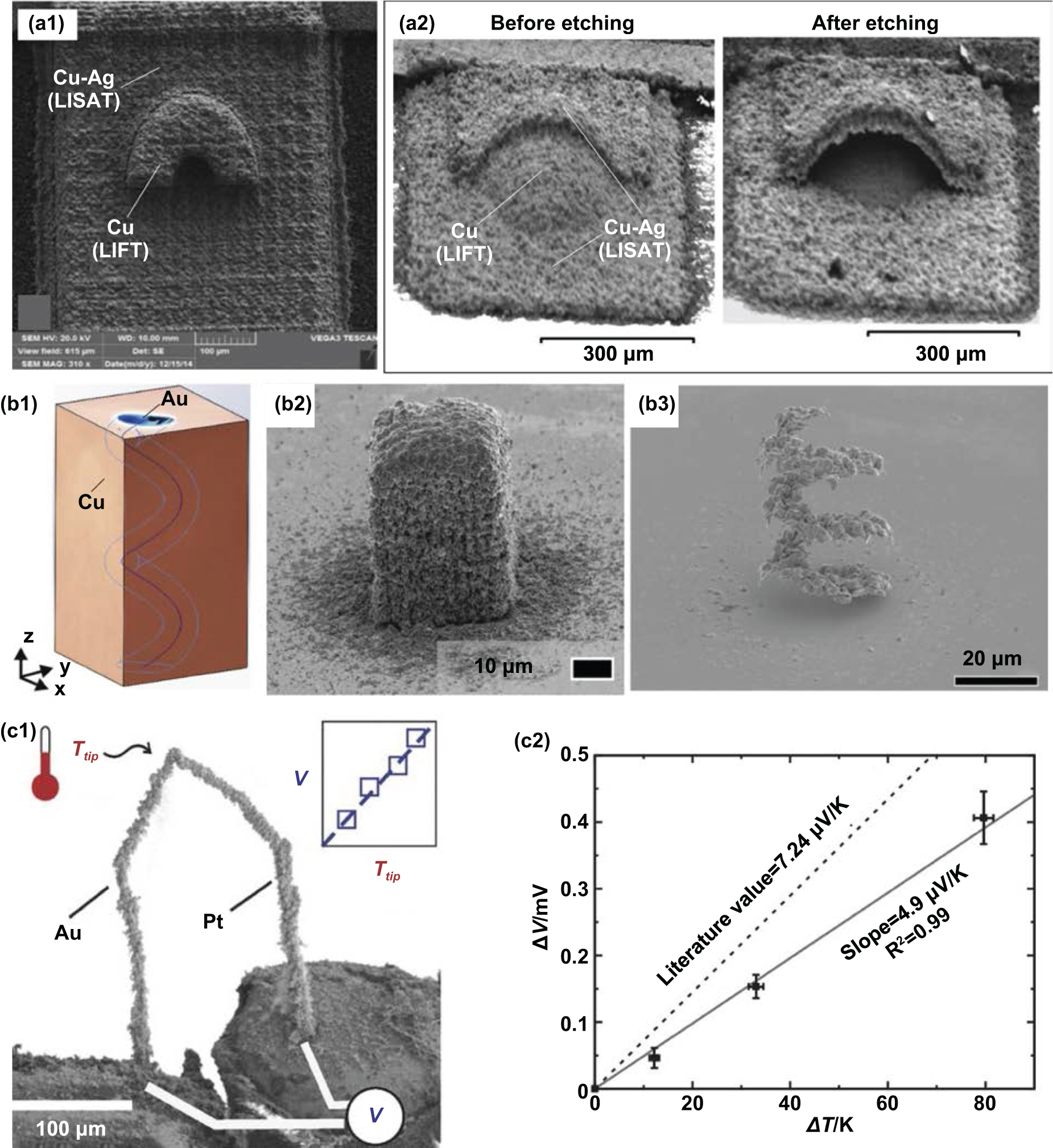
Zenou et al [10] showed a combination of LIFT method and modified LIFT method (laser-induced self-alloying transfer (LISAT)) for fabricating Cu–Ag 3D parts (see figures 13(a1) and (a2)). The pure copper material in the pictures is processed by LIFT, and the copper-silver alloy is processed by LISAT. The key contributions of this work include: sub-micrometer resolution pure copper and Cu/Ag alloy multi-material structures can be printed on heat-sensitive substrates in the ambient condition, the processed parts are not oxidized, and no sintering post-heat treatment is required; secondly, the LISAT method demonstrated by the authors uses high-frequency pulse laser locally melts the donor layer composed of dissimilar material films, and different elements are melted and self-alloyed during the droplets jetting from the donor carrier.

Figure 13. (a1) a sample with a LIFT-printed Cu half ring on the top of a LISAT-printed Cu/Ag slab, (a2) a LISAT-printed Cu/Ag half dome with a LIFT-printed Cu support structure [10]; (b1) the 3D object design of an Au helix embedded in a Cu sacrificial support structure, (b2) the LIFT-printed Au–Cu combination, (b3) the Au helix after etching [153]; (c1) a micro Au–Pt thermocouple printed via LIFT, and (c2) its temperature vs voltage measurement plot [154].
Download figure:
Standard image High-resolution imageSimilarly, Feinaeugle et al [153] demonstrated LIFT-processed Cu sacrificial support structures for LIFT-printed free-standing gold helix structure, the 3D object design of which is as shown in figure 13(b1). The printed Cu and Au combination is presented in figure 13(b2). After the ferric chloride etched the Cu part, the free-standing gold helix structure was appeared (figure 12(b3)). Its feature size is smaller than 10 μm, and its surface roughness ranges from 0.3–0.7 μm Ra.
Luo et al [154] demonstrated a LIFT-printed micro Au-Pt thermocouple which is featured by its high-aspect-ratio pillars, as shown in figure 13(c1). At different temperatures, the voltage measured by the thermocouple has a linear relationship with the actual temperature, as plotted in figure 12(c2). The author stated that the LIFT method should be feasible for the fabrication of micro functional devices (e.g. micro-actuators, inductors, chemical sensors) for transient measurement and control.
7.4.2. LIFT of power storage components.
As shown in figure 13, the LIFT-printed micro 3D objects are composed of solidified microdroplets. Hence they have high porosity and high surface area. This feature is advantageous for electrochemical devices. Because the effective contact area between the electrode with high porosity and the electrolyte is larger, resulting in better charge transfer efficiency. Therefore, researchers have studied the use of the LIFT method to print electrodes for miniature power storage devices (such as supercapacitors and micro-batteries) [155].
7.4.2.1. LIFT printed multiple material battery.
Kim et al [156, 157] demonstrated the processing procedure based on LIFT for the fabrication of solid-state Li-ion micro-batteries, as shown in figure 14(a1). In their work, the thick-film electrodes, including LiCoO2 cathode and carbon (mesocarbon microbeads, MCMB) anode, were printed via LIFT. The discharge capacities of the micro battery with LIFT-processed thick-film electrodes (see figure 14(a4)) is much higher than that with thin-film electrodes produced by the conventional sputter-deposition because the highly porous structure of the LIFT-printed electrodes (see figures 14(a2) and (a3)) allows Li-ion diffusion in those electrodes easily without obvious internal resistance.

Figure 14. (a1) the processing procedure based on LIFT for manufacturing Li-ion micro battery, (a2) the high porous microstructure of LIFT-printed (a2) LiCoO2 cathode and (a3) MCMB anode, and (a4) the cross-section of the LIFT-printed Li-ion micro battery [156].
Download figure:
Standard image High-resolution image7.4.2.2. LIFT printed supercapacitors.
In addition to batteries, supercapacitors are another power source used in consumer electronic products. The advantages of supercapacitors include long cycle life, no memory effect, high safety, maintenance-free, and simple charging circuit [158]. The characteristics of graphene include a large surface area, excellent chemical stability, and good electrical conductivity. Therefore, graphene is an ideal material for making electrodes used in supercapacitors [159].
An important factor restricting the miniaturization of electronic devices is the size of power storage devices. The latter depends on the dimensions of its electrodes. Shen et al [160] reported a method of using a femtosecond laser to reduce graphene oxide to fabricate miniature electrodes of micro-supercapacitors. As shown in figure 15(a2), the fingers of these electrodes have a length of 100 μm, a width of 8 μm, and a spacing of 2 μm. Subsequently, the authors used the LIFT method to accurately drop the electrolyte droplets onto the top of each electrode to avoid excessive electrolyte immersing other electronic components and causing interference. The entire processing flow is shown in figure 15(a1). The authors found that the mesoporous structure produced in graphene and small-sized electrodes with narrow wides and small hatch distance can effectively improve ion diffusion and enhance the electrochemical performance of supercapacitors, including a high specific capacitance (6.3 mF cm−2 and 105 F cm−3) and ∼100% retention after 1000 cycles.

Figure 15. (a1) the processing flow combining laser direct writing and LIFT for the fabrication of (a) ultraminiature graphene micro-supercapacitors [160]; (b1)–(b6) the processing flow for fabricating graphene/nickel foam electrodes, (b7)–(b9) the microstructure of nickel foam at different stages [161].
Download figure:
Standard image High-resolution image
Although the supercapacitors using graphene electrodes mentioned above perform well, they are challenging to integrate with metal current collectors, so the method discussed above is not suitable for manufacturing large-capacity electrodes. Li et al [161] reported another technique of 3D printing graphene/nickel composite electrodes for large-capacity electrochemical power storage. As shown in figures 14(b1)–(b6), the authors first deposit graphene on nickel foam through the LIFT method, and then enhances the lattice matching between the additively printed graphene and the nickel current collector through laser annealing heat treatment, repeating the above two steps until an entire electrode is fabricated. At different stages, the microstructures of nickel foam are shown in figures 14(b7)–(b9). The supercapacitor with graphene/nickel foam composite electrodes presented excellent electronic performance, including high electrical conductivity (359 712 S m−1), high retention rate (> 98% after 10 000 cycles), large areal specific capacitance (995 mF cm−2), and high power density (9.39 mW cm−2).
8. Conclusion and future perspective
In this paper, we summarized the research progress on laser-based MMAM technologies (including L-PBF, L-DED, and LIFT) for macro-and micro-scale fabrication of metallic materials. Applications and challenges are discussed.
In macro manufacturing, with the breakthrough of the technical bottleneck of multi-material powder feeding mechanisms, the use of L-PBF and L-DED to produce multi-material parts has become a reality. The promising potential applications of the above technologies include the manufacture of FGM parts used in aerospace, marine, nuclear energy, and medical industries, which are also known as functional mechanical parts. Currently, the above two AM methods are still in the preliminary stage for the manufacture of FGM, and there is still a significant knowledge gap to archive the final goal of processing defect-free FGMs and use them in practical industrial applications. The reasons leading to the above problems are as follows. Firstly, the material composition and laser processing process parameters have dramatic impacts on the microstructure of AM-processed samples, the phase transition, the formation of intermetallic compounds and the final mechanical properties. FGM parts usually are composed of two or more materials with very different physical properties. How to make the same set of laser parameters applicable to multiple materials at the same time and generate defect-free microstructures is very challenging. Secondly, the material composition proportion in FGM parts is constantly changing, which means that a set of optimal process parameters must be prepared for each material proportion. The related experimental workload is geometrically higher than that of traditional single-material AM. So, traditional research methods are no longer suitable for research on AM of FGM. Thirdly, the current commercial phase transition prediction software and simulation & modeling software are usually designed for single-material processing and lack the thermodynamic databases required for multi-materials processing. Therefore, it is challenging to optimize FGM processing by predicting. To solve these problems, investigators must develop new research strategies, including the use of artificial intelligence technology to design processing parameters and material composition, reducing the volume of actual physical experiments. At the same time, use phase transition analysis software such as CALPHAD to predict the phase transition and eliminate the proportion of material components that will produce harmful phases; During the experiment, using in-situ monitoring approaches, for instance, infrared imaging camera, high-speed camera, and pyrometry-based system [162], to observe the occurrence of defects, close-loop control the manufacturing process and store data [163]; After the experiment, machine learning can be used to identify in-situ melt pool signatures indicative of flaw formation based on the defect data collected in the experiment, find the rules, and then optimize the processing parameters and material composition [164].
In micro-manufacturing, solid LIFT and fluid LIFT are currently the main processes that use lasers as energy sources to produce micron-scale 3D metal objects. The material transfer method of LIFT is very suitable for processing multi-metal material in the same component. Because this method can deposit solid thin films as well as liquid inks, there is no contact during the LIFT deposition process, which completely avoids the material cross-contamination problem in the macroscopic AM process mentioned above. At the same time, LIFT can handle a wide range of donor materials, including metals, oxides, intermetallic compounds, and even biological materials and cells. Besides, there are many candidate materials as the receiver substrates during LIFT, including metals, optically transparent materials, flexible polymers and so on. Therefore, different combinations of donor materials and receiver materials can be applied to different application fields. In addition to the micro-scale metal functional 3D structures and energy storage components mentioned in this paper, LIFT can be combined with other AM methods to print conformal electronic circuits on the surface of AM-made objects, and even directly print tissues and organs in the biomedical field. However, porosity is a problem that is difficult to avoid during LIFT printing of metallic materials, which will affect the mechanical properties of LIFT-printed parts. Therefore, LIFT is not suitable for processing micro metallic components that require high density and high mechanical properties. On the other hand, the pores caused by LIFT can increase the surface area of the LIFT-printed parts, which is beneficial for certain applications involving electrochemical reactions such as power storage devices, catalysts, and optical metamaterials. Therefore, future research on LIFT could be in these areas.
In the past decade, the laser-based AM research community has conducted extensive research on various material combinations in order to achieve the purpose of printing dissimilar materials on the same component in one process, and it has been proved that different AM methods can be used to process multi-materials metal parts as large as meter-scale and as small as micrometer-scale. These investigations laid a foundation for the transition of laser-based MMAM technologies from laboratory research to commercial applications. Laser-based MMAM technologies have obvious advantages in simplifying the manufacturing process, increasing design freedom, and reducing the time and costs of prototype manufacturing, compared with conventional manufacturing methods. Before the wide use of laser-based MMAM, there are still many challenges. The promising application of MMAM determines that future MMAM research will be multidisciplinary involving mechanical engineering, manufacturing engineering, materials science, electronics, photonics, biology and other disciplines. How to integrate complex hybrid manufacturing systems, to establish design and manufacturing rules, to optimize manufacturing processes, to in-situ monitor and control manufacturing quality, to assess long-term reliability of printed parts need to be further studied. Solving these challenges will require tremendous efforts, but with the development of applications ranging from aerospace to power storage and the participation of industrial users, solutions will be found to these problems.