
Abstract
With the maturity of surgical robotic systems based on traditional rigid-link principles, the rate of progress slowed as limits of size and controllable degrees of freedom were reached. Continuum robots came with the potential to deliver a step change in the next generation of medical devices, by providing better access, safer interactions and making new procedures possible. Over the last few years, several continuum robotic systems have been launched commercially and have been increasingly adopted in hospitals. Despite the clear progress achieved, continuum robots still suffer from design complexity hindering their dexterity and scalability. Recent advances in actuation methods have looked to address this issue, offering alternatives to commonly employed approaches. Additionally, continuum structures introduce significant complexity in modelling, sensing, control and fabrication; topics which are of particular focus in the robotics community. It is, therefore, the aim of the presented work to highlight the pertinent areas of active research and to discuss the challenges to be addressed before the potential of continuum robots as medical devices may be fully realised.
Export citation and abstract BibTeX RIS

Original content from this work may be used under the terms of the Creative Commons Attribution 4.0 license. Any further distribution of this work must maintain attribution to the author(s) and the title of the work, journal citation and DOI.
1. Introduction
In the last two centuries, healthcare procedures have changed dramatically. This has been possible due to technological breakthroughs that have enabled the development of new medical devices and techniques [1]. One of the most successful examples is the endoscope. This device allowed surgeons, for the first time in the 19 century, to look into their patients' bodies through natural orifices and wounds as opposed to making fresh incisions [2, 3]. This has impacted screening and intervention, which has also shifted towards less invasive methods and given rise to minimally invasive surgeries (MIS) such as laparoscopy or natural orifice trans-luminal endoscopic surgery (NOTES) [4]. These present several benefits to the patient when it comes to blood loss, recovery time, post-operative trauma, scarring and wound site infection [5]. However, they can be challenging from the surgeons' point of view due to differences in ergonomic control, sensory feedback, dexterity and intuitiveness [6–8].
These limitations and the need for better and improved medical procedures have paved the way to robotically-assisted medical interventions. This has in turn allowed clinicians to perform procedures with more precision, flexibility and control while decreasing procedural times and complications to the patient [9]. Medical robots have come a long way since their inception in the 80 s when a standard industrial robot was used to secure a fixture in place for neurosurgery [10]. The release of the da Vinci Surgical System (Intuitive Surgical, Inc. Sunnyvale, CA, USA) in the early 2000's further heightened the interest in this field. In 2018 more than 1 million procedures worldwide were carried out with the da Vinci system alone [11].
The majority of medical robotic systems in use today rely on rigid instruments with dexterous wrists at the tip. This restricts their movements due to the low number of degrees of freedom (DOF) exhibited [12, 13], hindering the robot's adaptability and safe patient interaction [14]. More recently, continuum robots (CRs) have emerged and are gaining major interest as an alternative to standard rigid-link robots. CRs are able to generate smooth curvilinear motions exhibiting infinite DOFs and, as such, have the potential to reach further into the body with reduced tissue trauma through MIS and NOTES (figure 1) [13]. The use of CRs in medical robotic platforms consequently allows for improvements in existing procedures and the development of new and better techniques. This has recently been illustrated by the launch of several continuum platforms such as Monarch™ (Auris Health, Inc. Redwood City, CA, USA) and Ion (Intuitive Surgical, Inc. Sunnyvale, CA, USA).

Figure 1. Applications of medical continuum robots to access hard-to-reach areas in a minimally invasive manner. These include the cardiorespiratory system, the digestive system, head and neck, the urogenital system and the vascular system.
Download figure:
Standard image High-resolution imageDespite previous reviews on the topic of medical CRs [15–18], the abundance of attention and development on the topic warrants an updated review. Therefore, in this article we provide an overview of the current challenges that this class of robots face which currently inhibit the realisation of their full potential. We begin the review by presenting the main application areas for medical continuum robots given the current state of the art. We then provide an introduction to the field of CRs followed by an overview of the current actuation methods. We then describe the challenges that these robots face according to their fabrication, modelling, control and sensing; and conclude by providing a comparison between methods and recommendation for future research.
2. Applications of medical continuum robots
2.1. Brain interventions
Open brain surgery is still a common procedure, especially in emergency situations, however MIS has been gaining popularity such as in electrode implantation and endovascular coiling for intracranial aneurysm [19–21]. Since 2010, the robotic system ROSA® Brain (MEDTECH, Inc. Montpelier, France) has been used to perform a variety of these procedures. Lower procedural times and higher accuracy and precision are among its benefits, proving the effectiveness of robot-assisted brain interventions over conventional methods [22].
Most brain procedures (manual or robotic) still employ rigid, straight instruments, limiting the possible paths between the entry point and the target [19]. The use of continuum robotic systems that are able to conform to curvilinear paths will enhance brain MIS; delivering wider freedom to suitable procedures. To this end, some flexible devices, such as magnetic needles [23], have been emerging but remain too stiff to provide increased path freedom.
2.2. Lung interventions
Effective trans-oral bronchoscopy for lung biopsy is a key element in early diagnosis of lung cancer [24, 25]. However, traditional bronchoscopes are restricted to movements only along the lung's bronchial tree limiting procedural efficacy [26]. Continuum robotic systems for a deeper, more consistent and stable bronchoscopy have long been an area of interest. The commercial release of the Monarch™ (Auris Health, Inc. Redwood City, CA, USA) and Ion (Intuitive Surgical, Inc. Sunnyvale, CA, USA) platforms, in 2018 and 2019 respectively, are great examples of systems targeting this need. By using ultra-thin bronchoscopes and catheters, these robotic devices are able to reach further into the lung when compared to conventional bronchoscopes [27–29]. The use of CRs for lung biopsy has resulted in improved control, dexterity and freedom of movement through the airways.
Beyond diagnosis, robotics for treatment of pathologies of the respiratory system has also been emerging; including standard medical robotic platforms alongside newer continuum systems, such as the cable-driven Flex® Robotic System (Medrobotics, Raynham, MA, USA) [30, 31]. However, due to their lack of dexterity and increased size, these systems have thus so far been limited to head and neck interventions [32]. As such, there have been considerable efforts to allow robotic surgery deeper into the trachea and bronchial tree. Indeed, the Virtuoso Surgical (Virtuoso Surgical Inc. Nashville, TN, USA) system recently demonstrated treatment of a central airway obstruction [33] and is an example of progress in this direction
2.3. Endovascular interventions
Continuum structures have long been manually inserted into blood vessels and manipulated to the desired location to treat endovascular and heart conditions in a minimally invasive manner [15]. As can be expected, precise manual catheter navigation and placement is challenging, requiring the surgeon to undergo extensive training. Aligning these existing devices and procedures with robotic navigation and steering is a potential solution to overcome this limitation.
Over the last decade, several robotic navigation and steering systems for guide-wires, stents and catheters have been released, such as Magellan and Sensei (Hansen Medical, Mountain View, CA, USA) and CorPath GRX (Corindus, Inc. Waltham, MA, USA). These systems have been used in a variety of procedures from peripheral vascular to neurovascular interventions [34–40]. Robotic navigation of magnetic catheters has also seen significant progress with systems such as the Stereoaxis Niobe® Robotic Magnetic Navigation System (Stereotaxis, Inc. St. Louis, MO, USA) [41]. These navigation systems, in addition to enabling higher accuracy and precision, are also capable of reducing exposure to radiation and contrast agent for patients and clinicians by being remotely controlled and cutting procedural times [42]. Building on robotic control, autonomous catheter navigation is also now being investigated, however this is still at an early development stage [43].
2.4. Gastroenterological interventions
Currently early screening of cancers of the gastrointestinal (GI) tract is performed via traditional endoscopy or wireless capsule endoscopy (WCE) and, despite their achievements, both methods have their limitations [24, 44–47]. Endoscopes are known to cause tissue damage and discomfort for the patient, whereas WCE lacks active locomotion, tissue interaction and lumen diameter adaptation [46–49].
To this extent, robotic alternatives to these two methods have been reported. Robotically actuated endoscopes are able to improve comfort and reduce pain for the patient by providing an alternative to manual handling and navigation [31, 50, 51]. Robotic alternatives to WCE have mainly focused on achieving active locomotion [52, 53], but ultimately, the capsules' wireless characteristic limits their application to screening only. Additionally, robot assisted GI surgery is common across several procedures, such as removal of liver tumours or the gallbladder, using systems such as the da Vinci [54–57]. Due to the lack of dexterity exhibited by the instruments, open surgery is still the preferred method in some cases. Emerging treatment procedures using continuum micro-robots have been reported, such as the deployment of patches for stomach ulcers [58] or targeted drug delivery [59, 60]. These technologies, however, are still at a very initial development stage.
2.5. Urogenital interventions
Robotic interventions in the urogenital system have long been common for specific procedures such as prostatectomy or nephroureterectomy [61, 62]. However, single-port systems deployable through natural orifices are required to further reduce invasiveness and to treat alternate pathologies. To this extent, a lot of attention has been given to research on continuum robots for urogenital interventions.
Continuum robots to replace rigid resectoscopes used in bladder cancer diagnosis [63, 64], hand-held manipulators for laser prostate surgery [65], or even flexible fetoscopic instruments addressing twin-to-twin transfusion syndrome [66, 67] are some of the proposed devices in the area. However, currently there are no commercial platforms available. Given the presence of a natural orifice, such as vagina and urethra, the use of continuum robots in this area may deliver several benefits.
3. The rise of continuum manipulators
3.1. Past and present of continuum robots
Traditional robots are composed of discrete rigid links connected by joints and are able to move with high precision and accuracy, making them highly suitable for tightly controlled and repeatable tasks. However, there are often limitations when operating in small and confined spaces where adaptability, dexterity and safe interactions with the patient are necessary [13, 17]. As previously mentioned, the recent coupling of manually steered continuum structures with robotic actuation and control has provided more intuitive and easier to use systems increasing the benefits to both the surgeon and the patient.
Continuum robotic systems can be the innovation needed across several areas of medicine, where current healthcare practices have limited efficacy due to access and safety. Furthermore, replacing straight rigid devices with continuously deformable structures may allow better navigation inside the body through conformation to the patient's anatomy and provide safer physical interaction. Steering and navigating such devices, however, poses significant challenges.
3.2. Definition and classification of continuum robots
CRs can be defined as actuated structures that form curves with continuous tangent vectors [17]. These robots are considered to have an infinite number of joints and DOF, allowing them to change their shape at any point along their length [14]. These characteristics make them ideal for variable environments where flexibility and adaptability to external conditions are necessary.
Continuum manipulators (CMs), structures that resemble an elephant's trunk or an octopus' tentacle, have been gaining popularity for medical applications. These typically have a small diameter and exhibit high dexterity in order to reach confined spaces, such as the lung's bronchi. The design of such structures is, on its own, a challenge given that higher dexterity normally comes associated with a higher number of actuators. This increases the diameter of the structure, which in turn decreases the range of motion [17].
The demand for safer tissue interactions has led to the development of soft robots. This emerging field comprises robots made of intrinsically soft elastomeric materials, giving the robot the ability to absorb energy and deform to their surroundings and external constraints [68]. They are, therefore, highly compliant and flexible, enabling a vast range of complex motions [69]. Soft robots are by definition CRs as they can deform continuously having infinite DOF [70, 71]. Additionally, they exhibit deformation whereas hard CRs only exhibit flexibility. Medical soft robotics have shown possibilities from targeted drug delivery to minimally invasive procedures [59, 72].
4. Actuation of continuum manipulators
4.1. Mechanical actuation
Mechanical actuation refers to the use of solid elements to directly transmit forces and torques through or within the actuator structure. Driven in part by the requirement of high dexterity at small scales for medical interventions, mechanically driven continuum robots have successfully branched from classical serial designs. Given the variety of approaches taken, an abundance of robot designs have emerged, being broadly categorised into steerable needles, concentric tubes and backbone-based [17, 73, 74]. Generally, the order presented here reflects an increase in design complexity and force output, although specific implementations vary. Figure 2 illustrates example implementations utilising these design principles and table 1 summarises many of the mechanically actuated designs proposed in the literature for specific medical interventions.
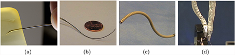
Figure 2. Mechanically actuated continuum robot designs for varied actuation principles; showing: (a) the steerable needle concept [75], (b) a typical concentric tube design [76] and backbone-based designs (c) tendon driven [77] (copyright © 2015, Springer Nature) and (d) multi-backbone [78] (copyright © 2009 by SAGE Publications).
Download figure:
Standard image High-resolution imageTable 1. Summary of mechanically actuated medical robots.
| Ref | Design principle | Application | Actuation | Diameter (mm) | Controllable DOF | Length (mm) | Min. bending radius (mm) |
|---|---|---|---|---|---|---|---|
| [79] | Bevel tipped steerable needle | MIS | 0.7 | 3 | - | - | |
| [80, 81] | Notched steerable needle | Brachytherapy | Ultrasound guided | 3.2 | 3 | - | 171 |
| [82, 83] | Concentric tube | MRI guided surgery | 3 piezoelectrically actuated tubes | - | 6 | 567 | 72 |
| [33] | Concentric tube | Central airway obstruction | 2 motor driven dexterous arms | <2 | 3 each | - | - |
| [84] | Monarch™: Concentric tube | Bronchoscopy | Cable driven | 4.2 | 10 | - | - |
| [77] | Backbone | Neuroendoscope | 2 tendon driven bending sections | 3.4 | 1 each | 120 | - |
| [85] | Backbone | Single-site partial nephrectomy | 2 tendon driven segments | 26 | 2 each | 240 | 76 |
| [86] | Backbone | Laparoscopy | Cable driven with compressible spring backbone | 8 | - | - | - |
| [87] | Backbone | Neurosurgery | Tendon driven extensible backbone segments with tendon driven bending | 21 | - | 340 | - |
| [88, 89] | Backbone | Cardiac surgery | 50 tendon driven serial links | 10 | 105 in total | 300 | 35 |
| [78] | Backbone | Throat MIS | 2 multi-backbone segments with push-pull actuation | 4.2 | 20 | 35 | 8.13 |
4.1.1. Steerable needle designs
Steerable needles form their continuum shape exclusively through interaction with the tissues. Development of robotically controlled needle insertion methods has been driven by the aim of accurately and precisely reaching target locations within tissues through non-linear pathways in order to avoid obstacles or delicate structures. Initial designs typically relied on the uneven forces produced at the bevel tip of the needle to steer along curved trajectories [90]. Rotation of the needle with variable duty cycle enabled path control [91, 92].
Over the years, a number of developments have been proposed in an attempt to minimise tissue damage during insertion and reduce the radius of curvature. Needles with kinked bevel tips [93], or with a concentric sleeve and needle stylet [94] have been reported. Furthermore, needles with flexures [75] and notches [80, 81] to reduce tip stiffness have also been proposed. Different steering methods have also been developed using tendons [95, 96], through magnetic actuation [19, 23] and by using water jets [97]. Steering has also been achieved utilising interlocking translating sections inspired by the wasp [98, 99] and an over tube [100]. Despite their achievements, this type of continuum robots ultimately relies on tissue damage for actuation.
4.1.2. Concentric tube designs
As their name implies concentric tube actuators result from the nesting of pre-curved tubes, typically made from nitinol (NiTi), within one another [76, 101, 102]. With relative rotation and translation, varied sets of curvature are achievable with a further increase in workspace possible through coupled motions. Although first presented for generic needle-steering and surgical applications [76, 101], specific formulations have since been presented for: neurosurgery [103] including endonasal [104, 105]; transurethral prostate surgery [82, 106]; lung access [107] for biopsy [108] and central airway obstruction removal [33]; and needle driving through elastic instability [109].
These applications highlight the immediate benefit of concentric designs as their ability to be realised at small scales, allowing access through the narrow tortuous pathways of the body. However, unlike steerable needles, concentric tubes rely on a change in length to induce varying curvature. Additionally, limitations in pre-curvature of tubes limit their path-following capabilities and require design parameter optimization to match application specific trajectories [110]. Furthermore, the payload that can be supported through concentric tube implementations is an important limitation of their interventional capacity.
4.1.3. Backbone-based designs
A widely adopted approach for realising continuum actuator design is the use of an elastic central backbone. This spine supports the elements required for actuation while its elastic properties produce continuous bending and restoration forces; returning the actuator to a neutral (ordinarily straight) position upon the removal of actuation forces. A number of materials have been employed for this function, such as springs [77, 111, 112], polymers [113–115] and NiTi rods/tubes [78, 116].
With a central elastic structure in place, tendons or rods are routed along the length of the backbone, held to the desired routing pathway through the use of spacing discs and fixed to a specific distal point. Although similar in form tendon driven embodiments produce actuation force only under cable tension, while rod driven (multi backbone) is rigid in tension and compression, resulting in a stiffer overall design. Upon loading, the tendons/rods transmit forces to the termination point resulting in bending-inducing torques. Increased DOF can be achieved by serially stacking actuation segments of this design.
Routing of the actuation element is a key variable in determining the manipulator's performance. Usually, routing configurations per segment are comprised of one or two antagonistic pairs for single or bi-planar bending respectively, or three actuating elements spaced evenly around the central axis of the actuator. A generalised model for tendon routing for single-segment designs [117] and two-segment designs [118] has been proposed. These show that helical tendon routing increases workspace and enhances obstacle avoidance. Radial variation in tendon path routing has also been recently explored [119], illustrating the ability to significantly increase tip stiffness with non-parallel tendons. Although tuning of this nature enables varied actuator design, once implemented the kinematic and dynamic properties are largely invariant. However, features to allow variation in design during operation have also been investigated. Magnetic spacing discs have been used to form extensible segments [116], leading to the possibility of follow-the-leader and path following motions [110, 120]. Alternative designs for achieving extension/contraction include a tendon driven concentric backbone [87] and the use of two interlaced lockable continuum robots [121]. In addition to variable kinematics, designs have also been presented to allow stiffness adjustment through antagonistic tendon-fluid bladder configurations [122–124], pressure/vacuum jamming techniques[85, 125–127], using shape memory alloys [112], or insertable constraints[128].
The benefits of backbone designs reside in their large range of motion and configurability. With the addition of multi-segment, variable length designs and tuneable stiffness, they are highly suited to surgical applications. However, scaling down these designs is challenging, in part due to high levels of hysteresis introduced from internal friction and tension loss within actuation cables, which ultimately limits their scope.
4.2. Fluidic actuation
Fluidic actuators operate under the principle that a confined fluid applies any pressure change evenly throughout its volume. Any anisotropic strain limiter included in either the material properties or the material topography will produce correspondingly anisotropic deformation [129]. The fluid employed in these actuators highly influences their performance. In medical applications, the fluids more commonly employed are water and air, hydraulic or pneumatic respectively, given their availability, regulation and disposal and safety to the patient [130]. Pneumatic systems are preferred due to the low viscosity of air which is crucial for miniaturisation. Its compressibility, however, can reduce the system's controllability and introduce lag [131]. Fluidic actuators are able to achieve bending, twisting, extending and contracting through different designs, such as artificial muscles and fluidic elastomer actuators. In table 2, a summary of medical robots utilising fluidic actuation is presented.
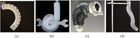
Figure 3. Pneumatically actuated continuum robots; (a) pleated [132, 212] (© 2018 WILEY-VCH Verlag GmbH & Co. KGaA, Weinheim) and (b) corrugated [133] (copyright © 2013 WILEY-VCH Verlag GmbH & Co. KGaA, Weinheim) FEA manipulators, (c) the "Belloscope" tip driven endoscope [134] (copyright © 2018, IEEE) and (d) the STIFF-FLOP multi-modal system [135] (reproduced from [135]. © IOP Publishing Ltd. All rights reserved).
Download figure:
Standard image High-resolution imageTable 2. Summary of fluidic actuated medical robots.
| Ref | Design principle | Application | Actuation | Diameter (mm) | Controllable DOF | Length (mm) | Maximum bending angle (deg) | Maximum pressure (kPa) | Max. force (N) |
|---|---|---|---|---|---|---|---|---|---|
| [136] | PAM | Direct cardiac compression | Pneumatic | <14 | - | 140 | - | 100 | 50 |
| [66] | McKibben artificial muscles | Fetal surgery | Pneumatic | - | 2 | - | - | - | - |
| [135] | FEA | MIS | 3 pneumatic modules | 25 | 1 | 165 | 240 | 72 | - |
| [31] | FEA | Colonoscopy | Hydraulic | 18 | 5 | 60 | 130 | 6.1 | 7.9 |
| [137–140] | FEA | Gastroscopy | Hydraulic waterjet | 12 | 3 | - | 94 | 32.8 | 0.10 |
| [141] | FEA | MIS | 2 pneumatic modules | 32 | - | 135 | 132 | 65 | 7.9 |
| [134, 142] | Parallel bellows | Gastroscopy | 3 pneumatic bellows at the tip | <14 | 3 | 120 | 65 | - | - |
| [143, 144] | Serial bellows | Endovascular | 2 hydraulic segments | 3 | - | 80 | - | - | - |
4.2.1. Artificial muscles
Artificial muscles are characterised by an axial contraction when pressurised [136, 145]. The McKibben muscle is considered to be the original fluidic actuator and consists of an inner tube enclosed in a flexible double-helix braided sheath responsible for contraction [145]. This actuator is known for providing a high power to weight ratio.
With advances in manufacturing capabilities over the past 25 years, other variants of artificial muscles have emerged, such as pneumatic artificial muscles (PAM) [145]. These employ the same principle as the McKibben muscles but by varying wrap angles and densities of the external sheath, the topology of deformation under pressure can be manipulated [146, 147]. PAMs are able to achieve lighter per unit force than other alternatives, greater compliance and zero static friction, preventing jumps during actuation [145]. These characteristics are of particular interest to the surgical robotics community from a safety perspective and their use has been reported in cardiac compression devices [136].
4.2.2. Fluidic elastomer actuator
Fluidic elastomer actuators (FEA) consist of synthetic elastomer films with embedded channels which expand and/or bend when pressurised[68, 148]. It is a wholly soft structure and its strain limiter is built into the material's geometry. This total absence of rigid material enables a robot with a much greater range of movement and which is, in general, safer in contact with human tissue. FEAs also operate at lower pressures than artificial muscles due to their lack of fibrous support [131]. This enables easier actuation but limits the maximum force the robot can exert.
FEAs come in a range of different topologies offering different solutions to various problems such as cylindrical tubes [135], eccentric tubes [149], pneumatic networks [130, 150], corrugated membranes (ribbed [131] or pleated [151], see figures 3(a) and (b) and helically restricted elastomers [152]. All these options offer variants of anisotropic strain limited geometry, generating highly non-linear deformations which, when incorporated with the natural compliance of the material, produce shapes completely unachievable in traditional hard robots or with artificial muscles. This highly non-linear behaviour is, however, difficult to model and control. Furthermore, large deformations can be viewed as problematic when navigating confined spaces such as those within the human body. There is also a risk of rupture due to their unconstrained pneumatic bladders. When operating in sensitive environments and near sharp objects, such as surgical blades, this is rightly considered a real risk.
4.2.3. Emerging actuators
Recently a number of innovative alternative actuators have been developed. One example is actuation via micro-jet propulsion [153]. Despite the potential demonstrated by this method, further safety developments should be addressed such as disposal of actuation fluid in a comfortable manner and ensuring the minimisation of tissue damage by the propulsive jet. Other interesting examples include a robot which is steerable and controllable by growth [154]; and peristaltic motion [155].
In addition to emerging fluidic actuation methods, a large effort has been made to develop safer alternatives from a rupture point of view. One such example is the fibre-reinforced FEA [156] which dopes the elastomer with microfibres turning any potential rupture into a slow puncture. Approaching the same issue from the opposing perspective, series PAM (sPAM) replace the original fibrous sheath with additional pneumatic actuators creating a fully soft actuator with similar power delivery capabilities to the original PAM [157]. Furthermore, self-sealing polymers [151] and vacuum actuated elastomers [158, 159] have also been reported.
4.2.4. Actuator arrangements
Typically one actuator will provide one primitive motion [160]. Continuum robots, especially for medical applications, must be capable of multi-directional deformations [161]. This is most readily achieved via modular actuation [135].
In modular actuation, several actuators are connected with the ramification that each independent actuator must have its own supply line [135]. Actuators may be connected in series to create slender continuum manipulators [147], in a parallel and un-conjoined arrangement to create, for example, grippers [162], or in a parallel and conjoined arrangement for multi-directional manipulators [163]. A common approach is to connect actuators both in parallel and in series as in the STIFF-FLOP project [135] shown in figure 3(d). This robot features ten independently operated actuators each with a 1.5 mm diameter driveline. The robot itself has a diameter of 25 mm illustrating one of the major limiting factors for the application of fluidic actuators to continuum robots' miniaturisation. Obviously, future improvements in manufacturing technology can assist but the trade-off between manipulability and size is a chronic and yet unresolved issue. Some alternatives to address this issue have been reported, such as the use of Band Pass Valves to reduce the number of drivelines [143] but the traditional limitations of miniaturisation still apply with regards to manufacturing technology.
4.3. Magnetic actuation
Magnetic actuation of robots relies on the use of magnetic forces and torques; generated through manipulation of the magnetisation of the robot and the external magnetic field in which the robot is placed. This type of actuation eliminates the need for bulky on-board systems allowing easy miniaturisation and untethered control, both useful for the medical robot applications. Furthermore, magnetic fields are proven safe for clinical applications, having been in use for several decades [164].
Robot designs with time-varying magnetic properties placed under constant fields are challenging to fabricate and present safety concerns due to heat dissipation [165, 166]. For these reasons, magnetic robots for medical applications almost exclusively have constant magnetic properties and are placed inside a varying magnetic field for manipulation [165]. Over the past two decades, advances in the use of magnetism in robotics have led to different ways of incorporating magnetic properties and to the development of novel actuation and navigation systems. Table 3 lists several of the magnetically actuated continuum robots presented in the literature.
Table 3. Summary of magnetically actuated medical robots. Deflection is shown in mm (minimum bending radius) for hard devices and in degrees (deformation angle) for soft devices.
| Ref | Design principle | Application | Actuation | Diameter (mm) | Length (mm) | Deflection | Inovation |
|---|---|---|---|---|---|---|---|
| [168, 170] | Permanent magnet | Heart ablation | Magnetic tip for steering | <2.5 | 50 | 7 mm | Variable stiffness segments allowing shape forming |
| [19, 23] | Permanent magnet | Neurosurgery | Magnetic tip for steering | 1.3 | - | 100 mm | Magnetically guided steerable needle |
| [49, 50] | Permanent magnet | Colonoscopy | Magnetic tip for steering | 20 | 22 (active tip) | - | Robotic alternative to manual endoscopes |
| [169] | Permanent magnet | Endovascular | Two magnets along along the body | 0.5 | 3.8 | 132.7° C | High deformation angles |
| [175] | Permanent magnet | MIS | Magnetic tip for steering | 3 | 47.5 | 54° C | Titanium robot with flexures along the body |
| [171] | Polaris X™ Permanent magnet | Electrophysiology | Tendon drive with magnets for steering | 2 | 1500 | - | Commercially available soft magnetic catheter |
| [174] | Magnetic particles | Cerebrovascular | NdFeB in PDMS tip | 0.6 | 3 (active tip) | <90° C | Fully sub millimeter magnetic robot |
| [176] | Magnetic particles | Cerebrovascular | Three NdFeB sections along the body | 2 | 42 | - | Fully soft shape forming robot |
4.3.1. Device's magnetism
Embedding magnetic properties in continuum robots has been easily done by inserting permanent magnets in their structures. By optimising the location, number and distance between the magnets, the robot can achieve the desired application [167]. This approach is fairly common with a variety of designs and applications reported, such as the guide-wire for cardiovascular applications shown in figure 4(a) [168–170]. The major advantage of using permanent magnets is that their properties are well known, facilitating the modelling and control of the device. Additionally, the use of components already designed for and used within, clinical settings facilitates the pathway to commercial adoption. In fact, several magnetically steered catheters are already available on the market, such as Polaris X™ Catheter [16, 171]. However, the use of permanent magnets imposes limitations in terms of size and achieving fully soft structures.

Figure 4. Magnetically actuated continuum robots; (a) embedded permanent magnets [169] (© Sungwoong Jeon et al 2019; published by Mary Ann Liebert, Inc.) (b) magnetic composite polymers [174].
Download figure:
Standard image High-resolution imageAlternatively, one can use magnetic composite polymers. These polymers are characterised by the introduction of magnetic micro or nano particles into a polymer matrix [172]. This results in a magnetisable mixture whose characteristics, such as mechanical properties and suitable manufacturing methods resemble the original ones [172]. By inducing a patterned magnetisation profile into structures made out of these polymers, one can achieve fast transformations into complex 3D shapes and locomotion capabilities [173]. An example of continuum robots that employ such composites can be seen in figure 4(b). Further information about the challenges of fabrication and inducing magnetisation patterns can be found in section 5.1.
4.3.2. Actuation systems
Unlike the previous actuation methods where the limitations were mainly due to the on-board design, magnetic actuation is limited by the external conditions one can generate, in this case, magnetic fields and magnetic field gradients [177–179]. Over the past two decades, a number of actuation systems for magnetic robots have been developed and can be fundamentally classified into either coil-based or permanent magnet-based, depending on the source of the magnetic field.
Coil-based systems
Coil-based systems are able to generate both homogenous and inhomogeneous magnetic fields by controlling the input electric current. Uniform magnetic fields can be generated by Helmholtz coils [180, 181]. These rely solely on magnetic torques for actuation, given the lack of a magnetic gradient. Maxwell coils, alternatively, achieve both force and torque actuation. Due to their design simplicity, these systems achieve low controllable DOF [182–184]. Several systems with a high number of electromagnetic coils have been proposed achieving higher number of controllable DOF [185], such as Minimag [186] and OctoMag illustrated in figure 5(a) [187]. A system capable of fulfilling the theoretical maximum of eight DOF was also recently reported [188]. More recently, emerging systems consisting of moving electromagnetic coils [189] and a magnetic-acoustic hybrid actuation have been reported [190].
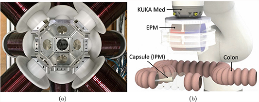
Figure 5. Magnetic actuation systems; (a) coil-based system Octomag (MagnebotiX AG, Zurich, Switzerland) [187] (image used with permission from MagnebotiX) and (b) permanent magnet-based system [50] (copyright © 2019, IEEE).
Download figure:
Standard image High-resolution imageGenerally, coil-based systems have high controllability and stability [191]. However, they are associated with bulky equipment, small workspace, up-scaling limitations and prohibitively high cost. In fact, adapting these systems to a clinical setting might be a difficult task without loss of the DOF achieved in the research environment.
Permanent magnet-based systems
Permanent magnet-based systems provide a feasible alternative to electromagnetic coils. These do not rely on real time electrical currents to generate a magnetic field, allowing for stronger fields and field gradients while not suffering from overheating problems [50, 192]. Two approaches using permanent magnets have been reported, rotating permanent magnets and robotic manipulation of permanent magnets. Rotating permanent magnets, while providing the advantages of permanent magnets, still suffer from reduced workspace [192, 193]. Alternatively, mounting permanent magnets at the end effectors of robotic manipulators and moving them around the desired workspace can be easily translated into the clinical environment given its much larger workspace [194, 195]. This method has been used for a variety of continuum devices, such as that depicted in figure 5(b) [50, 196].
Despite the advantages of permanent magnets over electromagnetic coils, these systems come with their own limitations. Any changes to the generated fields are performed via mechanical methods, introducing mechanical noise in the system. Furthermore, the non-linear relationship between the magnetic field and induced wrench makes robotic control less straightforward.
4.3.3. Magnetic navigation systems
Successful magnetic steering depends not only on reliable magnetic actuation but also on simultaneous monitoring. Magnetic navigation systems based on imaging techniques and electromagnetic tracking have emerged to address this issue.
Imaging
The high quality and real-time nature of x-ray monitoring systems made them the favoured technique for magnetic navigation. Both coil-based and permanent magnet-based systems using x-ray have been reported [41, 167, 170, 197]. Despite the good results achieved, the risks associated with x-ray exposure are a major limiting factor and have encouraged further development of monitoring systems.
Modified magnetic resonance imaging (MRI) machines have emerged as a candidate navigation system [198, 198–201]. In fact, MRI fringe fields have been used for steering continuum magnetic robots [202]. However, the lack of simultaneous monitoring and feedback and the need for more reliable control hinder these systems' use. Ultrasound based monitoring provides a safe, cheap and reliable alternative approach. Their usage in magnetic navigation has been explored [59] and used to provide closed loop navigation in endoscopy [203].
Electromagnetic tracking
Navigation of other actuation methods can be done with the aid of common electromagnetic tracking systems, such as Aurora (Northern Digital Inc. Waterloo, Canada). However, these are incompatible with magnetic actuation due to distortions caused by both the external actuation field and the device's magnetism [49, 204]. This being so, alternative methods have been proposed such as the the incorporation of magnetic field sensors and inertial sensors in the robot to determine its pose [49]. An alternative approach sees the placement of a two-dimensional array of magnetic field sensors in the workspace, facilitating miniaturisation of the device [204].
Despite the promising results shown by tracking approaches these are limited to permanent magnet-based actuation systems. Tracking within magnetic fields generated by coil based systems is not possible due to the high number of singularities present.
4.4. Summary
Mechanical, fluidic and magnetic actuation methods for continuum robots have given rise to a variety of designs. Overall they are well suited for the medical community despite each having its own limitations.
Mechanical and fluidic methods, although abundant, suffer from trade-offs in terms of size, stiffness and controllable DOF. Many designs presented achieve high levels of dexterity, however, to realise the higher number of DOF, larger diameters are typically necessary. Considering mechanical actuation specifically, the relative rigidity and non-compliance can pose a significant safety risk during tissue interaction, necessitating mitigation through complex control strategies. In fact, steerable needles cannot achieve their small bending radii without causing some tissue damage.
Conversely, fluidic robots inherently address this issue given their structural softness and compliance. However, the risk of rupture in these devices during pressurisation still needs to be addressed in an effective and safe way. Furthermore, the relatively low forces they exert opposes progression against device-tissue friction in tortuous anatomy. Solutions that are able to achieve higher forces at lower operating pressures and with improved patient-specific design may offer safer and more effective options.
Magnetic CRs share many of the inherent benefits with mechanical and fluidic devices, with the addition of being able to achieve much smaller diameters due to the dearth of internal design required, such as cable routes or fluidic channels. Furthermore, the controllable DOF are dependent on the external actuation system, which permits miniaturisation of the device without loss of controllability. This becomes extremely useful when considering endovascular or brain procedures where thin devices are needed. One major drawback when using magnetic composite polymers is biocompatibility. Although solutions are well established for fluidic devices [163], for magnetic CRs the issue persists. Solutions such as coating the devices with biocompatible materials have been reported [174], but further studies in this area are still needed.
A final but crucial consideration for these approaches is the off-board actuation system used. This has been thoroughly explored in the literature for mechanical and fluidic devices, as they rely primarily on well-established and effective robotic methodologies such as cable transmission and pneumatic pumps. Magnetic devices, however, represent a much more recent technology and exhibit less straightforward control strategies. This has hindered a quick and easy implementation of concepts. As such a wide diversity of magnetic actuation strategies have emerged dependent on the requirements of the specific application, however, significant exploration on this topic is still required.
5. Challenges associated with continuum manipulators
5.1. Fabrication
Medical continuum robotics is an emerging field with some examples of devices now breaking into the market. As the technology further matures, the development of effective manufacturing processes that enable greater function and decreased size scales will be essential to growth of the field. This has been shown in soft robots, where innovation in manufacturing processes has illustrated new modalities of actuators, design freedom, sensing and operation.
Fabrication of mechanically actuated robots is well established as they are commonly produced by standard subtractive manufacturing techniques (e.g. milling or electrical discharge machining). However, the use of alternative methods, such as 3D printing, to allow for patient- or procedure- specific customisation has been reported [205], as well as methods to facilitate fabrication of concentric tubes [206]. Given that fabrication for fluidic and magnetic robots is a considerably newer area of research and less explored in the literature, in this paper we first focus on fabrication of polymeric, flexible structures normally employed in soft robotic devices. The focus then shifts to magnetic continuum structures where new fabrication strategies and magnetisation techniques present significant opportunities for increased function within robotic surgical devices.
5.1.1. Soft lithography
Soft lithography is a common technique for producing continuum structures due to its low barrier to entry. The process relies on the accurate replication of features from a master by casting a liquid polymer. Once cured, the polymer can be removed to reveal a negative of the mould. It has been shown that some examples of closed chambers can be produced by assembling components through plasma bonding or using uncured elastomer as an adhesive [131].
This method is suitable for limited life materials often used for experimental continuum devices. Its resolution is also limited by the minimum achievable feature size of the master mould. In practice, this usually requires a compromise between mould expense, production time, material suitability and resolution. Photolithographic techniques can be used to produce high resolution patterns, but production time and cost can be prohibitive. The accessibility of additive techniques/3D printing techniques has increased the use of master moulds due to low lead times and costs. However, resolution restrictions are often higher and several of the mould materials induce a reaction that inhibits curing of silicone elastomers.
Multi-material structures are also a challenge for soft lithography, with each change in material significantly adding to production time. Over-moulding higher stiffness materials is often used to introduce spatially varying mechanical characteristics and induce a bending bias during operation [68]. Selective inclusion of functional elements, such as conductive nano-particles, can only practically be achieved via homogenous distribution throughout the body.
Furthermore, the process is fundamentally 2.5D since the final device needs to be removed from the mould without damage. Lost wax and dissolvable moulds have been used to enhance the complexity of the designs, but their single use increases manufacturing timescales and expense. Creative designs have been important in allowing more complex behaviour in multi-link continuum robots. However limited achievable complexity using these mould based methods has led to direct additive or even hybrid techniques being increasingly investigated.
5.1.2. Direct addictive manufacture
Direct additive manufacture (AM) has been increasingly used to investigate the fabrication of continuum robots, rather than use as a template for secondary casting processes [207, 208]. This provides enhanced design freedom and geometric complexity, as well as opportunities for true multi-material structures.
Central to all AM processes is the development of materials that are suitable for both the end application and the manufacturing process. Fused deposition modelling (FDM) and selective laser sintering (SLS) greatly limit the material choice, given the need for thermoplastics. In SLS, this is compounded by challenges in multi-material processing. Stereolithography (SLA) faces similar issues being limited to photopolymers. However, materials with properties approaching those of silicone rubber have been demonstrated [209]. Additionally, SLA's optical patterning allows greater feature resolution than competing extrusion processes. Controlled forms of material extrusion and material deposition processes are becoming increasingly popular in continuum robotics due to their ability to deposit high viscosity materials. However, it can be challenging to develop an ink that can flow easily out of the nozzle and maintain its shape once deposited. Currently, this is achieved by inducing a phase change through liquid evaporation, gelation, or temperature change [210]. Recently, rapid material switching has been demonstrated for spatially varying material composition or particle loading [211].
5.1.3. Hybrid approaches
Techniques that combine soft lithography for the production of bulk geometries with direct write for the functional elements have expanded the capabilities of continuum devices. In these types of processes, the bulk material is cast into a mould before a selective deposition technique deposits an ink into the base materials. The secondary deposition process can be completed before or after curing of the bulk structure. The most widely investigated hybrid approach uses DIW to deposit fugitive, strain limiting and conductive sensing elements within an uncured elastomer matrix [212]. Other approaches have used direct write approaches such as inkjet or aerosol jet to deposit onto a cured elastomer [213].
5.1.4. Magnetic composites
Fabrication of magnetic continuum robotics is achieved with specific processes. As discussed in section 4.3, a number of commercial steerable needle products are available in the market that rely on embedding permanent magnets within a soft or flexible structures [16]. These can be manufactured through either mechanical assembly [214] or over-moulding a polymer body around permanent magnets [169, 215]. These approaches illustrated some good applications but also have some limitations of scale of potential devices and their function. These devices have raised questions of robustness in light of a recall of a number of magnetically tipped steerable guide-wires [216].
Alternatively, manufacture of magnetic continuum robots can be based on micro or nano-particles within a polymer matrix. Reducing the size of the particles allows them to be positioned more densely while minimising the impact on the device's mechanical properties. Hard magnetic particles, characterised by high remanence, are limited to the micro-scale [217]. Soft magnetic materials can be synthesised at the nano-scale, however their relatively low remanence leads to a lesser response during actuation. Additionally, the total loading fraction needs to be carefully considered in terms of both the magnetic response and mechanical properties as the higher the concentration the higher the mechanical impact on the polymer [218]. Furthermore, limitations in bio-compatibility of the materials, alignment of the magnetic field and processes that allow selective and spatial patterning within polymer bodies challenge the realisation of the full potential of magnetic continuum robotics. Nonetheless, processes for both types of magnetic particles have been presented that have made progress against these challenges.

Figure 6. Examples of fabrication processes for magnetic composites. (a) Template aided magnetisation [218]; (b) optical patterning process [219] (copyright © 2011, Springer Nature); (c) extrusion process of magnetic composites [220] (copyright © 2018, Springer Nature).
Download figure:
Standard image High-resolution imageTemplate aided magnetisation
Template aided magnetisation consists of holding a pre-formed magnetic elastomer composite sheet in a template. This is then magnetised through exposure to a large external field [221]. By locally controlling the orientation of the polymer body relative to the magnetising field, it is possible to induce a spatially varying magnetisation profile [59]. Over-moulding and other similar soft-lithographic techniques can be used to spatially vary the particle loading concentration and, therefore, the magnetic response. However, a substitute non-magnetic particle may need to be incorporated to maintain homogenous mechanical properties.
Despite the simple and easy process, this approach is limited to planar actuators and the use of templates prevents discrete changes in the magnetisation profile. More complex structures and magnetisation profiles require secondary assembly stages [222].
Optical patterning
Optical patterning utilises lithographic techniques to selectively cure a photopolymer resin loaded with magnetic particles [219]. The uncured resin is exposed to an external magnetic field which induces particle alignment. The resin is then selectively cured, locally fixing the position and orientation of the magnetic particles. The external field can then be adjusted to induce an alternate orientation in the uncured resin. Repetition of this process can pattern both the polymer matrix and the magnetisation profile in one single process.
A number of different techniques have been presented where their primary differences are in the types of particles used, the method of achieving selective light exposure (masked[223] or mask-less [173]) and the incorporation of additional process steps and components to induce further capabilities [223]. Early work used a permanent magnet to align magnetic particles before an ultraviolet light source selectively cured the polymer, achieving 2D magnetisation profiles [219]. More recently, 3D magnetisation profiles were achieved by fixing the permanent magnet to a two DOF rotation axis mounted below the build volume [173]. Furthermore, improved magnetic response was also observed by using higher remanence magnetic materials.
Optical patterning is able to achieve 3D magnetisation profiles, providing greater freedom in magnetic response and device geometry when compared with the template based methods described previously. However, the mechanical properties of photocured polymers are often more restricted than those available to casting or extrusion processing. Additionally, particles in photopolymers can inhibit curing through UV absorbance. This may provide an upper bound to the maximum loading fraction produced by these methods.
Direct inkjet write
Direct inkjet write (DIW) of magnetically loaded materials has been demonstrated by incorporating high remanence microparticles within a polymer matrix [174]. The particles were magnetised to saturation within the suspension prior to extrusion. Additionally, fumed silica particles were added to drive the thixotropic behaviour required to prevent agglomeration during magnetisation and provide the required rheological conditions for DIW [220]. Microparticle alignment can be achieved by using a switchable magnet at the nozzle's exit or by bulk treating post print. Selective alignment during extrusion provides greater control and freedom over the magnetisation profile, however only 63-64% of the magnetic moment density can be achieved when compared to uniform magnetisation.
The addition of microparticles in DIW can often lead to increased instances of nozzle clogging. Robust DIW processes require a high nozzle-particle diameter ratio or a low loading fraction to achieve reliable deposition [210]. Since high remanence particles typically have a minimum diameter of 5µm, compromises between process resolution and magnetic response are currently required. The highest presented loading fraction is 20 wt% significantly lower than the 50 wt% demonstrated using casting techniques [220].
To summarise the state-of-the-art in CR fabrication, we can see that there are several areas of progress but that the processes that have been demonstrated to date typically involve several elements of compromise across their functionality and/or their possible applications. In particular we currently see restrictions to the production of small scale CRs and their dexterity due to fabrication limitations in resolution and material composition. It should also be noted that many of the techniques described are also often not exceptionally scalable for high production rates or high manufacturing standards. There are also particularly significant hurdles for several of the methods with regards repeatability. Advancing beyond these issues is dependant of rationalising multi-step fabrication routes and employing digital-control and automation for their manufacture.
5.2. Modelling
In contrast with standard rigid-link manipulators, whose mechanical properties have been fully understood and discussed [224], continuum manipulators are still the subject of much debate within the robotics community in terms of modelling [73, 117] and control [225] (see the following section 5.3).
The lack of generalised approaches makes understanding and usage of these manipulators less straightforward. In fact, continuum robots include a variety of concepts as discussed in previous sections. The non-negligible diversities of these robotic concepts hinder the development of possible unifying and more generalised modelling and control techniques. The differences between proposed actuation methods, as reported in section 4, also make generalisations less trivial and induce extensive dispute. Furthermore, there is an increased difficulty due to the complex mechanical behaviour of these robots. Unlike rigid serial robots, one of the only common concepts among continuum robots is a lack of rigidity, this constitutes their main advantage in terms of application and their main drawback in terms of physical understanding and description. This lack of rigidity also leads to more complex relationships between actuators and End Effector (EE) dynamics. As such, modelling of continuum robots has received significant interest from the robotics community and several concepts have been emerging.
Kinematic modelling is, in general, not particularly effective in continuum robots owing to the redundant design and general lack of rigid coupling between actuators and EE. With the possible exception of concentric tube robots [226] we could describe the physical behaviour of a continuum robot as the outcome of the equilibrium of internal forces (e.g. elasticity, damping, friction, etc) and actuating external wrenches ((f τ)T in figure 7). As a result of this force balance, the continuum manipulator would shape itself to a minimal energy configuration. Therefore, models that consider static [226–229] and dynamic [117, 230–233] approaches for controller design are particularly effective. Nevertheless, kinematics [73] and differential kinematics [234] approaches have also been investigated and may be of great interest for sensing (see section 5.4).
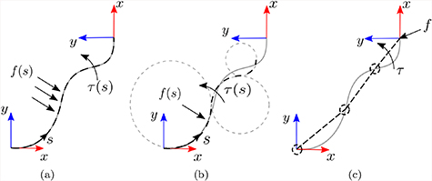
Figure 7. Schematic representation of the three classical modelling approaches of continuum robots (a) Cosserat rod model, (b) piece-wise constant curvature and (c) rigid-link model. f(s) and τ(s) represent the vector fields force and torque with respect to the robot's length (s), respectively.
Download figure:
Standard image High-resolution image
Modelling techniques for continuum robots can be divided into: classical methods (such as Cosserat rod theory [71], constant curvature [73], rigid link models [229, 234]); combined methods [117, 196, 230, 233, 235]; and emerging techniques [228, 236].
5.2.1. Classical methods
The classical methods applied to modelling of continuum robots can be subdivided in terms of strictness of their assumptions. In particular, Cosserat rod theory aims at solving the static equilibrium of the manipulator fully (figure 7(a)) without simplifying assumptions; (piece-wise) constant curvature modelling assumes the robot shape fits the arc of one or more circles (figure 7(b)); and rigid-link assumption would subdivide the robot into (infinitesimal) rigid links (figure 7(c)). These techniques listed with increasing strictness of assumption and consequent ease in description lead to relative pros and cons, described in the following.
Cosserat rod theory
Cosserat rod theory does not undergo specific assumptions and is, therefore, an exact solution to the statics of the continuum robot (see figure 7(a)). This approach consists of solving a set of equilibrium equations between the position, orientation, internal force and internal torque of the robot [117].
Despite the exact solution given, it suffers from drawbacks that prohibit wide use. There are difficulties in extending to dynamics since it would involve the solution of a system of partial differential equations [237]. Moreover, the solution of this approach is to be computed numerically, leading to high complexity and computational expense and a lack of a closed-form solution.
Constant curvature
Constant curvature models are based on the assumption that the continuum robot deflects as arcs of a circle, as represented in figure 7(b). This constitutes a significant simplification when compared to Cosserat Rod and leads to possible analytical solutions for kinematics [235], statics [232] and dynamics [231]. In figure 7(b), we represent piece-wise constant curvature modelling, i.e. the robot is modelled as a series of links that can deflect with constant curvature. Assuming constant curvature only, even if widely used, is more restrictive.
Even if piece-wise constant curvature modelling may constitute a valuable trade-off between the complications of Cosserat rod theory and the assumptions of rigid-link models, most of the literature has focused on the single constant curvature [231, 235] without exploiting the larger generalization provided by combining constant curvature segments [232, 238]. This would be of great value, especially due to the possible extension to dynamic modelling [231] and the reduction of numerical intensity with respect to rigid-link approaches.
As underlined in figure 7(b), one of the drawbacks may be constituted by the lack of compliance to the constant curvature assumption with possible consequent deviation from the real robot's behaviour. Extension to the polynomial curvature case has also been recently proposed [239]. However, further experimental analysis and discussion of its application is needed.
Rigid-link model
Assuming a continuum robot can be divided into (small enough) segments [229, 234], behaving as rigid links (see figure 7(c)), is a significant assumption when dealing with continuum structures. This would either lead to behaviours which are far from reality (few segments) or a very large number of variables (many segments). Employing the rigid-link assumption is a useful simplification since it permits the use of well-established approaches for control and sensing [224].
In the presence of sensing [234] (see section 5.4), the simplifications related to the usage of this model may be mitigated and compensated by the measure of the robot's behaviour. Therefore, the designer may find a balance between model and sensing complexity to find an optimal approach.
5.2.2. Combined methods
Due to the continuously emerging design, fabrication and actuation methods for CMs, single model approaches are of limited use. In fact, depending on the type of actuation, models need to be a combination of the intrinsic robot's behaviour and actuation dynamics. In this case, the wrench we previously defined as extrinsic becomes an integrated module of the robot's model.
Large interest since the early days of continuum robotics has been paid to backbone continuum robots [117, 230, 233, 234, 240] (see section 4.1). Due to the contact between cables and discs, several authors have combined friction models with discs dynamic model [233, 240]; and with the constant curvature model [230].
In the last few years, interest towards magnetically actuated catheters has soared [196, 227, 229]. Here an extrinsic wrench is generated as a consequence of the interaction between internal magnetised agents. In general, the considered models are a combination of the dipole model [50, 241] with rigid-link model [229] or with Cosserat rod model [196, 227]. As far as the authors are aware, combinations with piece-wise constant curvature models have not yet been investigated; although, they may be promising, owing to the possible existence of an analytical solution to the combination of dipole model and constant curvature model.
5.2.3. Emerging techniques
The previously described modelling approaches, given the very novel nature of continuum robots, are not without drawbacks. Therefore, new paradigms for modelling continuum robots have recently been investigated.
In particular, in [236] the authors attempt to overcome the limitations of constant curvature modelling by substituting circular curves with Euler curves which proved to be a better fit for a pneumatic continuum robot. In [228], the authors employ a quasi-static approach based on optimal configurations taking inspiration from optimal non-linear control. Despite the promising results, the lack of analytical solution and the difficulties in generalising the dynamic modelling are the main drawbacks of this approach.
Even if, intuitively, research should be driven by the quest for more and more accurate modelling approaches, accuracy is generally paid for with computational burden. This expense, given the interest towards models for real-time control over simulation for design, is a fundamental parameter to consider in the choice and/or investigation of a modelling approach. Moreover, control is generally based on both model and sensors (see section 5.4) and the aim of the designer is the balance between these two components. Therefore, we expect research to evolve towards more affine-to-control modelling approaches [238, 239] with the mindset of complexity mitigation.
5.3. Control
Control is one of the fundamental aspects of any robotic platform since it gives significance to the mechanical properties of any autonomous system. Interestingly though, only 9% of researchers seem to be focused on this topic within soft continuum robots [225]. This could be interpreted both as a consequence of the large interest in other aspects of CRs, such as mechanical design, or equally related to the very limited knowledge in terms of modelling (see section 5.2) and sensing (see section 5.4). In fact, to achieve accurate control, both these aspects are fundamental, even though the presence of a human-in-the-loop - as found in medical robotics - may mitigate some shortcomings [78].
The lack of accurate or appropriate sensing mechanisms in certain situations has led researchers to differentiate between open loop, which is based on model inversion; closed loop based on feedback of the robot's actuator; and feed-forward and feedback combined control [225]. Despite the effectiveness of this partition, the last two classes can be grouped more generally within the closed loop control class [242] with their differences related to being model-based and model-free.
Control in continuum robots can be divided into: kinematic and differential kinematic control [243–246]; adaptive and learning-based approaches [247–254]; and wrench-based controllers [227, 255–260].
5.3.1. Kinematic approaches
Kinematic approaches include any controller that considers the inverse kinematics or inverse differential kinematics, under the clear assumption that any controller needs knowledge of the direct kinematics. The application of inverse kinematics is the most widely used approach to controlling robots and considered straightforward for standard robots [261]. Due to the highly redundant design of continuum robots, inverse kinematics is not particularly effective [243]. In fact, kinematics is generally not bijective for redundant manipulators and infinite solutions exist for the inverse kinematics [224]. Nevertheless, a large amount of research has recently focused on learning inverse kinematics.
Differential kinematics [245], on the other hand, is particularly effective with redundant manipulators, since it allows multi-task control [225]. A good example of such cases is the dual-arm concentric tube coordinated control [244]. Assuming the differential kinematics to be known with sufficient accuracy can be a relatively strong assumption given the modelling approximations designers are forced into. Satisfactory accuracy might not therefore be assured. To overcome this limitation, adaptive approaches have been proved effective in some scenarios.
5.3.2. Adaptive and learning approaches
To deal with partial knowledge of the robots (differential) kinematics, some authors have started investigating adaptive and learning approaches, which are aimed at compensating for modelling approximations with data gathering. These approaches can be subdivided into mechanical adaptation methods and learning-based methods. The former are generally based on some approximated mathematical model for the manipulator and aim at real-time adaptation of the approximations; the latter are data-driven modelling approaches.
Adaptive approach
This approach is generally applied to approximated models, whose inaccuracies can be mitigated by the presence of a feedback loop. The problem is tackled as the estimation of the mechanical parameters is done on-line. In particular, the approach in [253] describes the robot's pose as a Fourier series expansion and a recursive least square approach is applied to update the parameters. More satisfactory results were found by applying a locally weighted projection regression, by approximating the model with a collection of linear models and adaptation performed by means of a stochastic gradient descent approach [254].
A different approach has been recently presented in [252], with the application of a model-free adaptive controller based on visual servoing. Another approach considers the adaptive observer of a Kalman filter [251], designed to estimate the Jacobian matrix of the manipulator. However, the model of state evolution is relatively simple and does not consider the mathematical properties of the Jacobian matrix.
Learning approach
More recently, modelling and control based on machine learning methodologies has gained much interest amongst the robotics community. These methods, as with the previously mentioned adaptive counterpart, have the common aim of avoiding complex and approximated analytical models. In particular, contrived mechanical response models can be replaced with data-driven model-free simulations. Examples of such strategies appear in [247] which uses a multilayer perceptron with a single hidden layer, the multilayer network employed in [176, 248] and a modified Elman neural network and Gaussian mixture model in [250]. Despite some promising results and the recent surge in the application of learning techniques to robotics, a limitation of these methods is the blindness to real mechanical interactions. This lack of physical significance endorses a lack of underlying physical comprehension, this in turn can produce an un-auditable system and may lead to potentially hazardous undetected inaccuracies.
5.3.3. Wrench-based approaches
Since the actuation of a continuum robot can be generally related to the interaction between their flexible structure and actuating (external) wrenches (see section 5.2 for more details), some authors have tackled the control problem by directly controlling the actuating wrench. Some examples are the static approaches in [227, 256, 259] and dynamic approaches in [260].
As an outcome of this vision, due to the redundant nature of continuum robots, compliance/stiffness [255, 259] and task-space force [256] control have been investigated. This is of primary importance for some medical robotics tasks, such as smooth navigation in soft environments and palpation [258]. Nevertheless, the estimation of a robot's force is not trivial without the assistance of sensors. Therefore, [117] and [258] have independently worked on the estimation of the force by applying a probabilistic and deterministic approach, respectively.
Literature on control of CMs shows significant interest in model-based approaches. Given the complex mechanical behaviour of CMs and the need for several diverse and interconnected elements (see section 5.1) in their design, mechanical characterization may lack accuracy and thus induce errors in control. We therefore envisage that other methods, such as adaptive methods or deep learning, will be implemented to compensate for this drawback.
5.4. Sensing
As stated previously, accurately modelling CMs remains a huge challenge, reinforcing the need to further develop techniques to improve controllability, actuation and safety. Real-time shape sensing of CMs allows for more precise and reliable motion control. To date there are three main types of shape sensing employed in CMs: optical sensing, electromagnetic tracking and imaging techniques.
5.4.1. Optical based shape sensing
Optical sensing is based on the use of fibre Bragg grating (FBG) sensors written onto optical fibres. These are able to reflect a narrow range of the full spectrum of input light depending on the fibre's strain and temperature [262]. This way, by incorporating several FBG sensors along an optical fibre it is possible to estimate the shape given the strain measurements at each sensor. Consequently, embedding one or more optical fibres with FBGs in CMs enables shape sensing of the device.
The popularity of this method has been increasing in continuum structures, especially those which undergo small deflections. Needles are one of the most common structures where this sensing method has been employed. Needles are inherently stiff, supporting a nearly perfect strain transfer to the attached FBGs. Three optical fibres with two FBGs each have been reported to give very accurate results for single 2D deflections [263]. However, as the deflection complexity increases to double deflections [264], or 3D deflections [262], the inaccuracy increases significantly. The main sources of errors have been attributed to a low number of sensors and their inaccurate placement during fabrication. Additionally, the location of the FBGs has also been reported to have a fundamental role [263, 264].
This sensing technique has also been used on less stiff structures such as catheters [265–267] and endoscopes [268, 269]. These structures are more challenging due to the lower strain transfers onto the sensors. In fact, preliminary work on the field was not able to achieve accurate results [268] or had to be used in combination with other sensing techniques [266] such as those reviewed here. Recently 3D shape reconstruction of catheters was achieved using multi-core fibres [267].
Overall, using FBGs sensors for shape sensing of CMs is a viable solution, especially for structures that undergo small deflections. Furthermore, its usage on force and torsion sensing has also been demonstrated, allowing higher sensing capabilities without the need of extra equipment [270–273]. Its insensitivity to magnetic fields allows its usage in a variety of medical situations such as MRI or coupled to magnetically actuated devices. Nevertheless, the technology still faces significant challenges that hinder its mainstream use, especially in high deflection structures. Not only will the sensors give less accurate results due to a lower strain transfer ratio but they will also damage easily when subjected to such strains. This imposes strict limitations to the devices that are suitable for this type of shape sensing. Additionally, the relatively high cost of such technology hinders its application in low cost devices. The number of sensors and their placement are also shown to have a major impact on results [274, 275].
5.4.2. Electromagnetic tracking based shape reconstruction
Electromagnetic (EM) tracking uses mutual induction between a magnetic field generator and a magnetic field sensor for shape reconstruction. Two variations of this method have been proposed based on the location of the magnetic field generator, either external or internal to the robot.
External methods are the most common and use commercially available EM tracking systems, such as the NDI Aurora [276], for shape reconstruction. These systems are able to determine the pose of small sensors on a generated external magnetic field. By placing these sensors along the robot, the system is able to determine the robot's pose. The usage of these systems for shape sensing has been widely demonstrated [277, 278] and methods to estimate contact force have also been reported [279, 280]. Despite its promising results, this method is constrained by the limitations of the localisation method itself, such as limited workspace and variable accuracy within it [278].
Internal methods are able to overcome these limitations by placing the source of the magnetic field inside the robot itself. Two small permanent magnets alternated with two Hall effect sensors along a CM were able to reconstruct 2D shape [281]. By measuring the magnetic field at the location of the Hall effect sensors, it is possible to estimate the relative position and therefore, the deflection of the manipulator. Similar approaches have been reported [282–284] and a common limitation to them all is that with increasing deflections, the errors increase. This is due to cross talk between the sensors and the magnets, posing limitations to minimum bending radii.
Electromagnetic tracking shape sensing methods are able to provide freedom from line-of-sight restrictions and are relatively easy to incorporate into the robot. However, they are highly susceptible to magnetic disturbances from nearby equipment. External methods using commercially available systems cannot be used in conjunction with magnetically actuated robots or MRI applications [285]. Nonetheless, proprietary localisation methods could be developed for the specific application and robot, such as [49]. Internal methods suffer from crosstalk between sensors and magnetic agents during high deformations, hindering the reliability of shape estimation results. Furthermore, the incorporation of an internal magnetic field generator can impose limitations on the robot's size. Nevertheless, assuming these challenges are addressed, this method could potentially achieve much smaller bending radii than FBG, facilitating its use in soft CRs.
5.4.3. Imaging based shape estimation
Imaging methods rely on current medical imaging techniques to track and estimate the shape of CMs. Unlike the previous methods, this approach does not required the integration of any additional sensors onto the surgical instrument which can be beneficial from a design and miniaturisation point of view.
Fluoroscopy [268, 286, 287] and ultrasound [287, 288] are the two main imaging techniques used in shape estimation of CMs and endoscopes. The usage of biplane fluoroscopy for shape estimation of continuum structures has been reported and is known to achieve accurate 3D reconstructions [165, 289]. However, these methods depend on biplane systems that are associated with large radiation dosages and costs. Given the nature of monoplane fluoroscopy, detecting out of plane deflection using imaging alone is not possible [290]. Several works have combined planar imaging techniques with tracking methods [290–292] or kinematic modelling [293, 294] however these systems tend to achieve less accurate results. Shape estimation of CMs using endoscopic cameras has also been reported and is generally performed on a marker-based or markerless approach [295, 296]. Marker-based approaches require additional integration of components into the device, while markerless require large manually labelled training sets [296]. Furthermore, these methods are normally limited by the field of view of the camera.
Imaging based methods can provide reliable results for shape sensing of CMs. There are no limitations to the minimum bending radii these methods can potentially achieve, unlike alternatives methods which, for larger deflections, can become erroneous. They are limited of course by image resolution, noise and processing techniques. Furthermore, due to their dependency on and need for integration with, hospital equipment, they may not be readily implemented.
In summary, recent developments in shape sensing for CMs has improved their efficacy. However, when introducing additional on-board hardware, as in FBG and EM tracking approaches, robot miniaturisation, stiffness, flexibility and durability can be adversely influenced. Off-board sensing methods remove such restrictions and of these, imaging-based methods are most prevalent, offering potentially practicable solutions to the sensing problem if suitable clinical integration can be realised. A less explored but promising off-board approach employs load cell sensors located at the robots proximal end for estimation of tip force and shape [297, 298]. Ultimately, the limited accuracy of flexible and soft robots, particularly when subject to interaction forces, hinders their reliability in clinical settings. Methods for shape sensing are therefore essential to realise the full potential of medical CRs and future development may engender ever smaller bending radii measurement, while maintaining high accuracy and miniaturisation capabilities.
6. Conclusions and future directions
Medical robotics has seen remarkable innovation over the last decades. Driven by the need for less invasive procedures while maintaining dexterity levels, continuum robots have established themselves as a viable alternative to traditional rigid-link manipulators. The recent commercial releases of continuum platforms for robot-assisted procedures further advocate their future place in advanced healthcare practices.
Despite the progress achieved, further advancements are highly dependent on current challenges across actuation, fabrication, control and sensing. As with traditional surgical robotic systems, continuum robots are commonly intrinsically actuated using tendons or pressurised fluids, limiting the achievable DOF as their size reduces. External actuation via magnetic fields does not suffer from this scaling issue, providing a promising approach for controlling continuum robotic devices, especially at the small scales required for medical applications. Magnetic soft robots may provide an optimal solution as they are able to combine the freedom in scale from magnetism with the safe interaction of soft robots.
Fabrication and control of such devices is currently still a challenge given the materials employed and the magnetisation patterns needed for actuation. However, allied to these challenges is also the possibility for major breakthroughs. Developments in digitally-driven and computer controlled manufacturing processes holds potential to allow an exciting next generation of continuum robots, with greater resolution and dexterity, enabling us to reach and treat areas of the human anatomy that may otherwise be inaccessible.