


Abstract
Low-toxicity solar concentrator systems represent an important challenge for outstanding photovoltaic (PV) applications. Particularly, multiplexed holographic lenses (MHL) as Holographic Solar Concentrators (HSC) provide insight into promising possibilities for Building-Integrated Concentrating PVs. This technology does not affect crucial ecosystems, and can convert buildings from energy consumers into energy suppliers. They can be used in windows, roofs, or walls, and a high diffraction efficiency and wide acceptance angle are desired. In this work, we presented several designs of MHL of low spatial frequency 525 lines mm−1, based on a low-toxicity photopolymer and supported on a window glass. The average diffraction efficiency of these HSC was evaluated at 633 nm, whereas the acceptance angle was evaluated by measuring the short-circuit current under solar illumination at different incident angles. Versatile and high-efficiency holographic elements have been used to concentrate sunlight from different relative positions during the day, avoiding the need for expensive tracking systems. To the best of our knowledge, this is the best trade-off between high diffraction efficiency (85 ) and wide acceptance angle (104∘) in a low-toxicity holographic solar concentrator.
Export citation and abstract BibTeX RIS

Original content from this work may be used under the terms of the Creative Commons Attribution 4.0 license. Any further distribution of this work must maintain attribution to the author(s) and the title of the work, journal citation and DOI.
Abbreviations
| HL | holographic lens |
| RL | refractive lens |
| MHL | multiplexed holographic lenses |
MHL
| number of multiplexed holographic lenses |
| HSC | holographic solar concentrator |
| PV | photovoltaic |
| PVA | polyvinyl alcohol |
| NaAO | sodium acrylate |
| NaOH | sodium hydroxide |
| HAO | acrylic acid |
| TEA | triethanolamine |
| RF | riboflavin 5'-monophosphate sodium salt |
1. Introduction
Today, concentrating PV technology is increasingly recognized as the most promising technology to meet the world's energy challenges. Nowadays, an increasing number of buildings are incorporating solar panels on their facades by integrating solar concentrators into parts of buildings, such as windows, roofs, or walls [1]. However, solar PV power plants prevent the use of agricultural land and may affect crucial ecosystems [2]. Solar panels that are placed on large tracts of land have a very large surface area and often use solar trackers that require electrical power input (which consumes resources), must be anchored to the ground, and the structure is usually not cheap. Another drawback of solar trackers is that their moving parts break down over time and require periodic maintenance. Moreover, a classic disadvantage of this technology is the high-cost of photocell production.
The first design of an experimental PV concentrator module was published in 1984 at the Sandia Laboratory in New Mexico (USA)[3]. Since then, innovative and high-efficiency solar cell designs have been demonstrated, but their price still motivates the development of PV concentrators that allow the reduction of solar surface area [4]. Commercial PV concentrator systems usually employ Fresnel lenses [5–7] or parabolic mirrors [8]. Fresnel lenses are flat, lightweight lenses with concentric grooves that focus or collimate light and, like traditional lenses, work by refraction and therefore have small acceptance angles (around 2.5∘). Parabolic mirrors, on the other hand, are curved parabolically-shaped reflecting surfaces that focus incoming light onto a single point. They are used as solar concentrators for both PV and thermal energy and have larger acceptance angles than Fresnel lenses (around 30∘–35∘). The acceptance angle is defined as the maximum angle at which incoming sunlight can be captured by a solar concentrator. Maximizing the acceptance angle of the concentrator is desirable in practical systems and it can be achieved by using non-imaging optics with solar tracker systems. Solar trackers follow the Sun's trajectory [9], allowing direct sunlight to be concentrated from sunrise to sunset.
As a future challenge in this field to reduce the levelized cost of energy in solar concentrator systems, it is important to develop maintanence-free, light-weight, low-cost, and low-toxicity systems. Holographic optical elements obtained using the holographic technique can be an alternative to conventional lenses because they are cheaper, lighter, and more versatile than Fresnel lenses or parabolic mirrors. They provide an enlarged focusing area that helps protect solar cells from heating damage [10] and can also increase the conversion efficiency in solar concentrating systems by using different band-gap PV cells, such as indium gallium phosphide cells combined with silicon cells [11]. Therefore, HSC have great potential to diffract light at large offset angles and offer great possibilities for multiplexing a large number of optical elements in the same device [12, 13].
The first holographic optical element as a solar concentrator was proposed by Ludman in 1982 [14]. In the following years, several designs of HOEs were published [15–18]. During the last few years, HOEs have been widely proposed as solar concentrators. Researchers have described high [19] and low [20, 21] spatial frequency holographic concentrators with operating angles from 12∘ to 30∘. Different types of holographic lenses, spherical [19, 21] and cylindrical [11, 21, 22], have also been developed for solar applications, operating under high and low photometric conditions. Kostuk et al described the characteristics of transmission and reflection holographic elements for solar-concentration applications [23, 24]. In this work, we focus on volume-transmission holographic optical concentrators for outstanding PV applications. Holographic volume elements allow controlling the solar radiation that impinges on the photocell based on its spectral range and incident angles (chromatic and angular selectivity), avoiding harmful radiation that can deteriorate photocells and which does not efficiently convert solar energy into electrical energy.
On the one hand, acceptance angles of up to around 35∘ HSC have been developed using angular multiplexing holographic optical elements [25] and hybrid PV systems for direct and diffuse light [11]. On the other hand, high diffraction efficiency HSCs have been obtained using different designs [11, 21, 26]. Vorndran et al produced a spectrum-splitting PV module in 2016 that used an array of two off-axis volume holographic lenses (20 µm thick and 2 cm focal length), which achieved  diffraction efficiency and 38∘ acceptance angle, but based on dichromated gelatin [11]. Akbari et al proposed, one year later, an array of two HOEs prepared on an acrylamide-based photopolymer with 50 µm thick and a focal length between 3 and 10 cm. This design presents a high efficiency of approximately 95
 at 633 nm, but a 12∘ acceptance angle [21]. The only commercial prototype of the holographic concentrator was designed by Prism Solar Company [27]. This system consists of multiple transmission holograms multiplexed on dichromated gelatins.
One of the most important aspects of these optical systems is the material used to fabricate them. Both dichromated gelatin and photopolymers are excellent holographic materials with the ability to modulate their refractive index with high resolution, high diffraction efficiency, and low scattering. Dichromated gelatin is a holographic material with two main drawbacks: it requires chemical post-processing and one of its compounds, chromium, is poisonous [28, 29]. Photopolymers are the most manageable holographic materials, which can be modified for both composition and design. Other interesting properties include variable thickness, flexibility, self-processing capability, high-energy sensitivity, good dimensional stability, and low-cost. The importance of photopolymers has grown tremendously, and diverse photopolymer materials have been widely used in optical applications. There is also a commercial photopolymer, Bayfol HX, that is widely used in holographic applications [19, 22]. However, one of the common components on holographic photopolymers is acrylamide [21], which is a toxic and carcinogenic compound [30].
The latest trends in holographic materials include environmentally friendly photopolymers with good recycling properties and low-toxicity. Biophotopol, a low-toxicity photopolymer, meets all these requirements for recording holographic optical elements [31–35]. It can contribute to the development of sustainable energy systems. In 2022, Morales et al published the first HSC in Biophotopol with 60∘ acceptance angle and  average diffraction efficiency [36].
In this study, we present an HSC with a wide acceptance angle of 104∘ and at the same time a high diffraction efficiency of  . HSC is formed by five MHLs that have been recorded in Biophotopol with different parameters, such as the number of multiplexed elements, thickness, or angular separation between peaks. Finally, the future prospects of this work for breakthrough PV applications are discussed.
2. Methods
2.1. Photopolymer preparation
The researchers recorded volume phase transmission MHLs in a photosensitive Biophotopol photopolymer, which is a low toxicity material that contains one or more monomers in a binder, an electron donor, and a dye sensitizer. They prepared the Biophotopol composition using various compounds including NaAO as a monomer generated in situ, TEA as the initiator and plasticizer, RF as a dye, water as a solvent, and PVA as a binder (hydrolysis grade = 87.7 , Mw = 130 000 g mol−1). Prepolymer solution optimized concentrations were 11.3 w/w
 , 0.49 M, 1.7·10−3 M, and 11.1·10−3 M for PVA, NaAO, RF, and TEA, respectively. The prepolymer solution was deposited in glass moulds
  cm2 and left to dry in the dark inside an incubator for 24 h at a controlled relative humidity of 60 ± 5
 and a temperature of 20 ± 1 ∘C. The drying process was carried out in a controlled light environment to ensure that the photopolymer layer was not sensitive. Photopolymer plates reached equilibrium with the surrounding environment during the drying period by water evaporation. Layers from 100 to 204 µm thick were prepared for holographic recording from different prepolymer solution volume.
2.2. Recording setup
The experimental setup utilized for recording involved a diode-pumped laser emitting continuously at 473 nm, which was spatially filtered and then split into two secondary beams (one for object and one for reference) using a 1:1 beam splitter cube. The recording intensity of the setup was 2.2 mW cm−2. A collimated reference beam and a divergent object beam were directed onto the photopolymer, creating an interference pattern. The divergent beam was generated by a RL with a dioptric power of 20 D at a distance of 2  (10 cm) from the photopolymer surface in order to obtain an identical spot size. Figure 1 provides a visual representation of the experimental setup used during the recording stage. In addition, to optimize the exposures of each of the multiplexed holograms, an unexpanded He–Ne laser emitting at a wavelength of λc = 633 nm was used as the control, at which the recording material was not sensitive (monitoring stage).

Figure 1. Holographic recording process and setup. M: mirror, RL: refractive lens, ES: electronic shutter, SF: spatial filter, BS: beam splitter, PC: computer.
Download figure:
Standard image High-resolution imageThe experiment involved measuring the object and reference recording angles (θo and  ) with respect to the MHL normal, where positive angles were measured clockwise and negative angles were measured counterclockwise. The two beams were overlapped in the photopolymer layer, and the inter-beam angle (
 ) was set at 14.5∘ for all recorded holograms. This resulted in a low central spatial frequency (525 lines/mm) and a grating period (Λ) of 1.907 µm, which was calculated using the Bragg equation (1),
where λ is the wavelength of vacuum. The sample was rotated around its vertical axis to record peristrophic multiplexed holograms (MHLs) [12]. Therefore, different object θo and reference angles θr were used in each exposure depending on the desired holographic concentrator.
Figure 1 shows the storage of the interferential pattern in the recording material. The object and reference beams impinge on the material, and the monomer exposed to the light changes its refractive index and transforms into a polymer, whereby polymerization and diffusion processes occur, and finally, the interferential pattern information is stored.
2.3. Reconstruction setup
After the recording stage and before the reconstruction stage, we exposed the recorded photopolymer layer to a 13.5 W (875 lumens at 6500 K, Lexman) LED bulb, which was positioned 37.5 cm from the sample, for 15 minutes. This step served to polymerize any residual monomer and remove any remaining dye from the sample [37]. The curing process is illustrated in figure 2(A). The physical thickness of the photopolymer layers was measured using a micrometer screw at the end of the experiment.
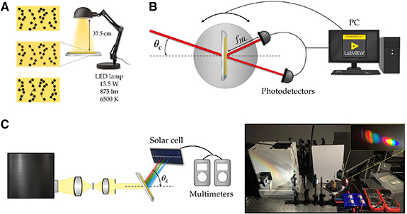
Figure 2. (A) White light curing process with a LED lamp. (B) Reconstruction setup using a He–Ne laser.  : focal length of the holographic lens, θc: reconstruction or conjugate angle, PC: computer. (C) Holographic solar concentrator setup and image of the real setup (See supplementary video file 1).
Download figure:
Standard image High-resolution imageTwo experimental setups were used to reconstruct MHLs. Because the bandgap of silicon solar cells is obtained for the infrared band (1100 nm), it was decided to reconstruct the MHLs using a He–Ne laser emitting at 633 nm with an intensity of 5 mW cm−2. This was because these cells respond better at 633 nm than at 473 nm because they are closer to the bandgap zone. The experimental setup used for the He–Ne laser reconstruction is shown in figure 2(B). The same setup was used for monitoring the HL recording stage. The reconstruction angle was calculated using equation (1) to be  . It is important to note that because negative holographic lenses were recorded, the reconstruction had to be performed with at conjugated beam, that is, rotating the hologram 180∘ and impinging on the part where the glass was.
The experimental setup used to reconstruct the MHLs using a solar simulator is shown in figure 2(C). MHLs used in the experiment were characterized by a broadband unpolarized source and a monocrystalline silicon PV cell (PHYWE  cm2). The relative value of the short-circuit current under short-circuit conditions (
 ) was measured. A standard solar simulator source (model 10 500, ABET Technologies) was used to emit a continuous solar spectrum (350–1800 nm), which was collimated to reconstruct the holographic lenses by the convergent conjugated beam to obtain the real image. The diffracted beam of the holographic lenses focused light on the PV cell as an extended focus. However, the chromatic dispersion of the diffracted beam produced an aberrated image on the surface of the solar cell. This is because each wavelength diffracts at a given image angle and focal length. The calculation of these parameters is given by equations (2) and (3) [38, 39], respectively:


where θ is the off-axis angle; R denotes the distance of the respective beams; and i, c, o, r are the subscripts of the image, reconstruction, object, and reference beams, respectively. Considering that the reference and reconstruction beams are plane waves, Rr
and Rc
tend to infinity and Ro
is the refractive focal length. In addition,  is the focal length of each lens, and µ is the ratio of the reconstruction wavelength to the recording wavelength,
  .
.
The design of solar concentrators requires the optimization of two fundamental parameters: the diffraction efficiency (η) and acceptance angle ( . The first parameter refers to the amount of light the concentrator can diffract toward the solar cell, and the second parameter refers to the angular range in which the concentrator can diffract light.
Diffraction efficiency describes the amount of optical power diffracted by a hologram at a desired wavefront. It is defined as the power diffracted in one or more diffraction orders relative to the power incident on the hologram,

where ED
and PD
are the diffracted irradiance and the diffracted optical power at the ith order, respectively, and  and
and  are the total irradiance and the total power incident on the hologram, which in this case has been taken to be the transmitted power plus the diffracted power. For the theoretical fit of the diffraction efficiency, the analytical solution obtained by Kogelnik's Coupled Wave Analysis (KCWA) [40] was represented (equation (5)). This theory predicts the diffraction efficiency at a particular λc around the Bragg angle for a transmission phase grating with a thickness (d),
In equation (6), the variable ξ changes in relation to the detuning parameter (ϑ), as indicated in equation (7), which is contingent upon Λ (grating period), θc (reconstruction angle),  (reconstruction angle inside the material), λc
(reconstruction wavelength), ϕ (slope of the fringes), and n (refractive index).ξ assumes a value of zero when the system is in the Bragg condition, while it becomes either positive or negative when the system is operating outside the Bragg condition. The lenses have been fitted considering only the central value of K (grating vector) due to its small diameter,
(reconstruction angle inside the material), λc
(reconstruction wavelength), ϕ (slope of the fringes), and n (refractive index).ξ assumes a value of zero when the system is in the Bragg condition, while it becomes either positive or negative when the system is operating outside the Bragg condition. The lenses have been fitted considering only the central value of K (grating vector) due to its small diameter,

The dynamic range and the average diffraction efficiency were calculated to determine the diffraction efficiency of each of the MHLs [41]. The dynamic range is defined as the number of holograms with diffraction efficiency η = 1 (100 ) that can be stored in a material with a given thickness. Its mathematical expression is given by:
where ηi is the diffraction efficiency of each hologram, and N the number of recorded holograms. To calculate the dynamic range, we must sum the square roots of the diffraction efficiencies of all holograms that have been recorded in the material. From the dynamic range, it is possible to determine the number of holograms that can be stored in the material to obtain a certain diffraction efficiency, or alternatively the average diffraction efficiency for a given number of stored holograms. The latter average diffraction efficiency is given by
While the diffraction efficiency η is a parameter defined when reconstructing with a given wavelength, the acceptance angle θacc was defined for reconstructions with the solar simulator, because the solar cell collects all diffracted wavelengths. To perform this measurement, the angular width was determined for a specified current value of 0.02 mA. This value was taken as the criterion for comparison.
3. Results
HSC consist of MHL capable of focusing diffracted light onto the solar cell area. Figure 3 shows an example of different types of HSCs. Figures 3(A) and (B) show the reconstruction with a He–Ne laser (633 nm) and a solar simulator, respectively, for a concentrator based on a single HL recorded in a layer of 100 µm physical thickness. It can be seen that while the diffraction efficiency is higher (92 ), the angular range for which it works is narrow (
 ). On the other hand, figures 3(C) and (D) show a solar concentrator based on the multiplexing of two holographic lenses (MHL2) with the same physical thickness. In this case, it is observed that although the average diffraction efficiency is a slightly lower (
 ), the acceptance angle is larger (
 ). In addition, figures 3(A) and (C) have been fitted using the KCWA. The theoretical parameters of the fit obtained are
  ,
,  m (figure 3(A)) and
  ,
,  m (figure 3(C) first peak, black line), and
  ,
,  m (figure 3(C) second peak, blue line). Therefore, it is important to determine an agreement between the diffraction efficiency and the acceptance angle for the design of optimal solar concentrators. The parameters involved in this optimization are the number of multiplexed holograms, photopolymer layer thickness, and angular distance between peaks. In this work, a study of the relationship between these parameters was conducted.

Figure 3. Diffraction efficiency (η) vs reconstruction angle (θc) with a He–Ne laser (633 nm) (red dots) and KCWA fit (black and blue lines): (A) and (C), short-circuit current vs reconstruction angle (θc) with the solar simulator: (B) and (D) for HSC based on HL: (A) and (B), and for HSC based on MHL2: (C) and (D).
Download figure:
Standard image High-resolution imageFirst, this study was conducted to determine the optimal number of MHLs. For this purpose, the acceptance angle and diffraction efficiency (figure 4(A)) were studied as the number of multiplexed holograms increased. The cases studied were 1, 3, 5, 7, 9, and 11 MHL with a constant angular separation between peaks (7.25∘) and a constant physical thickness (approximately 150 µm). The acceptance angle increased as the number of holograms increased, but the diffraction efficiency decreased. Therefore, it is important to find an agreement between an acceptable angle and a good diffraction efficiency. From figure 4(A), it can be observed that for MHL5, a good agreement between both parameters was obtained because an average diffraction efficiency of approximately 60 and an acceptance angle of approximately 45∘ were obtained.
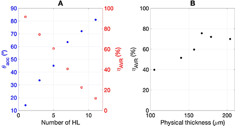
Figure 4. (A) Acceptance angle (θacc) vs number of multiplexed holographic lenses (filled blue circles). Average diffraction efficiency (ηAVR) vs the number of multiplexed holographic lenses (empty red squares). (B) Average diffraction efficiency (ηAVR) vs physical thickness.
Download figure:
Standard image High-resolution imageAfter analyzing the optimal number of holograms as a function of the acceptance angle and diffraction efficiency, we decided to study HSCs based on the multiplexing of five holographic lenses (MHL5). To optimize the conditions for obtaining high-efficiency MHL5 while maintaining the angular spacing between peaks, the thickness of the photopolymer layer was analyzed in an attempt to record five holographic lenses with all diffraction peaks with the highest possible efficiency. Firstly, the study commenced by examining 100 µm layers for 1 and 2 HLs. Nevertheless, the thickness of the photopolymer layers was subsequently increased to enable the multiplexing of additional lenses, achieving higher average diffraction efficiencies. Layers with ticknesses of 105, 140, 157, 167, 179 and 204 µm are analyzed in figure 4(B). Between 100–160 µm, the greater the thickness, the higher the average diffraction efficiency. From 170 µm, the average diffraction efficiency seems to stabilize at approximately 70%–75 .
.
Finally, we analyze the manner in which the diffraction efficiency changes as a function of the angular distance between five peaks (MHL). The main aim is to increase the area and optimize the intensity envelope curve when reconstructing the MHL5 with a solar simulator. Three different cases were investigated ( , 5.00∘ and 7.25∘). The parameters used in the recording stage for the optimized MHL5 are listed in table 1. The exposure parameters for recording each of the concentrator's holographic lenses were analyzed and chosen according to real-time analysis at the recording stage. Such analysis was performed for photopolymer layers of approximately 170–180 µm of physical thickness and to adjust all diffraction peaks to the same efficiency. In addition, the recording angles were designed such that the central peak would be at incident angle of 0.00∘ when the reconstruction was performed using the solar simulator.
Table 1. Parameters used in the recording stage for the optimized MHL5.
MHL5
| MHL5
| MHL5
| |||||||||||||
|---|---|---|---|---|---|---|---|---|---|---|---|---|---|---|---|

| 1 | 2 | 3 | 4 | 5 | 1 | 2 | 3 | 4 | 5 | 1 | 2 | 3 | 4 | 5 |
| H (mJ cm−2) | 2.2 | 5.5 | 12.1 | 19.8 | 41.8 | 2.2 | 6.6 | 13.2 | 26.4 | 55 | 2.2 | 6.6 | 15.4 | 31.9 | 67.1 |

| 8.50 | 11.50 | 14.50 | 17.50 | 20.50 | 4.75 | 9.75 | 14.75 | 19.75 | 24.75 | 0.00 | 7.25 | 14.50 | 21.75 | 29.00 |

| 84 | 88 | 88 | 84 | 77 | 92 | 86 | 83.9 | 79 | 69 | 63 | 74 | 83 | 70 | 74 |
The results obtained for the optimized MHL5, as described in table 1 are shown in figure 5. On the one hand, figure 5(A) shows the 633 nm laser reconstructions for the MHL5 with peak-to-peak variance  , and 3.00∘. The dynamic ranges were
  and 4.3, respectively. On the other hand, figure 5(B) shows a comparison of the reconstruction with the solar simulator for the above cases. MHL5 has been achieved with
  and
and  for
for  ,
,  and
and  for
for  , and
, and  and
and  for
for  . It can be seen that as the angular distance between the peaks decreases when reconstructed with the solar simulator, the peaks merge into the same optimized envelope curve. As can be seen, the smaller the angle between the peaks, the higher the diffraction efficiency. To evaluate the energy efficiency collected by the solar cell in each MHL5, the area under the curve in the figure above was obtained. For the
  = 3.00∘ case, 10.07 a.u. has been reached, for the
  = 5.00∘, 10.63 a.u. has been reached and 12.63 a.u. has been obtained for the 7.25∘ separation. It should be noted that although a smaller area is obtained for
  , the difference between them is small, and this parameter can provide an idea of the behavior of the light concentrator. Analyzing the average diffraction efficiencies obtained from the reconstructions with the 633 nm laser, the best results (85
 ) were obtained for MHL5 with
  . In addition, by analyzing the short-circuit current collected by the solar simulator, it can be noted that the highest current is obtained and the peak-to-valley variation is negligible. However, considering the acceptance angles obtained from the reconstructions with the solar simulator it was observed that the best results were obtained for MHL5 with
  . However, in this case, the average diffraction efficiency dropped to 73
 and the peak-to-valley variation was not negligible. Considering all the parameters,
  , ηAVR, θacc, peak-to-valley variation, and area under the curve, it can be considered that the best results are obtained for MHL5 with
  . In any case, the design of the HSC should be chosen according to the final design of the HSC-PV solar cell system required in each system.

Figure 5. Analysis of the variation of angular distance between peaks for MHL5. (A) Diffraction efficiency (η) vs incident reconstruction angle (θc) with the He–Ne laser (633 nm). (B) Short-circuit current vs incident reconstruction angle (θc) with the solar simulator.
Download figure:
Standard image High-resolution image4. Discussion
Table 2 summarizes the HSCs developed by several research groups. HSCs may consist of one or more holograms that can be multiplexed or not in different recording materials.
Table 2. Overview of different holographic solar concentrators.
| Recording material | HSC | Number of holograms |
 /HSC /HSC |
 /Hologram /Hologram |

|

|

|
|---|---|---|---|---|---|---|---|
| Silver halide [42] | 1 HL | 1 | — | — | 33 (633 nm) | — | — |
| Dichromated gelatin [11] | 2 HLs | 2 | 38 | 19 | 85 (532 nm) | — | 20 |
| Bayfol HX200 [25] | 1 MHL3 | 1 | 35 | 35 | 28 (532 nm) | 1.6 | 16 |
| Acrylamide based photopolymer [21] | 2 HLs | 2 | 12 | 6 | 95 (633 nm) | — | 50 |
| Ni ion doped photopolymer [43] | 1 MHL3 | 1 | 20 | 20 | 19 (633 nm) | 1.3 | 130 |
| Bayfol HX200 [26] | 3 multilayers HL | 3 | 9 | 9 | 56 (473–633 nm) | — | 16 (x3) |
| Biophotopol [36] | 1 MHL7 ( 7.40∘) 7.40∘) | 1 | 60 | 60 | 47 (633 nm) | 4.8 | 197 |
| Biophotopol | 2 MHL5 ( 7.25∘) 7.25∘) | 2 | 100 | 50 | 73 (633 nm) | 4.3 | 168 |
| Biophotopol | 3 MHL5 ( 5.00∘) 5.00∘) | 3 | 114 | 38 | 82 (633 nm) | 4.5 | 175 |
| Biophotopol | 4 MHL5 ( 3.00∘) 3.00∘) | 4 | 104 | 26 | 85 (633 nm) | 4.6 | 185 |
Sreebha et al [42] proposed in 2015 holographic lenses fabricated in silver halide using off-axis geometry to be employed in windows. With this material they achieved a diffraction efficiency of 33 at 633 nm. The acceptance angle is not indicated in the reference and the diffraction efficiency is low. Vorndran et al [11] in 2016 fabricated a spectrum-splitter PV module composed of two gelatin-based dichromated holographic lenses obtaining an acceptance angle of 38∘ and an average diffraction efficiency over the entire aperture around 85
 . The acceptance angle of each HL was 19∘. It should be noted that dichromated gelatin is considered a toxic material, so it is important to avoid its use [28, 29]. Lee et al [25] designed in 2016 an HSC based on three MHL (MHL3) on Bayfol HX200, a low-thickness material (16 µm). The average diffraction efficiency at 532 nm was 28
 , and the acceptance angle was 35∘. As mentioned above, Bayfol HX200 material is a commercial material whose composition is unknown. The specific formulation and composition of the Bayfol HX200 material have not been published. However, the technical data sheet recommends being careful with its handling and avoiding direct contact with the skin. Akbari et al [20, 21] proposed in 2017 a system based on two HLs fabricated on 50 µm thickness acrylamide-based photopolymer with a diffraction efficiency at 633 nm around 95
 but an average acceptance angle of 12∘. The acceptance angle of this HSC is low and the holographic material is based on acrylamide which, as mentioned above, is a toxic material [30]. Aswathy et al [43] obtained in 2018 holographic concentrators based on three holographic lenses recorded in a photopolymer material doped with nickel ions with diffraction efficiencies of
  ,
,  and
and  , respectively. The average diffraction efficiency was
  and the acceptance angle was 20∘. In this case, the photopolymer is also based in acrylamide, a toxic material. In 2020, Wang et al [26] achieved an HSC consisting of 3 HLs stuck as a multilayer, using Bayfol HX200 material. Notice that each of the HLs was recorded at different wavelengths, namely, 473, 532, and 639 nm, respectively. The acceptance angles for each HL were approximately 9∘. Regarding the diffraction efficiencies, they obtained
  at 473 nm,
  at 532 nm, and
  at 639 nm. Thus, the average diffraction efficiency of the HSC was
  .
.
Taking into account HSCs can be integrated into buildings, it is important to manufacture them in low-toxicity materials. In 2022, Morales-Vidal et al [36] fabricated on Biophotopol (197 µm layers) an HSC formed by one hologram with 7 MHL (MHL7). The acceptance angle was 60∘, but the average diffraction efficiency reached at 633 nm was 47 . The acceptance angle was good, but the average diffraction efficiency was low.
As can be seen in table 2, the higher diffraction efficiency, the fewer acceptance angle. In this work, to reach a good agreement between acceptance angle and diffraction efficiency, we propose three different HSCs using a low-toxicity material as Biophotopol.
The three HSCs proposed are formed by several holograms of MHL5. The difference among them are the angular distance between peaks in each MHL5. If peak-to-peak distance is 7.25∘, the acceptance angle of each MHL5 obtained is 50∘ and thus the first HSC consists of two MHL5 and the total acceptance angle was 100∘. In this proposal, the short-circuit current decay between peaks, and the average diffraction efficiency achieved is  . In the second proposal, decreasing the peak-to-peak distance to 5.00∘, allows a diffraction efficiency of
  and a lower acceptance angle of each MHL5 of 38∘. In this case, the total acceptance angle of the HSC formed by 3 MHL5 is 114∘. And the last proposal to reach a higher diffraction efficiency of
  is to reduce the peak-to-peak distance up to 3.00∘. The variation of the short-circuit current from peak-to-valley is negligible, even though the acceptance angle is reduced to 26∘. To obtain a similar total acceptance angle (104∘), the HSC used is formed by 4 MHL5.
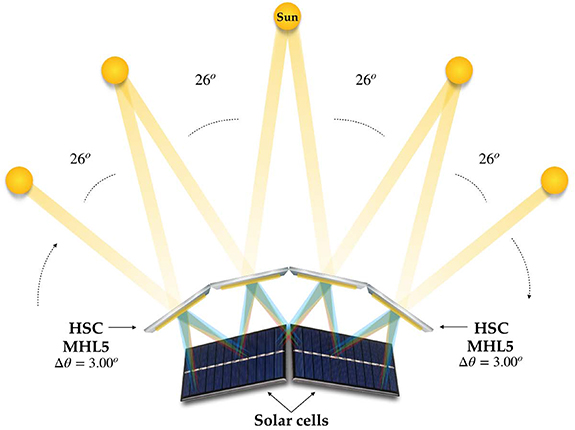
In this work, we present for the first time an HSC based on four MHL5 ( ) capable of achieving high diffraction efficiency (
 ) with a total acceptance angle
  (it would work from 38∘ to 142∘ incident angle) based on layers of approximately 170–180 µm physical thickness of low-toxicity and environmentally compatible photopolymer, Biophotopol (figure 6). One of the great advantages of working with this material is that it can be easily modified in the laboratory; therefore, its optimization is an active line of research. The future prospects of this work will be increase the Biophotopol layer thickness in order to increase the MHL with high diffraction efficiency. A greater number of multiplexed lenses in a thicker layer will optimize both the diffraction efficiency and the acceptance angle of the system.
Figure 6. Design of HSC composed by 4 MHL5 with  = 3.00∘.
Download figure:
Standard image High-resolution image
5. Conclusion
In conclusion, is difficult to reach at the same time high diffraction efficiency and wide acceptance angle in an HSC. Wide acceptance angles can be obtained by multiplexing holographic lenses in the same hologram. However, if the number of the MHL increases, the average diffraction efficiency decreases. The proposed HSC design based on four MHL5 with  reach a good agreement between acceptance angle (104∘) and an average diffraction efficiency (
 ) with negligible peak-to-valley variation. These results represent a great scientific achievement with respect to what has been previously published. Particularly, the fact that each multiplexed hologram (MHL5) with an angular distance between peaks (3.00∘) has a practically constant response in terms of short circuit current in an angular range of 26∘, which will allow in future works to expand this angular range while maintaining a high and nearly constant short-circuit current response. In addition, the HSC has been fabricated in Biophotopol, a low-toxicity and environmentally compatible photopolymer that can be optimised in each application. Moreover, the HSC and in particular the MHL is a versatile system that can be modified (number of multiplexed HLs, material thickness, angular distance between peaks) according to the needs of the intended application.
Acknowledgments
This research was funded by Universidad de Alicante (UAFPU20-23); Generalitat Valenciana (CIDEXG/2022/60, IDIFEDER/2021/014, PROMETEO/2021/006); Ministerio de Ciencia e Innovación (PID2019-106601RB-I00, PID2021-123124OB-I00).
Data availability statement
All data that support the findings of this study are included within the article (and any supplementary files).
Conflict of interest
The authors declare no conflicts of interest.
Supplementary data (0.8 MB MP4)