

Abstract
Light-emitting diodes (LEDs) are changing indoor wireless communications. Visible light communications (VLC) that use LEDs as transmitters is an emerging research area and has significant commercial potential. The light emitted from LEDs can simultaneously carry information and provide illumination. Due to the intrinsic characteristics of light, VLC is more secure, more power efficient, and can provide higher network data transmission rates than radio frequency communications. This paper describes state-of-the-art VLC systems including transmitters, receivers, and channel models. Modulation and networking algorithms for physical layer and cross-layer designs are discussed. These algorithms are designed considering practical constraints, such as the bandlimited channel, illumination requirements, and transmitted power limitations. Indoor localization algorithms are proposed, with a particular focus on fingerprinting. In addition, this paper introduces practical applications of VLC in many fields such as national defense, healthcare, robotics, and vehicle-to-vehicle communications. The paper concludes with a discussion of the challenges, opportunities, and future of VLC.
Export citation and abstract BibTeX RIS
Nomenclature
| ACO-OFDM | asymmetrically clipped optical OFDM |
| APD | avalanche photodiode |
| BER | bit error rate |
| CDMA | code division multiple access |
| CEO-OFDM | clipping-enhanced optical OFDM |
| DCO-OFDM | DC-biased optical OFDM |
| HCM | Hadamard coded modulation |
| IoT | internet of things |
| JOW | joint optimal waveform |
| LED | light-emitting diodes |
| LOS | line-of-sight |
| MAI | multiple access interference |
| MIMO | multiple input multiple output |
| NLOS | non-line-of-sight |
| OCDMA | optical code division multiple access |
| OFDM | orthogonal frequency division multiplexing |
| OOC | optical orthogonal code |
| OOK | on–off keying |
| OWC | optical wireless communications |
| PAJO | power allocation joint optimization |
| PAM | pulse amplitude modulation |
| PAPR | peak to average power ratio |
| PD-PAJO | partial decentralized PAJO |
| PPM | pulse position modulation |
| QAM | quadrature amplitude modulation |
| RF | radio frequency |
| RSS | received signal strength |
| SINR | signal to interference plus noise ratio |
| SNR | signal to noise ratio |
| TDMA | time division multiple access |
| U-OFDM | unipolar OFDM |
| VLC | visible light communications |
| VLP | visible light positioning |
| WD-PAJO | weighted decentralized PAJO |
1. Introduction
Optical wireless communications (OWC) refers to transmitting data using an unguided propagation medium, such as visible light, infrared, or ultraviolet. In the 1960s, Bell Labs first transmitted data via a laser beam, which led to the development of the field of OWC [1]. Over the decades, research and applications of OWC have focused on military and deep space communications, which has a limited prospect for civilian use [2]. The advent of diffuse infrared communications provided a promising solution for short-range communications [3, 4]. However, the market for infrared communications was still limited to such devices as TV remote controls. In recent years, with the emergence of visible light communications (VLC) enabled by white lighting LEDs, the market for OWC has begun to show potential and opportunities. Since VLC is used as a dual system (illumination and communications), it can be widely adopted in indoor and outdoor communications. VLC can be used to build smart lighting systems, create vehicle-to-vehicle networks and provide location-based services.
1.1. Recent development and potential of VLC
Visible light corresponds to wavelengths ranging from 380 to 750 nm in the electromagnetic spectrum, which are perceptible by the human eye. The idea of using fast switching light-emitting diodes (LEDs) to provide high-speed data transmission and illumination was first proposed in 1999 [5]. Since then VLC has seen rapid development and garnered much interest from researchers. In order to realize safe, efficient communications using visible light, the Visible Light Communication Consortium (VLCC) was established to promote and standardize VLC technology in 2007 [6]. The 'Smart Lighting Engineering Research Center' was founded in the Rensselaer Polytechnic Institute in the United States [7]. More than 20 European countries also launched a research project action named 'OPTICWISE', which aimed to provide a platform for interdisciplinary OWC research [8]. In 2011, the IEEE standard for VLC was first published as IEEE 802.15.7, establishing a guide for VLC industrial applications [9]. The 'Li-Fi Research and Development Centre' at the University of Edinburgh was formed in 2013 and conducts research in collaboration with industry [10]. VLC is an alternative wireless communication method that has many advantages compared to radio frequency (RF). Unlike RF whose spectrum is allocated to civil and military use, primarily to support data-heavy wireless communications, there is no spectrum regulation for VLC. LEDs are highly efficient and have a long life expectancy, rendering them ideal for widespread use for lighting and indication purposes [11–13]. In addition, since LEDs are easy to modulate, VLC systems can readily be integrated into pre-existing LED-based lighting infrastructure. Practical applications of VLC include outdoor and indoor smart lighting systems, location-based services, robotics, and industrial applications. VLC can also be used as a wireless connection method for the Internet of things (IoT) [14, 15]. Because of the growing potential of the VLC market, researchers from academia and industry have increasingly focused efforts on developing VLC systems [16–22].
1.2. Differences between VLC and RF communications
Due to their fundamental characteristics, there are many differences between VLC and RF systems. These differences include:
- the conventional modulation schemes adopted in RF communications cannot be directly applied in VLC because LED light is noncoherent. For RF systems, amplitude, frequency, and phase can be used to modulate signals. Since intensity modulation and direct detection (IM/DD) should be used for VLC systems, only real non-negative signals can be transmitted;
- indoor VLC systems are built based on existing or desired lighting systems; therefore, illumination is an essential function for VLC. For a typical office room, the illumination level should be around 400 lux [23]. A non-flickering and dimming controllable system is desired. For VLC, the transmitted optical power is equal to the illumination level; maximizing the signal power to interference plus noise ratio (SINR) should be considered as a design criterion, instead of minimizing the transmitted power, as in RF systems;
- for VLC systems, LEDs are usually used as transmitters. High power LEDs are required for lighting; however, lighting LEDs have a slow rise time that leads to a modulation bandwidth limit; the narrow bandwidth of LEDs limits the data transmission rate. Furthermore, a higher forward current driving the LEDs should stimulate more optical power; however, LEDs are nonlinear devices because they have a peak transmitted power constraint, which may distort the signals. When the value of the signal exceeds the constraint, the signal must be clipped. This effect is similar to the nonlinearity imposed by the power limit on RF high-power amplifiers, except that in VLC the limit asks on the signal, not the signal's power;
- VLC channels are highly predictable, unlike RF channels, which are often modeled as having a random phase and probabilistic fading (Rayleigh or Ricean). RF frequencies experience stronger wave diffraction and significant yet unpredictable transmission through objects. For VLC channels, on the other hand, we only need to estimate the light intensity and not the phase, as the LEDs generate noncoherent light. The signal intensities add directly, so there is not destructive interference to cause fading. The light can be modeled as a simple ray that does not transmit through opaque objects;
- the problem of indoor localization is an open research area that has attracted notable research interest in recent years. Since the signals from the global navigation satellite system are affected by multipath and attenuation, using this system for indoor localization is unwise. Research on indoor positioning has traditionally focused on radio-frequency, sound signals and camera-based systems [24]. Recently, studies have shown that VLC systems can provide surprisingly accurate solutions for indoor localization applications [25]. VLC-based positioning (VLP) systems can be used in places such as hospitals, airports, museums and industrial plants, where other technologies often fail.
1.3. Literature review
Many techniques and algorithms suitable for VLC have been developed and applied to improve the performance of VLC systems. In this section, we survey some of the most significant papers on VLC algorithm designs and applications.
In the physical layer, coding and modulation algorithms have been developed to support high-speed and reliable optical wireless connections. Intensity modulation, such as pulse position modulation (PPM), is used to encode and modulate M bits by transmitting a single pulse in one of the 2M possible time slots [26–28]. To further improve the performance of PPM, modulation schemes such as trace-orthogonal PPM-space time block coding, expurgated PPM, and multiple pulse PPM codes have been proposed [29–32]. However, since PPM requires highly accurate synchronization and a large bandwidth, amplitude modulations, such as M-ary pulse amplitude modulation (M-PAM), have been proposed for VLC to achieve a higher spectral efficiency [33–39]. Combining PPM and PAM, [40] proposes a variable pulse amplitude modulation scheme that has the advantages of both PPM and PAM. In IEEE 802.15.7, color-shift keying is given as a physical layer modulation standard for short-range links [41]. Merging color-shift keying with PPM, a flicker-free modulation scheme for VLC is proposed in [42, 43].
Multi-carrier modulation schemes, such as orthogonal frequency division multiplexing (OFDM), can be used in VLC systems for high-speed transmission [44, 45]. Since each subcarrier in OFDM can be individually modulated and controlled, OFDM is more robust to frequency selective channels than single-carrier modulation schemes [46]. Because VLC uses IM/DD, RF OFDM schemes cannot be adopted in VLC directly. Therefore, optical OFDM schemes that make the signal real-valued and positive and therefore suitable for VLC have been developed. DC-biased optical OFDM (DCO-OFDM), asymmetrically clipped optical OFDM (ACO-OFDM) and unipolar OFDM(U-OFDM) are popular optical OFDM schemes that can transmit real, positive-valued signals. To address the peak transmitted power constraint, a clipping-enhanced optical OFDM (CEO-OFDM), further described below, has been proposed to reduce the distortions caused by the LED nonlinearity [47].
Various cross-layer algorithms have been designed to support multiple users in VLC systems. Precoding with multiple input multiple output (MIMO) is a popular approach to reduce multiple access interference (MAI). By transmitting coded signals, the received signal can be separated due to the predictable effects of the channel losses and precodes. A DC bias is usually added to the transmitted signals to make them non-negative [48, 49]. Color-shift keying modulation over tri-band (red–green–blue) LEDs using code division multiple access (CDMA) is proposed to support multiple users in [50, 51]. Tri-band LEDs can improve the data rate and increase the channel capacity by individually modulating the three color channels, tripling the throughput compared to single color LEDs. Spatial division multiple access can separate users by using their location information [52, 53]. Users' different locations result in channel loss differences, which are exploited in spatial division multiple access. OFDM-access is a multiplexing technique based on OFDM that is also used in multiuser VLC systems [54, 55].
VLP systems ideally piggy-back on an installed VLC system. In the literature, VLP systems use a receiver based either on an imaging detector (i.e. a camera) or a single photodetector (PD). PD-based VLP is better suited as a part of a VLC system since PDs can support higher bandwidths for higher downlink speeds than camera-based VLP [56]. In this paper, we only consider PD-based VLP and VLC systems.
PDs can use various signal features for localization, positioning, and tracking, such as received signal strength (RSS), time-of-arrival, angle-of-arrival, or channel state information (CSI) [57]. PD-based VLP algorithms can be divided into proximity, triangulation–trilateration, and fingerprinting [58]. For proximity algorithms, each LED has its unique identifier, which are shared with the users. When a user detects the identifier from an LED, the user can associate its location with the location of this LED [59]. Triangulation–trilateration algorithms use VLC signal features for positioning: triangulation uses angle-of-arrival measurements, and trilateration uses distance information extracted from the RSS [57]. Fingerprinting algorithms use a previously collected database of location-related measurement information, e.g. the RSS [60].
1.4. Paper contribution and organization
In this review paper, we address a few important research areas in indoor VLC: physical layer algorithm design, cross-layer design, and VLC applications. Compared with recent published survey papers [61–64], this paper focuses on reviewing modulation schemes, network designs for multiuser VLC systems, and indoor positioning and tracking schemes using VLC. These schemes are compared with published algorithms as performance benchmarks. In addition, we share our vision of the potential for development and commercialization of VLC techniques.
The rest of the paper is organized as follows. Section 2 discusses the VLC transmitter, receiver, and channel models. In section 3, state-of-the-art VLC techniques for the physical layer are reviewed and discussed, including waveform design algorithms, a Hadamard code-based modulation scheme, and the clipping-enhanced optical OFDM technique introduced above. Cross-layer algorithm designs are discussed in section 4. VLC positioning and other practical applications of VLC systems are presented in sections 5 and 6, respectively. Finally, conclusions, as well as challenges and opportunities of indoor VLC, are discussed in section 7.
2. VLC system overview
An overview of the building blocks of a VLC system is given in this section. A typical VLC system consists of a transmitter, a channel and a receiver. A configuration of an indoor VLC system is shown in figure 1. Dual-use VLC systems employ the lighting fixtures as network access points. In this figure, several LED lamps provide illumination and high-speed data access to multiple users in the indoor area. Users located in the areas illuminated by multiple light sources can be served by these lamps. A handover scheme needs to be used for a mobile user transitioning from one access area to another.

Figure 1. Configuration of a typical indoor VLC system.
Download figure:
Standard image High-resolution image2.1. VLC transmitter
The slow rise-time of current lighting LEDs is a key factor that limits the VLC throughput; commonly used commercial devices have a 3 dB bandwidth of a few tens of MHz [65, 66]. Laser diodes have recently been proposed as light sources for VLC systems due to their large bandwidths [67–69]. However, laser diodes require considerable diffusing; otherwise, they can only provide a limited illumination coverage that is not suitable for regular lighting facilities. Micro-LEDs are another emerging light source technology that can support data rates of several Gbps [70–72]. Because of their weak radiation power, one would require thousands of micro-LED for practical illumination, which creates a hardware integration challenge.
In this paper, we assume white lighting LEDs are used as transmitters as shown in a functional block diagram in figure 2(a), where the LED is modeled as a combination of a nonlinear device and lowpass filter (LPF). The nonlinearity of the LED constrains the output optical power to be within an allowable range, as shown in figure 2(b). When the input signal exceeds this range, it must be hard clipped so the output does not exceed the peak power limit. Figure 2(c) illustrates the frequency response of an LED as a lowpass device that can be modeled as a first-order LPF [73]. When designing a VLC system, the bandwidth limitation and nonlinearity of LEDs are two important concerns [65, 74].

Figure 2. (a) A block diagram of an LED transmitter (b) LED input current and output optical power response, (c) LED frequency response.
Download figure:
Standard image High-resolution imageIn this paper, we employ a multi-LED configuration for indoor VLC as shown in figure 3. In this figure, the lamp consists of several small LEDs with different irradiation directions, and each of the LEDs on the lamp covers a small illumination area [75]. With the proposed geometry, the multi-LED lamp can provide a brighter and more uniform illumination than a single-LED lamp. In addition, each of the LEDs can be modulated and controlled independently, which provides flexibility for modulation, dimming design, and spatial multiplexing in multiuser environments.

Figure 3. Multi-LED lamp model, (a) side view, (b) bottom view [75].
Download figure:
Standard image High-resolution image2.2. VLC receiver
One of two types of receivers is used in current VLC systems: a PD or an imaging sensor [76–78]. Imaging sensors use a camera to capture the visible light signal, then determine the intended data. PD receivers contain a semiconductor device that is used to convert the optical received intensity to an electrical signal. When comparing imaging sensors with PDs, note that common PDs can support over 1 Gsps (Giga-symbols per second), more than 3000 times higher symbol rate than imaging sensors [56, 79]. Therefore, in this paper, we focus on PD-based VLC systems.
In the design of the PD receiver, bandwidth, responsivity, and noise level are three factors that need to be considered. A standard PIN (positive-intrinsic-negative) photodiode is typically used. However, other PDs such as avalanche photodiodes (APDs) are an attractive alternative due to their high responsivity [80–84]. Unfortunately, the bandwidth of an APD is limited, which is crucial for VLC systems. Furthermore, APDs require a more complex hardware design to provide the high electric field they need; device design and fabrication as well as hardware implementations are beyond the scope of this review paper. We focus on the functional design and configuration of receivers, based on which we can develop algorithms to improve the performance of VLC systems.
Figure 4 represents a multi-detector model for VLC systems similar to one proposed in [86] that is robust to shadowing effects [85]. The receiver has multiple detectors to achieve spatial diversity in the received signal. When the signal from one transmitter is blocked, the receiver does not lose connection since the intended data can be received from other LED lamps [52, 75]. A multi-detector receiver can also reduce the interference from sunlight. Sunlight with high intensity can introduce severe shot noise on the PDs that are pointed towards it as shown in figure 5(a). With the help of the multi-detector receiver and a MIMO technique, the signal from other directions can be received without suffering from the added noise due to the sunlight.

Figure 4. Multi-detector model structure, (a) 4-detector model, top and side view, (b) 7-detector model, top and side view [85].
Download figure:
Standard image High-resolution image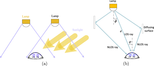
Figure 5. (a) MIMO VLC system exposed to ambient light. (b) Classification of light rays in modeling the channel response.
Download figure:
Standard image High-resolution image2.3. Channel model
For indoor VLC systems, the received signal can be represented as

where ρ represents the PD responsivity, i.e. the conversion ratio from the optical input power to the electrical output current. Ar is the area of the PD. The operator '*' denotes convolution, x(t) is the transmitted optical intensity, and n(t) is the additive noise that includes thermal and shot noises. h(t) is the indoor channel impulse response that can be modeled as

where hLOS(t) and hNLOS(t) are the line-of-sight (LOS) and non-line-of-sight (NLOS) parts of the received light, respectively. The LOS part represents the light that is received directly from the LED; the NLOS part is caused by multiple reflections from the walls as shown in figure 5(b). An example of a normalized impulse response of an indoor VLC channel is illustrated in figure 6, in which the first peak is the LOS part, and the other peaks with long tails are caused by the NLOS components. Given specific information about an indoor environment, the impulse response can be approximated by using ray tracing [87].

Download figure:
Standard image High-resolution imageFor commonly used lighting LEDs, the intensity of the emitted light for a particular radiation angle ϕ can be modeled using the Lambertian rule [87]. The LOS link gain between a transmitter and a receiver can thus be described as

where d is the propagation distance and φ represents the incident angle at the receiver, as shown in figure 5(b). The parameter m represents the Lambertian mode, which depends on the LED's beamwidth semiangle. Note that the use of a light diffuser would change the beam characteristics.
The channel gain of each NLOS ray can be calculated as

where ς is the wall reflection coefficient, and ℓi represents the ith bounce link attenuation,

where dk represents the distance of the kth bounce link. ϕk and φk are the radiation angle and incident angle at the kth bounce's diffusion point, respectively [89].
The complete impulse response is constructed by summing the LOS and NLOS components with their appropriate gains and their delays based on the propagation distance of the ray from lamp to receiver.
3. Physical layer algorithm design for VLC
For IM/DD systems, on–off keying (OOK) is a classical modulation scheme [33–35]. However, a high throughput is often required when transmitting a large amount of data, and OOK-modulated LEDs cannot support high-speed demands. In this section, several higher-order modulation algorithms for VLC are discussed considering practical concerns, such as the LED bandwidth limitation, transmitted power constraint, and illumination requirements.
For VLC systems, single-carrier and multicarrier modulations are two competing schemes that have respective advantages and disadvantages. For single-carrier modulation, M-PAM is one of the most power efficient modulation schemes for VLC. However, the bandlimited channel degrades the performance of M-PAM. Multi-carrier modulation, such as OFDM, can make better use of the limited LED bandwidth. Unfortunately, the high peak-to-average power ratio of OFDM can introduce distortion due to the peak power limitation of LEDs. Hadamard coded modulation (HCM) is an alternative scheme to OFDM that provides a low peak-to-average power ratio. M-PAM, various OFDM techniques, and HCM are discussed here.
3.1. M-PAM based waveform design for multiuser systems
Since currently available lighting LEDs are bandlimited to a few tens of MHz [90], the bandwidth of the overall VLC channel including the transmitter, indoor channel and receiver is dominated by the LED response. To improve the bandwidth efficiency and throughput, equalization algorithms including pre/post-equalizers have been proposed and applied in VLC systems [66, 91–94]. Higher order modulation, such as M-PAM can be used to enhance the throughput [38, 39, 95, 96]. We recently proposed a joint optimal waveform (JOW) design algorithm using adaptive M-PAM to overcome the bandlimited LED channel for multiple users [73, 97]. The MAI caused by the multiple users and the intersymbol interference (ISI) caused by the bandlimited channel can be reduced by using JOW.
JOW jointly optimizes the transmitted waveforms and minimum mean squared error (MMSE) receiver equalization filters. Block diagrams of the JOW transmitter and receiver are shown in figure 7. In this figure, there are Q LED lamps and K active users, and each LED lamp serves all the users. fqk represents the uniquely designed waveform modulated on the qth lamp for user k, where q = 1, 2, ⋯, Q and k = 1, 2, ⋯, K; the signal transmitted by the lamp is the sum of the signals intended for the K users. The number of samples that define the waveform, Lf, is a design parameter, and the more samples used, the better the performance, yet the higher the optimization complexity. The vector wk is the MMSE filter at user kth's receiver.

Figure 7. Block diagrams of (a) a JOW transmitter and (b) a JOW receiver [73].
Download figure:
Standard image High-resolution imageIn a multiuser system, the MAI, ISI, and additive noise all impact the system performance. Using JOW, the waveforms and MMSE filters are jointly optimized to maximize the signal to interference plus noise ratio (SINR). Since this optimization problem is nonlinear and non-convex, a genetic algorithm is applied to find the optimal waveforms [97]. If the genetic algorithm is too computationally intensive for a particular application, an offline JOW can be employed, as described in [73]. For the offline JOW, a look-up table of the waveform is calculated in advance, and the only real-time computational cost is memory storage space for the look-up table.
Parameters used for our numerical results showing the JOW performance are given in table 1. Both shot and thermal noises are considered for this case, assuming significant background light leading to a high noise spectral density. Figure 8(a) shows the bit error rate (BER) for a system using M-PAM modulation with various multiple access schemes: time division multiple access (TDMA), optical code division multiple access (OCDMA) using optical orthogonal codes (OOCs), and JOW. JOW can provide a lower BER than OCDMA and TDMA due to a better reduction of the ISI.

Figure 8. (a) BER comparison of JOW, OCDMA and TDMA for 3 users as the total bit rate increases (b) BER of JOW as the number of users increases.
Download figure:
Standard image High-resolution imageTable 1. Parameters used for JOW.
| Room size | 5 m × 5 m × 3 m |
| Number of lamps, Q | 4 |
| Lamp locations (m) | (1.25, 1.25, 3), (1.25, 3.75, 3) |
| (3.75, 1.25, 3), (3.75, 3.75, 3) | |
| User locations (m) | (1.0, 2.2, 0.8), (1.5, 1.5, 0.8) |
| (2.5, 3.4, 0.8), (4.3,2.5, 0.8) | |
| (4.0, 2.1, 0.8), (3.3,2.6, 0.8) | |
| (2.2, 1.8, 0.8) | |
| Responsivity, ρ | 0.5 A W−1 |
| Area of the PD, Ar | 0.01 cm2 |
| Peak radiated optical power per lamp | 3 W |
| LED semiangle | 60o |
| Noise spectral density, N0 | 10−9 mW Hz−1 |
| 3 dB bandwidth of LEDs | 20 MHz |
| Modulation constellation size, M | 8 |
The performance of the JOW design is affected by the number of users in the system. Figure 8(b) shows the average BER achieved using JOW for a different number of users. As the number of users increases, the BER performs worse due to the MAI. In this figure, when the number of users exceeds the number of samples used to describe the waveforms, the MAI dominates over the ISI. For a multiuser system using JOW, the proper number of samples to define the waveform must be used to provide an acceptable communication performance.
3.2. Optical OFDM variants
Optical OFDM is a candidate modulation scheme often used in RF systems that has attracted attention for VLC systems [44, 54, 55, 98]. Since LEDs can only transmit non-negative and real signals, conventional RF-OFDM schemes cannot be directly adopted. Real-valued OFDM signals are obtained by using Hermitian symmetry on the input to the inverse fast Fourier transform [46]. Then another mechanism must be used to obtain non-negative signals for IM/DD transmission, such as DC-biased OFDM (DCO-OFDM), asymmetrically clipped optical OFDM (ACO-OFDM), and unipolar OFDM (U-OFDM) [99–101].
DCO-OFDM is a traditional optical OFDM scheme that adds a DC bias to the real bipolar signals at the output of a standard OFDM modulator. However, the DCO-OFDM signal is susceptible to clipping at zero and the maximum power, Pmax, if the modulation index is high. The modulation index controls the modulated signal magnitude. ACO-OFDM only modulates odd frequency subcarriers to eliminate the negative part of the signal. This also avoids introducing zero-clipping distortion. Since the even frequency subcarriers are set to zero for ACO-OFDM, its power and bandwidth efficiency is lower than DCO-OFDM. U-OFDM transmits the positive and negative parts of the bipolar signal successively, which also avoids zero-clipping distortion. However, the peak transmitted power constraint can introduce severe nonlinear distortion and degrade the system performance [46].
We recently proposed a technique called clipping-enhanced optical OFDM (CEO-OFDM) to reduce the peak power distortion of OFDM [47]. CEO-OFDM is similar to U-OFDM but uses an extra time slot to transmit and recover the clipped information. The principle of CEO-OFDM is illustrated in figure 9. The positive and negative components of the real-valued signals generated by the OFDM modulator (using Hermitian) symmetry are successively transmitted in time slots 1 and 2 as shown. The high-valued signals that exceed the peak transmitted power Pmax must be hard clipped, and the clipped portion is sent using a third time slot. At the receiver, the CEO-OFDM signal can be reconstructed to obtain the bipolar signal for demodulation.

Figure 9. Illustration of a CEO-OFDM signal [47].
Download figure:
Standard image High-resolution imageThe parameter used for our numerical results comparing OFDM schemes are given in table 2. No background light is considered for this case, making the noise spectral density lower than in table 1. Performance comparisons of DCO-, ACO-, U- and CEO-OFDM are shown in figure 10 for quadrature amplitude modulated subcarriers. Figure 10(a) shows the BER performance when the bandwidth limit of the system is ignored. The BER performance of all modulation schemes improves as the modulation index increases at first. Larger modulation indexes can introduce more clipping distortion, and thus the BER begins to increase after reaching an optimal value. Comparing DCO-, ACO-, U- and CEO-OFDM, the minimum achievable BER of CEO-OFDM is much lower than that of the other three. This gives a potential for higher data rates for CEO-OFDM than for DCO-, ACO- and U-OFDM.

Figure 10. (a) BER comparison of DCO-, U-, ACO- and CEO-OFDM for different modulation indexes. The bit rate for 32-QAM is 1.25 Gbps, and for 64-QAM is 1.5 Gbps [47]. (b) Maximum throughput comparison for a 3 dB LED bandwidth of 20 MHz.
Download figure:
Standard image High-resolution imageTable 2. Parameters used for OFDM.
| Channel loss, h | 1 |
| Responsivity, ρ | 0.9 A W−1 |
| Peak optical power limit, Pmax | 8 mW |
| Number of subcarriers | 64 |
| Noise spectral density, N0 | 3 × 10⁻¹¹ mW Hz−1 |
When a high data rate is needed and the bandlimit of the LED must be considered, a bit loading algorithm and single-tap equalizer can be used to improve the throughput. Figure 10(b) shows a maximum throughput comparison of DCO-, ACO-, U- and CEO-OFDM as a function of the LED peak power, assuming optimal subcarrier modulation index for each technique. From the results, CEO-OFDM can provide the highest bit rate among the OFDM techniques considered.
3.3. Hadamard coded modulation
HCM is a pulsed alternative to OFDM [102]. It is also a higher-order modulation, i.e. a bit-to-symbol mapper used to increase the spectral efficiency. As shown in figure 11(a), the HCM encoder multiplies a vector of N − 1 data symbols ![${\bf{u}}={[0,{u}_{1},\cdots ,{u}_{N-1}]}^{{\rm{T}}}$](https://content.cld.iop.org/journals/2515-7647/1/1/012001/revision2/jpphotonaaf74aieqn1.gif) (where N is a power of two) as follows as
(where N is a power of two) as follows as

where HN is the Hadamard matrix of order N, and  is the complement of HN. The complement of HN is a binary matrix in which each element c of the matrix is replaced by
  . The components of u are assumed to be modulated using M-PAM. The vector x is pulse shaped appropriately to form the signal x(t) in (1).

Figure 11. Functional block diagrams of the HCM (a) encoder and (b) decoder.
Download figure:
Standard image High-resolution imageThe decoding of HCM signals can be done using the decoder shown in figure 11(b) as follows

where y are samples of the received noisy signal y(t) in (1) after filtering. The HCM encoder and decoder can be implemented using fast Walsh–Hadamard transform, which has a computational complexity of order Nlog(N).
Table 3 shows the relative bandwidth required to transmit each of the codewords generated by HCM. In multiple access systems where some of the users or devices cannot transmit or receive high-bandwidth signals, HCM codewords that require a lower bandwidth can be assigned to those users.
Table 3. Normalized bandwidth required for each HCM codeword, N = 16.
| HCM code | Normalized bandwidth |
|---|---|
| h1, h3, h5, h7, h9, h11, h13, h15 | 1 |

|
1/2 |
| h4, h12 | 1/4 |
| h8 | 1/8 |
An advantage of HCM over other modulation schemes is that devices that do not require high-bandwidth, such as IoT sensors, can use a simple and low cost receiver structure to detect HCM signals. For example, in order to decode a binary signal carried by h8 in table 3, a simple circuit can be used to integrate over the first half and second half of the symbol time, and a comparator can be used to make a decision, which makes it exactly the same as a Manchester decoder. This eliminates the need for an analog-to-digital converter to decode binary signals carried by HCM codes. Furthermore, HCM can benefit from bit-loading by using higher order modulation on the codes that are less susceptible to dispersive channels. In this case the order of the M-PAM can be different for different codewords.
The DC component of the HCM signals can be reduced by sending  instead of
  , which is called DC-reduced HCM (DCR-HCM). This makes the first row of the Hadamard matrix unusable for data transmission. This sacrifices 1/N of the bandwidth in exchange for the following advantages:
- Improves the energy efficiency, i.e. allows a larger modulation index.
- Reduces the effect of any DC wander on the decoded signals since all the HCM rows that carry information are orthogonal to the DC component.
- Results in fewer levels for x, which simplifies the hardware and reduces the effect of the LED nonlinearity on the transmitted signals. Table 4 compares the number of levels required for HCM with that of DCR-HCM for different values of N and M, the modulation constellation size.
- Reduces the peak-to-average power ratio by decreasing the probability of large amplitudes of x, and the signals become less likely to be clipped by the transmitter due the the peak power limit.
Table 4. Number of levels for HCM and DCR-HCM.
| HCM size (N) | Constellation size (M) | Number of levels | |
|---|---|---|---|
| HCM | DCR-HCM | ||
| 2 | 5 | 2 | |
| 4 | 4 | 13 | 4 |
| 8 | 29 | 8 | |
| 2 | 9 | 4 | |
| 8 | 4 | 25 | 8 |
| 8 | 57 | 16 | |
| 2 | 17 | 8 | |
| 16 | 4 | 49 | 16 |
| 8 | 113 | 32 | |
The reduced DC level in DCR-HCM is per HCM symbol, and its value can be different from symbol to symbol. The same decoder structure as in figures 11(b) can be used to decode the received signals. Figure 12 shows an example of the reduction in unnecessary power in an HCM symbol of size N = 8, where the transmitted energy of the HCM symbol in figure 12(a) is reduced by a factor of 3/7 compared with its corresponding DCR-HCM symbol in figure 12(b).

Figure 12. (a) An HCM signal, and (b) its corresponding DC reduced signal [102].
Download figure:
Standard image High-resolution image4. Cross-layer algorithm design for VLC
Algorithms that combine the functions of media access control (MAC) and physical layers, so-called cross-layer approaches, need to be explored for indoor VLC system to support many users. Because the IM/DD channel is highly predictable, VLC is better suited than RF systems for using spatial multiplexing by exploiting information on the users' location. In this section, we discuss cross-layer algorithms based on spatial multiplexing. Practical considerations, such as limited transmitted power and computational burden, are taken into account.
4.1. Centralized power allocation joint optimization algorithm (PAJO)
Spatial information and CDMA can be used together with a power allocation algorithm to separate user signals that are spatially distributed, so that all users have access to a reliable wireless connection [52, 75]. With the help of MIMO signal processing, the transmitted power for each lamp and the MMSE filter for each user can be adaptively optimized to minimize the MAI and maximize the SINR. This approach, called the centralized PAJO, is described in this section.
Using MIMO, one user can be served by more than one LED, as described above in section 3.1. For a centralized PAJO, we assume that all LEDs in the room serve all users. A block diagram of the centralized PAJO is shown in figure 13. The allocated power and MMSE filter for each user can be jointly optimized to maximize the SINR. 'Fairness' and 'Min-BER' represent two commonly-used optimization criteria: to minimize the maximum BER among all the users, or to minimize the average BER over all the users. Since the optimization process is nonlinear and non-convex, a sequential quadratic programming method is employed. We discuss and compare the performances of these two optimization criteria.

Figure 13. A block diagram of the centralized PAJO.
Download figure:
Standard image High-resolution imageFor the techniques described in this section, OCDMA based on OOC is used as a multiplexing scheme to separate the user signals. Simple OOK modulation is applied here, as the purpose of the algorithm is to increase the network throughput via spatial multiplexing; M-PAM could be applied instead to further increase the individual user's bit rate.
We consider both small and large room scenarios. Unless otherwise noted, the parameters used for numerical and simulation results for the small room environment in this section are shown in table 1. Two scenarios are tested to obtain the BER performance of the centralized PAJO, as shown in figure 14(a). In Case 1, all the users are placed near one of the lamps in a small room with 4 LED lamps. In Case 2, all the users are distributed throughout the room. Numerical results for the BER of the centralized PAJO are presented in figure 14(b). From the results, Case 2 always has a better BER performance than Case 1 as the users locations allow for better spatial multiplexing. If an equal BER performance is needed among the users, the 'Fairness' method should be selected.

Figure 14. (a) Top-down view of the two typical user position cases in a small room. The circles represent the lamps and the squares represent the users. (b) BER performance for Cases 1 and 2 shown in (a) [52].
Download figure:
Standard image High-resolution imageA large 12.5 m × 12.5 m test indoor environment with 25 lamps and 50 users is shown in figure 15(a). All other parameters are as in table 1. In figure 15(b), we compare the performance of centralized PAJO with TDMA as the number of users increases. The OOC codes with length 13, 19 and 25 can support up to 26, 57 and 100 users, respectively [103]. From the results, when the number of users is large, PAJO can provide a higher bit rate since TDMA is less efficient than PAJO in that case. The results show that depending on the number of users, choosing the right OCDMA codes can always result in a higher bit rate by using PAJO than by using TDMA. In the figure, the highest throughput obtainable for this scenario is labeled 'PAJO, OOC optimal selection'.

Figure 15. (a) Top-down view of a large indoor environment. The circles represent the lamps and the squares represent the users. (b) Average bit rate as the numbers of users increases with PAJO and TDMA techniques; the desired BER is 10−3 [38].
Download figure:
Standard image High-resolution image4.2. Decentralized PAJOs
Finding the solution to PAJO is a nonlinear and non-convex optimization process, which is time-consuming and imposes a large computational burden when there are a large number of LEDs and users. Decentralized PAJO methods are desired to reduce the computational burden. Two of the decentralized algorithms proposed in [52] are summarized in this paper.
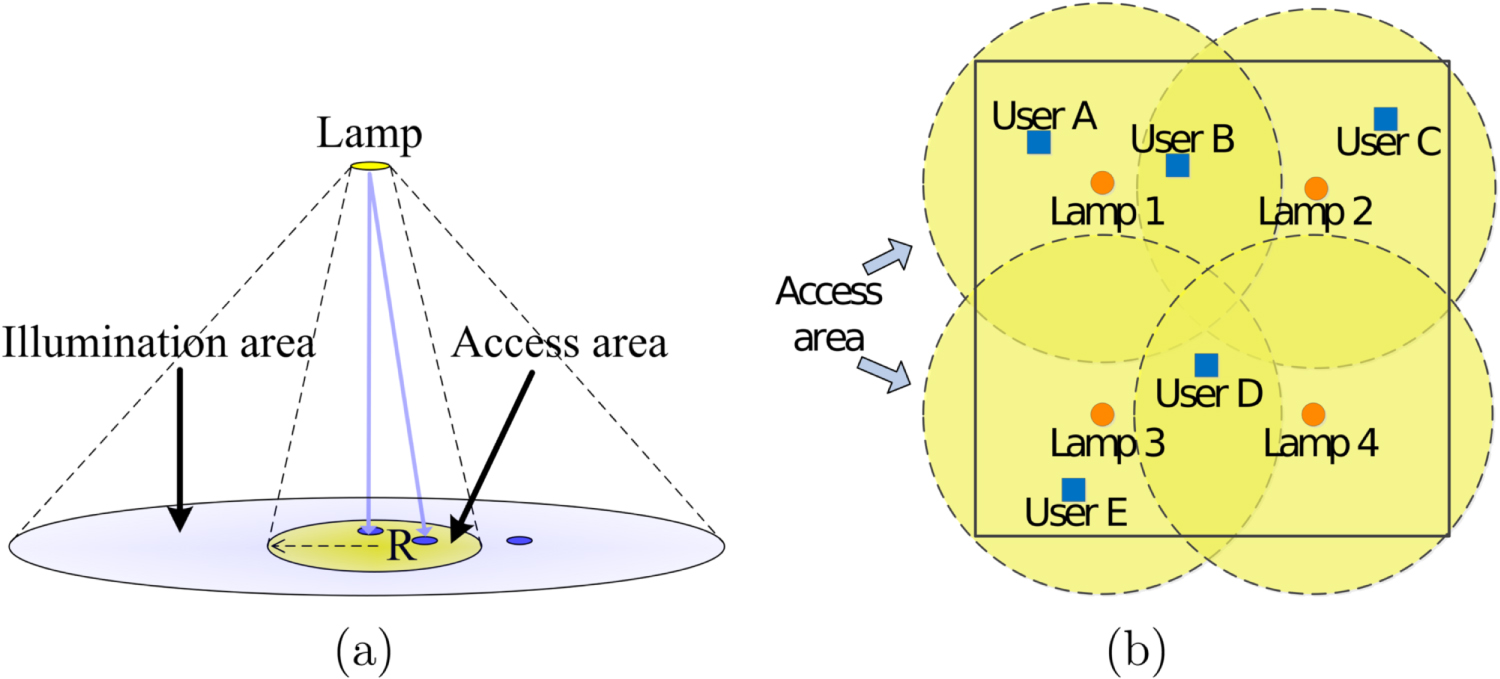
For the decentralized PAJO algorithms, we artificially define an access area for each lamp as shown in figure 16(a). This circular area is smaller than the actual illumination area so that the lamp can only serve the users who are in its access area. The radius of the access areas must be sufficiently large to cover all the indoor space. Users in regions where the access areas from different lamps overlap are served by these lamps together. An example of an indoor VLC space with four lamps serving five users is shown in figure 16(b). In this case, user B is located in the overlapping access areas of lamps 1 and 2, and it is therefore served by these lamps. Similarly, user D is served by lamps 3 and 4. Users A, C, and E are only served by lamps 1, 2 and 3, respectively.

Figure 16. (a) Illumination and access areas (the access area radius is R). (b) Geometric layout example for four lamps and five users. [52].
Download figure:
Standard image High-resolution imageDepending on the users' locations, lamps and users in the indoor environment can be divided into optimization threads. Two decentralized algorithms that define these threads differently are described here. In the partial decentralized PAJO (PD-PAJO), lamps that serve the same users solve the resource allocation problem together in the same optimization thread; they jointly allocate the transmitted power. Otherwise, lamps form independent optimization threads. Since all the optimization threads can operate separately and in parallel, the computational time can be reduced compared with the centralized PAJO [104]. The users and lamps in the example shown in figure 16(b) can be divided into two optimization threads. Since user B is served by both lamps 1 and 2, the first optimization thread includes lamps 1 and 2, and users A, B and C. Similarly, lamps 3 and 4 and users D, E and F comprise the second optimization thread.
The weighted decentralized PAJO (WD-PAJO) is a completely decentralized algorithm. Each lamp works as an individual optimization thread. Unlike PD-PAJO, there is no collaboration between lamps, although multiple lamps can serve one user. When optimizing the power allocation using WD-PAJO, the calculated SINR for each user is multiplied by a weight to account for the number of lamps serving this user. This multiplicative weight is used to compensate the SINR since each lamp works individually [104]. For the example shown in figure 16(b), four optimization threads are created when WD-PAJO is used. The weight for the SINR of user B is 2, since two lamps serve this user. Similarly, the weight for user D is 2. For all other users, the weight is 1.
4.3. Computation and BER analyses
Figure 17 illustrates the optimization threads created in PD-PAJO, WD-PAJO, and the centralized PAJO. For the centralized PAJO, each lamp serves all the users, and so in a large room with a large number of users, the optimization is extremely time-consuming. PD-PAJO and WD-PAJO can efficiently reduce the computational time and burden by defining small access areas and dividing the lamps and users into parallel optimization threads. In figure 17, since each lamp in PD-PAJO and WD-PAJO only needs to serve the users who are located in its own access area, the number of variables that needs to be optimized per optimization thread is much lower than the centralized PAJO. WD-PAJO has lower computational burden than PD-OFDM since each lamp works individually and there is no collaboration between lamps.

Figure 17. Difference between the access point information exchange for (a) the centralized PAJO , (b) PD-PAJO , and (c) WD-PAJO cases [104].
Download figure:
Standard image High-resolution imageA comparison of the computation time required to solve the optimization problem between the centralized PAJO and decentralized PAJO algorithms is shown in table 5. In this example, a 12.5 m × 12.5 m × 3 m large room with 25 uniformly distributed LED lamps and 50 users is used, as above. From the results, the running time of PD-PAJO and WD-PAJO is only 0.7% and 0.04% that of the centralized PAJO, respectively4 .
Table 5. Time consumption comparison of algorithms, large room case [52].
| Running time/Thread, s | |
|---|---|
| Centralized PAJO | 2.62 × 10⁴ |
| PD-PAJO | 1.93 × 10² |
| WD-PAJO | 8.65 |
The BER performance of PD-PAJO and WD-PAJO is shown in figure 18. In this figure, different access area radii are compared. For PD-PAJO, more users are located in overlapping access areas as the size of the access area increases, and then more lamps need to work together to allocate the power resources. PD-PAJO converges to the centralized PAJO for a sufficiently large access area. Based on the environment geometry tested, R = 1.77 m is the minimum radius access area needed to cover all the indoor space. From the results shown in figure 18, there is about a 2 dB power penalty for PD-PAJO using the minimum access area compared to the centralized PAJO when the BERs are the same. The WD-PAJO's BER performs worse for a larger access area, as expected and confirmed in figure 18. For WD-PAJO, an increasing access area leads to a BER that diverges from that of the centralized PAJO. In the case of an extremely large access area radius (on the scale of the room dimension), the weight to compensate the SINR for each user is the same; the WD-PAJO then fails to work. For the minimum access area, WD-PAJO has a similar BER performance as PD-PAJO.

Figure 18. BER performance of the centralized PAJO, PD-PAJO and WD-PAJO.
Download figure:
Standard image High-resolution image5. VLC indoor positioning
LEDs installed for communications can also be leveraged for indoor positioning and tracking. Using VLC systems, highly accurate positioning and tracking performance can be achieved for indoor users. Triangulation–trilateration, proximity, and fingerprinting are the three most widely used algorithms for indoor VLP systems. Triangulation–trilateration algorithms rely on the VLC channel quality; even slight variations in the SINR can degrade the performance significantly. A dense grid of LEDs is required to utilize proximity algorithms, which is not deemed practical. On the other hand, fingerprint-based VLP algorithms use a pre-existing database of CSI; they are popular due to their robustness to SNR variations and resilience against obstructions in the channel. We focus on this latter technique.
5.1. Fingerprint-based VLP
A fingerprint is defined as a measurable quantity at a known location, e.g., the RSS. Figure 19 shows how a fingerprint-based indoor positioning algorithm works. It consists of two steps: an offline part and online measurements. In the offline step, the fingerprints (CSI) are collected and stored in a database. This process is generally known as a 'site survey'. The site survey is the most challenging part of fingerprint algorithms since it requires much time, labor, and frequent updates over time as channel conditions change. The online step starts with real-time measurements, which are used in a pattern matching algorithm, such as nearest neighbor, probabilistic filter, or correlation, to locate the user [57].

Figure 19. Steps followed in a fingerprint-based VLP algorithm [60].
Download figure:
Standard image High-resolution image5.1.1. Probabilistic tracking filters used in fingerprint-based VLP
A fingerprint database can be used to track the user with a probabilistic tracking filter such as an extended Kalman filter (EKF) or a particle filter (PF).
The EKF consists of two steps: a prediction step and an update step. In the prediction step, the system is simulated through the state dynamic equation, and a predicted state is obtained. The system is modeled as

where A is the state matrix that describes the expected motion of the user, xk is the state vector consisting of the user's location and velocity, and yk is the measurement vector of optical RSS from each lamp, both at time sample k. The process noise of the state is qk, and nk is the measurement noise, assumed to be zero mean, Gaussian, and independent. z(·) is the measurement model function that relates the RSS to the state variables.
In its formulation, the EKF can use the Jacobian of the measurement model z(·) to linearize the relation between the measurements and the state variables. The VLC LOS channel model given in (3) is a closed-form nonlinear function of a user's location. However, using (3) is impractical when the incidence and irradiance angles between the LED and the PD are unavailable. Instead of calculating the Jacobian, the fingerprint database can be used in a finite difference equation to approximate the Jacobian  of
of  , as proposed in [60]. The RSS of the predicted state of the user is shown as
  in figure 20(a). Using the fingerprint database, the RSS data at the cardinal points, P(i±1, j±1), of
  are used in

to estimate the Jacobian  that is used to calculate the Kalman gain in the EKF. In (9), Δx and Δy define the resolution of the grid used to compute the fingerprint map.

Figure 20. Bird's-eye view of a room with a single LED lamp illustrating the fingerprint database used in probabilistic tracking filters: (a) a finite difference method based linearization for the EKF, (b) simulation of particles for the PF [88].
Download figure:
Standard image High-resolution imagePF is a Monte Carlo algorithm that can estimate the internal state of a dynamic system by using Bayesian statistical inference [105]. For indoor VLP tracking algorithms, the PF can also use the fingerprint database to estimate a user's location, as shown in figure 20(b). A PF uses multiple representations of the state, also known as particles, to simulate the system [105]. The fingerprint database is used as a look-up table for the particles that are simulated through the state matrix A of the dynamic model given in (8). Each particle has a weight based on its likelihood, and picking the particle with the highest weight (maximum likelihood) can best estimate the state of the user. A more detailed explanation of how the PF is used with an RSS-fingerprint database can be found in [88].
5.1.2. Effect of lamp types and fingerprint resolution on tracking
In this section, the indoor area is divided into a rectangular grid, and the size of the grid elements Δx = Δy represents the site-survey resolution. The LED lamp described in figure 3 is compared with an LED lamp with random irradiance angles, used to model a random lamp, e.g. a chandelier, which results in a random RSS distribution in the room. Figure 21 shows the illumination distribution for a multi-LED lamp that has no randomness and one that has a random irradiance angles.

Figure 21. Bird's eye view of the illumination contours on the room floor: (a) multi-LED lamp in figure 3, and (b) multi-LED lamp with random irradiance angles [60].
Download figure:
Standard image High-resolution imageFigure 22 shows performance comparisons of the EKF and trilateration methods using different types of lamps and grid step sizes. The grid step sizes for low and high resolutions are chosen as 10 cm and 1 cm, respectively. For these results, fingerprint maps are obtained using a single-LED lamp, the multi-LED lamp in figure 3, or a random irradiance-angle multi-LED lamp. An S-shaped trajectory in a small room is used to simulate the trajectory of the user. The parameters used for the simulation are given in table 1. From the results, fingerprint-based VLP with the EKF can provide a smaller root mean square error (RMSE) of the user location than trilateration-based VLP when the SNR is low since the performance of trilateration relies heavily on the VLC link quality. The EKF uses the pre-existing fingerprint database, and, therefore, a low SNR does not affect the tracking accuracy as significantly.

Figure 22. Root mean square error (RMSE) of the user location estimate for the EKF and trilateration methods with different lamp types and fingerprint resolutions [60].
Download figure:
Standard image High-resolution imageThe tracking error for fingerprints obtained from random lamps is similar to that of nonrandom lamps for moderate SNR values. However, the lamp randomness combined with low SNR values for a high resolution map has a destructive effect on tracking accuracy. Note that trilateration cannot be employed for random lamps. For high SNR values, the tracking error of fingerprint-based algorithm is dominated by the resolution of the fingerprint map that generates a quantization error [88]. Therefore, fingerprint maps with a higher resolution can provide a smaller tracking error. Although these plots are for the EKF, tracking using a PF results in a similar RMSE performance, as shown in [88].
5.1.3. Effect of shadowing on fingerprint-based VLP
In general, fingerprint databases are collected for identical lamps under the same conditions. However, different lamps may be affected by unknown shadowing in the system, i.e. unforeseen obstructions in the LOS that may lead to varying SNR levels for each lamp in real-time operation. Shadowing is considered catastrophic for most VLC and VLP systems. In this section, how shadowing can affect fingerprint-based VLP tracking systems is discussed.
Figure 23(a) shows the effect of shadowing on the performance of the EKF and PF systems described above. As a comparison benchmark, the performance of the trilateration algorithm is included using the same parameters as the EKF and PF algorithms. In this figure, we assume that the shadowing degrades the received SNR, measured as a dB loss. Only one of the four lamps in the room has an unknown shadowing loss and the rest of the lamps operate normally at 45 dB SNR. From the result, the trilateration algorithm is significantly affected by the shadowing, as expected. However, the EKF and PF using the fingerprint map are robust to shadowing since the fingerprint database is collected in advance. Figure 23(b) shows a typical scenario where the EKF is used for tracking an S-shaped user's trajectory. In this experiment, the unknown shadowing for the labelled LED lamp creates a bias in the estimated trajectory, especially if the user is close to that lamp. The effect of the shadowed lamp on the tracking error reduces as the user moves away.

Figure 23. Effect of shadowing on tracking performance: (a) RMSE of position estimate for different shadowing loss levels, SNR = 45 dB, and (b) sample tracking result when one lamp has unknown shadowing with a loss of 3 dB [88].
Download figure:
Standard image High-resolution image5.2. Simultaneous lamp and user localization
State-of-the-art VLP algorithms assume that they are given the exact position of the LED lamps. In reality, an LED discovery step is necessary for cases when there are LED installation unknowns, or the LED infrastructure was not installed with indoor positioning applications in mind. A distance geometry technique, given in [106], can be used for positioning the LEDs using the user's RSS measurements. However, the algorithm in [106] cannot be used when the displacement of the user is small, and collinearity makes the solution of the geometric equations inaccurate. In this section, we introduce a method that uses crowdsourcing to collect RSS measurements from multiple users to alleviate these problems [107].
Figure 24(a) shows the effect of the SNR on the user tracking error using an EKF when the LED locations are estimated. The unknown LED locations are discovered by using extensions of the method given in [106]. The results show that using crowdsourced measurements (six users, dashed lines) significantly improves on the performance of the single user algorithm proposed in [106] (solid lines).

Figure 24. LED and user equipment (UE) localization using tetrahedron-based distance geometry. (a) User localization using a single user versus six users sourced measurements. (b) Typical scenario for the proposed method at an SNR of 65 dB showing the user's true trajectory (solid line) and the estimated trajectory (dashed line). The yellow triangles are the true LED locations, and the red dots are estimated LED locations [107].
Download figure:
Standard image High-resolution imageFigure 24(b) shows a typical realization of localizing the LEDs and tracking the user when the SNR is 65 dB. The measurements used in the EKF are the distance and the angle between the estimated location of the LED and the user. Figures 24(b) (i) shows the LED localization and user tracking for measurements sourced from a single user, while (ii) shows a scenario where measurements are sourced from six users. Using crowdsourced measurements results in a notable improvement in the user positioning accuracy.
6. Practical applications of VLC systems
More than 73% of data traffic will be loaded on Wi-Fi by 2021, which means more than a 640% increase in wireless traffic compared to 2016 [108] . This, in turn, is creating a 'perfect storm' for IoT. More than 30 billion devices are expected to be connected by 2020, and as more and more devices are connected to the Internet, a spectrum crunch is increasingly inevitable.
VLC uses LED lights to transmit data, and the growing interest in replacing traditional lighting sources with LED lights is creating a unique opportunity for VLC technology. Over 450 million LEDs have been installed to date in the US, up from less than half a million in 2009, and nearly 70% of Americans have purchased at least one LED bulb [109]. All told, energy-efficient lighting now accounts for 80% of all US lighting sales.
While there is a significant increase in wireless traffic demand, there is also a growing concern about using Wi-Fi due to security, electromagnetic interference, and health issues. IoT opens the door to a myriad of opportunities, and yet it also opens the door to many challenges, such as security. VLC can address some of these challenges: it will provide advantages such as zero electromagnetic interference, allowing connectivity even in areas where Wi-Fi is not accepted—hospitals and nuclear plants, for example. We describe these advantages and propose environments most suitable to VLC deployment.
6.1. Advantages of VLC-based applications
In this section, selected advantages of adopting VLC solutions in practical applications are described.
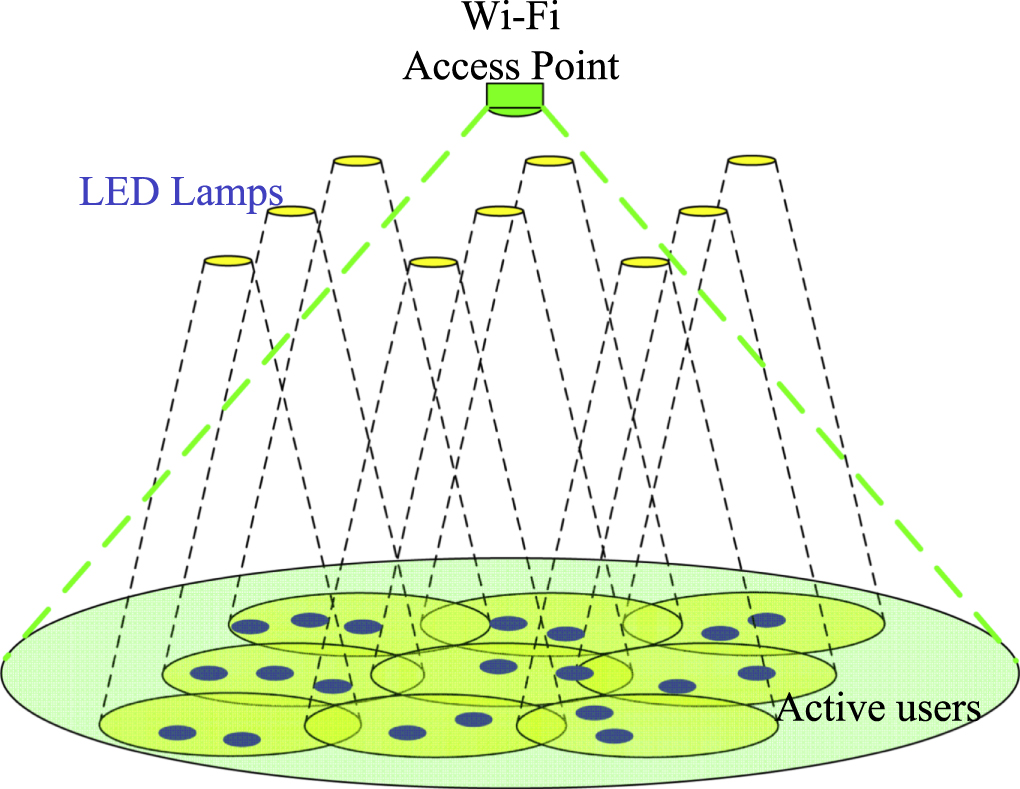
High density of users: Due to their limited spectrum and long reach, Wi-Fi systems cannot support a high density of users, which results in unreliable connections in crowded spaces such as airports, train stations, convention center, etc. VLC systems do not have their spectrum regulated and can provide reliable wireless access over their limited reach. Since each LED lamp illuminates a small area, it naturally builds a small access cell consisting of at most a few users; these users do not need to share the access point with users in other parts of the room. For an indoor environment with multiple LED lamps, as shown in figure 25, constructing a high density of access points can significantly increase the network capacity compared with Wi-Fi in which all users have to share the access point spectrum.

Figure 25. Example of a high density of users served by a multi-cell VLC system compared with a Wi-Fi access point.
Download figure:
Standard image High-resolution imageHigh connection security: VLC offers better physical-layer security and privacy than RF systems since light waves cannot pass through walls, making it nearly impossible to hack into sensitive facilities by collecting the wireless signal. In [110], we analyze and discuss the interception vulnerability of indoor VLC systems, specifically for a scenario consisting of a small room (5 m × 5 m × 3 m) with a window, as shown in figure 26. An area outside the window is defined as a vulnerability zone if the leakage of the signal strength is high enough so that it can be easily eavesdropped unless precautions are taken. The modulation index of the signal carried by the light can be adaptively adjusted to minimize the outdoor security risks and simultaneously maintain a reliable indoor communication quality.

Figure 26. Vulnerable area outside a room with a window [110].
Download figure:
Standard image High-resolution imageHigh positioning accuracy: Another advantage of VLC is that it provides a signal of opportunity for indoor centimeter-accuracy positioning, impossible with competing technologies. Using VLP, a highly-accurate indoor localization and real-time navigation services can be provided [25, 57]. VLP systems have garnered attention especially in the context of real-time location-based services and robotics applications. User-centered, location-related, and assist-focused applications are given in table 6 [111]. Based on a user's location and interest, real-time location-based services can make recommendations, provide advertising, and answer a user query. Furthermore, LEDs can be used as landmarks that serve as anchor points for robots during location-related tasks such as simultaneous mapping and localization indoors [112, 113]. The light emitted from LEDs can also be used to detect obstacles, such as walls and furniture; by using location information from reflections, an indoor map can be generated, as shown in figure 27 [113]. In addition, VLP can be combined with communications using VLC in assist-focused services, such as healthcare (patient tracking and monitoring), alerts, and remote sensing, by using the location information of the users and the data collected from the indoor environment; the information gathered can be transmitted using VLC.

Figure 27. Typical indoor mapping scenario. The yellow circles represent the LEDs on the ceiling, and the blue line is the user's trajectory. The estimated wall locations are represented with green and red squares.
Download figure:
Standard image High-resolution image
Table 6. Applications of real-time location-based services.
| User-centered | Location-related | Assist-focused |
|---|---|---|
| Advertisements | Navigation | Healthcare |
| Recommendation | Mapping | Alerts |
| Business | Guide services | Remote sensing and detection |
The rise in robotics research and development brings different challenges and opportunities at the same time. Imagine many robots each operating in a cluttered indoor area, such as a warehouse; communications play a critical role for these robots to understand the environment, locate themselves, and carry out their tasks. In such environments, RF-based communications create interference [114]. VLP systems can solve not only the RF interference issue but also increase the mobile robot positioning accuracy.
These advantages compound with the solid-state lighting revolution, including the movement towards power over Ethernet. The advent of LED lighting offers high power-efficiency, as well as faster and cheaper installations. Ethernet connectivity in every light fixture offers benefits in terms of building control and device monitoring. All of these developments pave the way for VLC to be an essential component of the IoT.
6.2. Potential VLC application environments
Given the market share and ubiquitous nature of RF technology, the adoption and implementation of VLC will require an intensive, well thought-out strategy that identifies critical needs and gaps that RF cannot fill. VLC solutions must outperform and come in at lower cost than competing RF technologies; otherwise, it will be relegated to niche markets. The following includes applications where VLC technology might thrive:
- government, defense, and financial institutions: This market is a particularly ideal target for VLC in that many agencies and/or services have strict guidelines and limitations on networking and communications, often resulting in restrictions in the use of RF and related technology. Adversaries can easily identify users of radio signals enabling them to not only hijack the information but also geo-locate to determine the position of a target. VLC is an ideal solution that can serve to provide a secure information link on an as-needed basis;
- warehouses and factories: Installing VLC-enabled lights in warehouses and factories can provide wireless connectivity throughout the facility for robots, automated guided vehicles, machines, and sensors, without concern for the network congestion. It can also enable precise real-time positioning and tracking for machinery and products including data analytics. Many of these facilities are currently spending tens of thousands of dollars on the installation and maintenance of their Wi-Fi networks, and still suffering from network congestion;
- healthcare: Hospitals offer a significant market opportunity for VLC technology. Currently, Wi-Fi cannot be used in some parts of a hospital due to health concerns for patients, interference effect on sensitive medical devices, or the security of medical records. VLC resolves the safety concerns, minimizes the electromagnetic interference on the operation and accuracy of sensitive equipment, and relieve security concerns. VLC may also be used for untethered patient monitoring;
- connected Vehicles: Many new vehicles already employ LED head and taillights that can be used to transmit data. VLC can be used to reduce interference for vehicle-to-vehicle links, and also solve RF congestion problems, offering secure links between vehicles. It can provide low latency when these links are only available for a short period of time, and can reduce the cost of all vehicle-to-X communications. Lastly, VLC can create an intra-vehicle network to connect the increasing number of electronic devices found in cars;
- IoT Devices: The increasing number of IoT devices makes network congestion a concern in most enterprise and industrial applications. Sensors and other electronics are often equipped with indicator LEDs that can be used as VLC transmitters. These devices usually require small bandwidth to share the data collected from sensors or send updates about the status of the system. VLC can be an ideal replacement for Wi-Fi or Bluetooth to transfer low-speed data. If the required data rates are low, a VLC NLOS link between the user and the access point suffices, enabling full environmental coverage;
- airlines: communications inside jet cabins constitutes a potential market for VLC technology since it can offer a high-speed internet connection over the duration of the flight without generating electromagnetic interference to radio-sensitive equipment on the flight deck. The reduction in equipment and cabling requirement also means a lighter aircraft;
- businesses: VLC offers a better solution than Wi-Fi in open office environments due to its multiuser capability, enabled by spatial multiplexing (resource reuse), security, and high-speed. Government buildings and facilities including embassies will also benefit from the high security of VLC. VLC could become the cornerstone of intelligent buildings;
- hotels/convention centers: high-speed internet access has become mainstream in hotels despite security concerns. VLC offers a secure and fast connection for all rooms and a more economical solution in large venues such as conference halls and ballrooms. These latter environments can result in an astonishingly high density of users during, e.g. lectures and exhibits;
- shopping malls and stores: VLC will provide internet access and localization services that will help users find what they are shopping for. It can facilitate information collections so that retailers can perform data analytics on, e.g. inventory.
7. Summary, challenges and opportunities
This paper reviews and discusses topics particular to indoor VLC systems and their applications. Based on our analysis, VLC has the potential to provide high-speed and high-security wireless connections and indoor location-based services. Compared with RF communications, VLC is more power efficient, can achieve higher throughput and has no spectrum regulation. Due to its advantages over RF communications, VLC has attracted considerable attention from researchers in academia and industry. This section summarizes our finding and addresses future developments.
7.1. Summary
In this paper, we provide an overview of indoor VLC systems that includes transmitter, receiver, and channel models. Based on our analysis, multi-LED transmitter and multi-detector receiver models are well suited to indoor VLC systems. With the help of MIMO techniques enabled by these devices, the resulting systems are robust to shadowing effects and sunlight interference, and are well-suited to benefit from novel signal processing algorithms.
Selected physical layer and cross-layer algorithms are also discussed in this paper. Specially designed modulation schemes in the physical layer can provide efficient data transmission, and can be adaptively designed to reduce the effects of practical constraints, such as a bandlimited channel and transmitter power limit. Cross-layer algorithms can support multiple users and improve the performance of indoor networks. A multi-cell network model using a cross-layer power allocation algorithm is described.
This paper also describes robust VLP algorithms. From our analysis and results, fingerprint-based localization algorithms have the potential for centimeter-accuracy when providing indoor location-based services.
7.2. Challenges and opportunities
Although VLC has many advantages and large market potentials, some challenges still exist and require further exploration.
One area requiring further investigation is the development of photonic devices specifically for dual-use lighting and VLC. Lighting devices with a high radiation power, fast rise-time and large illumination coverage range need to be developed. Current lighting LEDs have limited bandwidth; recently proposed micro-LEDs are difficulty to use for lighting due to their weak radiation power, and modern laser diodes have significant beamwidth and light-quality issues for regular illumination purposes. Challenges in the receiver design include broadening the field of view and increasing the signal power while maintaining a high bandwidth, limiting noise, and reducing the physical size. PIN photodiodes and APDs are two commonly used detectors in optical communication systems, each with its own strengths and weaknesses regarding bandwidth and responsivity. Specially designed transmitters and receivers for VLC systems are in urgent need of development.
Since visible light cannot penetrate objects, VLC channels can be easily blocked. Even if MIMO techniques and multi-detector receivers can be applied to reduce the shadowing effects, the channel quality remains sensitive to blocked and reflected light. Therefore, the shadowing and the user's surrounding environment interfere with the received signal power. A flexible yet accurate general physical channel model is needed for system design.
For a multiuser VLC system, moving users may introduce varying levels of MAI upon each other. Algorithms in the physical and the MAC layers can be designed to reduce the effects of MAI. In addition, since each light source can only illuminate a certain area, a proper handover algorithm needs to be explored to create a seamless connection for a mobile user.
To increase the indoor network capacity, resource reuse schemes, such as code, transmitted power, frequency and channel reuse are worth exploring. Resource reuse schemes should be cognitively and adaptively designed, taking users' different throughput requirements, power limitations, and illumination requirements into account.
VLC-based indoor positioning systems can be an attractive alternative to systems that use other signal media such as Wi-Fi, ultra-wideband, and cameras. Unlike RF systems, VLC channels can be more easily modeled and estimated than RF-based channels, thanks to their predictable nature [115]. This property of VLC channels helps with the design of a less complicated systems with higher accuracy, even as high as a few centimeters.
We also believe that other signal media can be used in cooperation with VLC systems to build a fail-proof indoor positioning system. Mobile devices can benefit from these hybrid applications. For example, consider a mobile robot that uses a VLP system for tracking and a camera system for critical applications (such as docking and picking up goods).
In summary, as the number of VLC capable LED lighting fixtures increases, attention to VLC and VLP systems will grow in the future. Critical challenges that are related to the nature of VLC systems, such as blockage of the LOS, shadowing or MAI, can be solved by cooperating with other signaling media.
Acknowledgments
This work was supported in part by the US Department of Energy through the SBIR program under Grant DE-SC0013195, the National Science Foundation (NSF) under Grant ECCS-0901682 and through the STTR program under award number 1521387. This work was also supported by VLNComm, Inc.
Footnotes
- 4
A PC with an Intel i5 processor and a 2G memory running MATLAB® is used.