

Abstract
The anomalous Hall effect of SrRuO3 is of special interest, since Weyl nodes appear in the band structure and lead to an unconventional temperature dependence of the anomalous Hall constant. Moreover, it has been proposed that coupling of SrRuO3 films to materials with strong spin–orbit coupling or with ferroelectric or ferromagnetic order might lead to the formation of skyrmions and a topological contribution to the Hall effect. This latter conjecture is strongly debated. We probed this proposal by interfacing thin SrRuO3 layers to Pr0.7Ca0.3MnO3, since it is known that the strong antiferromagnetic coupling between these two ferromagnets leads to complex magnetization states. Superlattices with sharp interfaces were grown by pulsed-laser deposition. The epitaxial interfacing with the Pr0.7Ca0.3MnO3 layers led to major modifications of the structural symmetry of the SrRuO3 layers. High resolution scanning transmission electron microscopy revealed that the individual SrRuO3 layers of the superlattices had heterogeneous structure with varying oxygen octahedral tilt angles across the layers, turning their structure to be tetragonal-like, with largely suppressed octahedral tilts when the thickness of the neighboring Pr0.7Ca0.3MnO3 layers was increased. These structural modifications were accompanied by major changes in the field dependence of the Hall signal with the mainly tetragonal SrRuO3 layers showing features strongly reminiscent of a topological Hall effect. However, since there was an intimate link between Hall effect and structure, the Hall data were interpreted as arising from a superposition of Hall effect contributions from tetragonal and orthorhombic SrRuO3 sub-layers.
Export citation and abstract BibTeX RIS

Original content from this work may be used under the terms of the Creative Commons Attribution 3.0 licence. Any further distribution of this work must maintain attribution to the author(s) and the title of the work, journal citation and DOI.
1. Introduction
Hall effect measurements have attracted major interest in recent years, since the Hall effect of complex systems often yields a direct insight into fundamental physical properties [1]. Prominent examples are the detection of skyrmions in ferromagnetic materials by the observation of a novel topological contribution to the Hall effect [2, 3] and the evidence of quantization of the anomalous Hall effect in magnetic topological insulators [4, 5]. In this context SrRuO3 is an intriguing material for two reasons: (1) it is established that Weyl nodes in the band structure lead to a non-trivial temperature dependence of the anomalous Hall effect [6, 7]. (2) It was conjectured that skyrmions might be introduced in ferromagnetic films by an interfacial Dzyaloshinskii–Moriya interaction induced by spin–orbit coupling [8, 9]. Hall resistivity measurements on SrRuO3 films coupled to adjacent SrIrO3 layers indeed showed signatures of a topological Hall effect [10, 11]. Further work on SrRuO3 films interfaced to ferroelectric films with off-centering B-site distortions [12] and ferromagnetic films with strong mutual antiferromagnetic coupling [13] yielded similar signatures. However, since these kind of structures show complex strain states [14] and intricate oxygen octahedra rotation patterns [15], it is an open question whether the Hall effect signatures are truly a proof for the presence of skyrmions.
In the present work SrRuO3 layers coupled to Pr0.7Ca0.3MnO3 layers in superlattices were studied. It is known that strong antiferromagnetic coupling between these layers exists [16], but also that the oxygen octahedra patterns in the SrRuO3 layers are affected by the neighboring orthorhombic manganite layers [17]. Since Pr0.7Ca0.3MnO3 (PCMO) is insulating, the Hall effect can be uniquely attributed to the SrRuO3 (SRO) layers. A study of the structural changes in the SRO layers for different thicknesses of the PCMO layers should therefore highlight the physical mechanism leading to Hall effect signatures characteristic for the presence of topological excitations.
2. Experimental details
The superlattices were fabricated by pulsed laser deposition (248 nm, KrF laser) from polycrystalline targets onto vicinal SrTiO3(100) (STO) substrates with miscut angle of about 0.1°, uniform TiO2–termination and atomically flat terrace morphology. Substrate temperature was 650 °C and oxygen partial pressure 0.14 mbar. Two superlattices with 15 repeats of the same PCMO/SRO bilayer, named SL1 and SL3, see table 1, were chosen for the present study. The samples were studied by transmission electron microscopy (TEM) and high-angle annular dark-field scanning TEM. Earlier results [16, 17] indicated changes of the SRO symmetry as a function of the thickness of the orthorhombic PCMO layers, but since the SRO crystalline symmetry is still under debate [18–20], new structural investigations were made for this work. Previous magnetization and resistivity measurements showed that the direction of the substrate normal was close to a magnetic easy axis of the SRO layers in SL1, but was a magnetic hard axis of the SRO layers in SL3 [16, 17].
Table 1. Layer thicknesses and Curie temperatures of the SLs. Curie temperatures were determined from magnetization and resistivity.
| Sample | Thickness (nm) | TC (K) | TC (K) |
|---|---|---|---|
| (SRO) | (PCMO) | ||
| SL1 | [PCMO/SRO]15 | 143 | 110 |
| [2.0/4.8]15 | |||
| SL3 | [PCMO/SRO]15 | 142 | 115 |
| [4.4/4.0]15 |
3. Structural characterization
We investigated cross section specimens of the two superlattices by TEM and by high-angle annular dark-field scanning transmission electron microscopy (HAADF-STEM). Low magnification HAADF-STEM micrographs taken in different locations along the specimens allowed us to observe that the layers were uniform over at least few microns lateral size (see figures 1(a) and (b)). The interfaces between the SRO and PCMO layers were sharp and their atomic structure was analyzed in greater detail in earlier papers, finding an asymmetry of intermixing at the SRO-on-PCMO and the PCMO-on-SRO interfaces [17, 21]. The interfaces were proven to be affected by intermixing over two (PCMO-on-SRO) or one (SRO-on-PCMO) lattice planes. The same superlattices were previously investigated by high resolution TEM and the main conclusions of the analysis were already reported in [17]. The main finding was that the room temperature (RT) structure of the SRO layers was different in the two superlattices, and we proposed that the SRO layers of SL1 were orthorhombic, whereas the SRO layers of SL3 adopted either a tetragonal structure or had a mixed structure with predominant tetragonal domains and a low fraction of orthorhombic domains at RT.

Figure 1. High-angle annular dark-field scanning transmission electron microscopy overview imaging at low magnification of cross section specimens of the two SRO/PCMO superlattices: (a) SL1 and (b) SL3. The Pt and Au layers were used for protection during the specimen fabrication by focused ion beam (FIB) milling (the top part of SL3 was slightly damaged during the FIB processing). Selected area electron diffraction (SAED) patterns taken under transmission electron microscopy of the two superlattices are shown in (c) for SL1 and in (d) for SL3, and they are aligned with the superlattice growth direction. The aperture size for the SAEDs was 200 nm, so that both the substrate and the superlattices were comprised. The direct beam was shadowed. The insets in (c) and (d) show superlattice reflections, whose periodicity allowed us to obtain the approximate thickness of the PCMO/SRO repeat bilayer (≃7.0 nm for SL1 and 8.6 nm for SL3). The positions of the spots that allow us to ascertain the direction of the [001] orthorhombic axis (cO) are marked by the hollow arrows.
Download figure:
Standard image High-resolution imageHere we studied in greater detail the structural symmetry of the SRO layers of the two superlattices. We acquired selected area electron diffraction (SAED) patterns under TEM with an aperture of about 200 nm diameter, which allowed the electron beam to interact with part of the STO substrate and most superlattice layers. The SAED patterns are shown in figure 1(c) for SL1 and in figure 1(d) for SL3. From the superlattice reflections (see insets of figures 1(c) and (d)) we obtained the average periodicity for SL1 as ≃7.0 nm and for SL3 as ≃8.6 nm, which agree well with our high-resolution measurements (figures 2 and 3). For both superlattices, two types of structural domains with different orientation of the [001] orthorhombic cO axis (i.e. the unique axis of a orthrhombic Pbnm system) were observed for the areas investigated: for SL1, domains with in-plane cO axis, oriented either parallel to the viewing direction or perpendicular to the viewing direction and pointing to the left for this particular sample area; for SL3, domains with in-plane cO axis parallel to the viewing direction and domains with out-of-plane cO axis, pointing in the growth direction (see the indications on the SAED patterns shown in figure 1). We note that the diffraction patterns were orthorhombic-like (see the supplementary figure S1 for details concerning the patterns expected for the orthorhombic Pbnm structure with different orientations of the cO axis with respect to the electron beam). Supplementary material is available online at stacks.iop.org/JPMATER/2/034008/mmedia. Further analysis, e.g. dark-field imaging was impossible, because (a) the objective aperture was not small enough and (b) the spots were extremely close because of the diffractions from the superlattice. The presence of high-symmetry structures (e.g. tetragonal structure) is also possible, because these do not create additional spots. Therefore, high spatial resolution investigations were required, in order to probe the structure of the individual SRO layers.
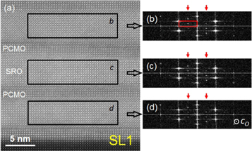
Figure 2. High-angle annular dark-field micrograph of SL1 with fast Fourier transforms (FFTs) acquired across individual SRO layers. The patterns shown in (b), (c) and (d) are the FFT patterns of the SRO layers labeled b, c, d on the HAADF-STEM image in (a). The FFT patterns taken on the various SRO layers showed clear spots corresponding to orthorhombic structure with the [001] (cO) direction as marked in the bottom right corner of (d) (i.e. parallel to the viewing direction). Only the central quarter of the FFTs is shown for better illustration of the spots corresponding to the orthorhombic structure.
Download figure:
Standard image High-resolution imageTo this end we performed high resolution HAADF-STEM and made Fast Fourier transforms (FFTs) of images in small areas (about 15 × 4 nm2) of the individual SRO layers. Figure 2 summarizes the main findings of our analysis of the FFT patterns acquired across several SRO individual layers of SL1 (as imaged by HAADF-STEM in figure 2(a)). All three FFTs taken on areas of SRO layers labeled b, c and d in figure 2(a) exhibit the same spots. The spots whose positions are marked by the red arrows corresponded to oxygen octahedral tilts (see supplementary material, in particular figures S1(a) and S2 for details). The primary pseudo-cubic unit cell of the reciprocal lattice is shown as marked by the red rectangle in figure 2(b). We note here that we increased the lateral width of the windows for FFTs artificially in order to improve the signal to noise ratio, so that the spots marked by the red arrows can be better visualized. The PCMO layers of SL1 were too thin to obtain measurable FFTs such as for the SRO layers.
We performed the same analysis for SL3 and the results are shown in figure 3. In contrast to the SRO layers of SL1, the FFTs of the SRO layers of SL3 did not exhibit the spots corresponding to the oxygen octahedral tilts (see figures 3(d) and (e)). These spots, as marked by the white ellipses in figure 3(b) were however exhibited by the FFTs made on PCMO layers (see figures 3(b), (c), (f) and (g)). We concluded that the oxygen octahedral tilts were much suppressed in the SRO layers of SL3 as compared to the SRO layers of SL1. This is a strong indication that the SRO layers of SL3 have tetragonal structure or a heterogenous structure with larger oxygen octahedral tilts next to the interface with the orthorhombic PCMO layers and with suppressed tilts in the core of the layers. More details on the structure of the superlattices are discussed in the supplementary material, where we analyzed the octahedra tilt angles in SL3 and the detection and type of orthorhombic domains for both SL1 and SL3 (see the supplementary figures S3–S9).
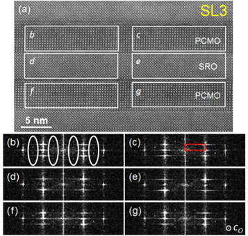
Figure 3. High-angle annular dark-field micrograph of SL3 with fast Fourier transforms (FFTs) acquired across individual SRO and PCMO layers. The FFT patterns shown in (b) to (g) correspond to the images in the areas marked by white rectangles on the HAADF-STEM image in (a) and labeled b to g. The spots corresponding to the orthorhombic structure with the [001] axis (cO) parallel to the viewing direction (i.e. those marked by ellipses) are very weak or even invisible in SRO but are well visible for the PCMO. Only the central one quarter of the FFTs is shown for better illustration of the spots corresponding to the orthorhombic structure.
Download figure:
Standard image High-resolution imageThe tetragonal structure stabilized at RT in SRO layers in SL3 is not as surprising, as it was reported that bare epitaxial SRO films grown on SrTiO3(100) substrates exhibit tetragonal structure at RT, if they are thinner than about 17 pseudo-cubic unit cells (uc) [22]. This was attributed to strong suppression of oxygen octahedra tilts, because of the epitaxial growth on cubic SrTiO3 substrates with undistorted TiO6 octahedra. The suppression of the tilts was expected to be more effective the thinner the SRO films are. Recently, structural data were reported for ultrathin SRO films grown on SrTiO3(100) substrates, where an 8 uc thick SRO layer was imaged by annular bright field STEM and the oxygen octahedral tilt angles were monitored across the layer [23]. This allowed the observation that the first 3–4 uc of SRO next to the substrate had much larger tilts than the top monolayers. This means the structure of the SRO layer is heterogeneous, being more orthorhombically-distorted next to the substrate and tetragonal-like away from the substrate.
Theoretical calculations concluded that the energetically most favorable tetragonal phase of SRO epitaxial films under strain is the I4/mcm phase, characterized by a Glazer [24] tilt pattern  (showing fundamental pseudo-cubic reciprocal lattice for all three axes). This phase was also found to be lower in energy than the orthorhombic Pbnm phase with out-of-plane oriented unit cell in the range from compressive to tensile strains of −2.1% and +3.8% [25].
Tetragonal structure was reported also for epitaxial SRO films grown on orthorhombic GdScO3(110) and NdGaO3(110) substrates [19, 26], on GdScO3-buffered SrTiO3(100) [27] and for oxygen-deficient epitaxial SRO films grown on SrTiO3(100) [28].
4. Hall effect
4.1. Influence of the crystal structure
The Hall effect of orthorhombic [19, 29–32] and tetragonal [19, 32, 33] SRO films was studied before. The anomalous Hall constant of orthorhombic SRO is negative at low temperatures, changes sign at a temperature sensitive to structural quality, but typically between 100 and 125 K, and dominates the Hall effect also well above the Curie temperature [31]. The anomalous Hall constant of tetragonal SRO is positive at all temperatures. This is an experimental result that has yet to be theoretically understood.
The Hall resistivities of superlattices SL1 and SL3 are shown in figure 4. The Hall resistivity of SL1 had the typical field- and temperature dependence characteristic of orthorhombic SRO [29, 30, 32], whereas that of SL3 was characteristic of tetragonal SRO [19, 32, 33]. At low fields the Hall resistivity loops appeared to follow the magnetization loops, i.e. the Hall resistivity ρyx contained both an ordinary and an anomalous contribution with Hall constants RH and RS:  , with applied magnetic field H, magnetization M and vacuum permeability μ0. For a first characterization of the data the saturation Hall resistivity ρyx,S was defined by the extrapolation of the linear high field region to zero field; this is indicated in figure 4(a). The saturation Hall resistivity is given by the product between the anomalous Hall constant RS and the saturation magnetization MS:
  . In case of superlattice SL3 the linear field dependence in an intermediate field range was used for extrapolation, since the Hall resistivity showed a strong curvature in the high field range that we attributed to spin canting due to the antiferromagnetic coupling between SRO and PCMO layers. It has to be kept in mind that the PCMO layers are insulating, and therefore the Hall effect arises only from the SRO layers.

Figure 4. Hall effect of superlattices (a) SL1 and (b) SL3 at selected temperatures. The lines indicate the extrapolation of the high field behavior to zero field.
Download figure:
Standard image High-resolution imageThe saturation Hall resistivity ρyx,S is shown as a function of temperature in figure 5(a) for a variety of SRO films and superlattices containing SRO layers. Whereas the ρyx,S data of orthorhombic SRO films and SrRuO3/SrTiO3 superlattices were rather similar and negative at low temperatures, the Hall resistivity of the tetragonal sample was positive at all temperatures. The data of superlattices SL1 and SL3 were in-between the two extremes, with the data of superlattice SL1 being closer to orthorhombic and those of superlattice SL3 being closer to tetragonal symmetry. This is in agreement with the structural data discussed in section 3.

Figure 5. (a) Comparison of saturation Hall resistivity of orthorhombic 40 nm (OF40) and 5 nm (OF5) SRO films, orthorhombic SRO layers in SRO/STO superlattices (SLSTO1: [4.5 nm SRO/1.5 nm STO]15, SLSTO2: [2.5 nm SRO/3.6 nm STO]15), the PCMO/SRO superlattices (SL1 and SL3) and a 40 nm tetragonal (TF40) SRO film. (b) Anomalous Hall constant RS as a function of resistivity. The anomalous Hall constant RS was determined by dividing the saturation Hall resistivity  by the magnetization values measured in a magnetic field of 0.1 T.
Download figure:
Standard image High-resolution imageScaling laws between anomalous Hall constant RS and longitudinal resistivity ρ were often reported [34] with a linear scaling indicating a skew scattering [35, 36] and a quadratic scaling indicating a side-jump [37] scattering mechanism. The scaling of RS versus ρ is shown in figure 5(b) for the same SRO samples. As a trend, with increasing tetragonality the longitudinal resistivity increased and the anomalous Hall constant increased and changed sign. There is consensus that the anomalous Hall effect in orthorhombic SrRuO3 is dominated by a Berry-phase induced intrinsic Hall resistivity mechanism [6, 7, 38]. The anomalous Hall constant of tetragonal films might be dominated by the side-jump contribution [38], but this is still under debate.
4.2. Field dependence of the Hall resistivity
In this section the detailed field dependence of the Hall effect is discussed, since this yields insight into the possible presence of topological contributions. A comparison between Hall resistivity and magnetic moment is shown in figure 6 for superlattice SL1 and temperatures up to 150 K with the Hall resistivity in red (left axis) and the magnetization in blue (right axis). The high field Hall resistivity was linear in magnetic field; this linear contribution was subtracted to extract only the anomalous Hall effect contribution. At all temperatures the Hall effect and magnetization switching occurred at the same magnetic fields. The field dependence of the magnetic moment had the shape of an easy-axis hysteresis curve superimposed on a ferromagnetic contribution with gradual field dependence characteristic for the weakly ferromagnetic PCMO layers [16]. The field dependence of the Hall resistivity changed in character with increasing temperature. At low temperatures up to about 50 K the Hall resistivity had the shape of a hysteresis curve; at 10 K overshoot loops above the coercive field appeared. At higher temperatures the Hall resistivity had a peak or even a double peak structure close to zero field. This is reminiscent of the signature of a topological Hall effect contribution [3, 10, 13].
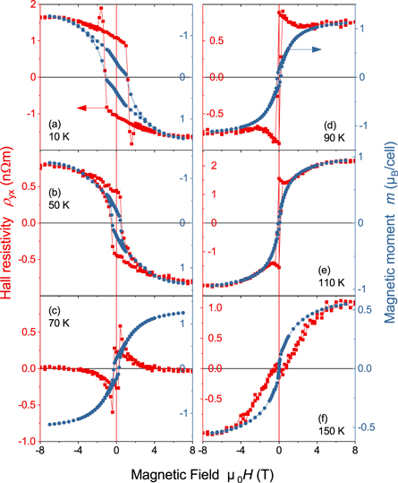
Figure 6. Comparison of Hall resistivity (left scale) and magnetic moment (right scale) of superlattice SL1 at temperatures between 10 and 150 K. Note that in panels (a) and (b) the magnetic moment axis is inverted.
Download figure:
Standard image High-resolution imageA similar comparison between Hall resistivity and magnetic moment is shown in figure 7 for superlattice SL3 and temperatures up to 150 K, again with the Hall resistivity in red (left axis) and the magnetization in blue (right axis). Up to 90 K the Hall resistivity curves had an additional peak in the reverse hysteresis branch after the magnetic field had crossed zero; the field direction is indicated by the black arrows in figure 7(a). This additional peak had no corresponding trace in the magnetic moment hysteresis curve. This is reminiscent of a topological Hall effect signature [3, 10, 13].
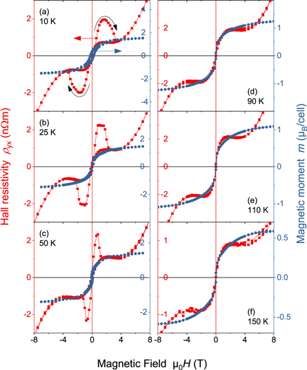
Figure 7. Comparison of Hall resistivity (left scale) and magnetic moment (right scale) of superlattice SL3 at temperatures between 10 and 150 K.
Download figure:
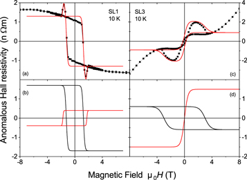
Standard image High-resolution imageIt is tempting to relate the peculiar field dependence of the Hall resistivity to a topological Hall effect contribution arising due to non-trivial scalar spin chirality. The comparison between superlattices SL1 and SL3, especially between the field dependent Hall effect data at 10 K, shows that there is a significant difference between the superlattices. Whereas SL1 has a Hall effect mainly characteristic of orthorhombic SRO, the Hall resistivity of SL3 resembles more that of a tetragonal SRO film. This is consistent with the structure data and the evolution of the anomalous Hall constant with symmetry shown in figure 5(b). Therefore we propose that the observed Hall effect is a superposition of two contributions, each from sub-layers of either orthorhombic or tetragonal symmetry. We simulated Hall resistivity curves for each superlattice by adding a negative and a positive Hall contribution, see figure 8. As a technical detail, the Hall resistivity curves were modeled by ![$\tanh [(H\pm {H}_{C})/{\rm{\Delta }}H]$](https://content.cld.iop.org/journals/2515-7639/2/3/034008/revision2/jpmaterab1aefieqn5.gif) functions with appropriate parameters for the various sub-loops. Detailed agreement cannot be expected, since the antiferromagnetic interlayer coupling was not taken into account. In case of superlattice SL1 this simulation was consistent with the data at all temperatures, when Hall resistivity loops with similar coercivities, but different signs of the anomalous Hall constant were used, see figures 8(a) and (b) for the 10 K data. In contrast, in case of superlattice SL3 good agreement between simulated curves and data was achieved using one hysteresis loop with large coercivity and negative anomalous Hall constant and a second loop with vanishing coercivity and positive anomalous Hall constant, see figures 8(c) and (d). The latter scenario is consistent with the presence of a tetragonal layer core with c-axis along the substrate normal and an orthorhombic layer shell, as also indicated by the structural investigations in section 3. The appearance of a second Hall resistivity loop with positive anomalous Hall constant and large coercivity in superlattice SL1 might be explained by the presence of tetragonal SRO domains with the c-axis in plane. This scenario was not excluded by the structural analysis in section 3. The simulation results were in accordance with recent proposals for the Hall resistivity in SrRuO3/SrIrO3 samples and ultrathin SrRuO3 grown on NdGaO3(110)O substrates [39, 40].
functions with appropriate parameters for the various sub-loops. Detailed agreement cannot be expected, since the antiferromagnetic interlayer coupling was not taken into account. In case of superlattice SL1 this simulation was consistent with the data at all temperatures, when Hall resistivity loops with similar coercivities, but different signs of the anomalous Hall constant were used, see figures 8(a) and (b) for the 10 K data. In contrast, in case of superlattice SL3 good agreement between simulated curves and data was achieved using one hysteresis loop with large coercivity and negative anomalous Hall constant and a second loop with vanishing coercivity and positive anomalous Hall constant, see figures 8(c) and (d). The latter scenario is consistent with the presence of a tetragonal layer core with c-axis along the substrate normal and an orthorhombic layer shell, as also indicated by the structural investigations in section 3. The appearance of a second Hall resistivity loop with positive anomalous Hall constant and large coercivity in superlattice SL1 might be explained by the presence of tetragonal SRO domains with the c-axis in plane. This scenario was not excluded by the structural analysis in section 3. The simulation results were in accordance with recent proposals for the Hall resistivity in SrRuO3/SrIrO3 samples and ultrathin SrRuO3 grown on NdGaO3(110)O substrates [39, 40].
Figure 8. Hall effect of superlattices (a) SL1 and (b) SL3 at 10 K (data points) and simulated curves as described in the text. In (c) and (d) the orthorhombic and tetragonal contributions making up the simulated curves are shown individually.
Download figure:
Standard image High-resolution image
5. Conclusion
Measurements on two Pr0.7Ca0.3MnO3/SrRuO3 superlattices showed structural modifications of the SRO layers that varied with the thickness of the PCMO layers. Especially in superlattice SL3 with the thicker PCMO layers, the SRO layers had tetragonal symmetry at the layer core with a c-axis parallel to the substrate normal, and orthorhombic symmetry close to the interfaces, where the oxygen octahedra had larger tilt angles. Both superlattices showed signatures in the field dependence of the Hall resistivity that were reminiscent of a topological Hall effect. Moreover, the anomalous Hall constant of superlattice SL3 was positive in the temperature range measured, from 10 to 200 K. In agreement with the structure data this behavior is characteristic of SRO layers with tetragonal symmetry [19, 32, 33]. On the other hand, superlattice SL1 showed more conventional Hall effect behavior consistent with orthorhombic SRO layers, albeit also with additional field dependent features.
Since superlattice SL3 showed clear structural changes compared to superlattice SL1, we attribute the Hall effect signatures shown in figures 7(a)–(c) not to the presence of complex magnetization textures due to the antiferromagnetic interlayer coupling, since this is present in both samples [16], but as arising from a superposition of Hall signals from tetragonal- and orthorhombic-like regions of the SRO layers. This is consistent with the simulations in figure 8, with the sign of the anomalous Hall effect and with the anisotropy of the Hall loop that is characteristic for a magnetic hard axis along the substrate normal. Similarly, the field dependence of the Hall resistivity of superlattice SL1 at all measured temperatures can be understood as a rising from the superposition of two Hall loops, both with characteristic easy-axis loop shape, but with alternate signs of the anomalous Hall constant. This result indicates that the tetragonal-like SRO regions in sample SL1 had an in-plane c-axis.
Overall, these results show that the anomalous Hall effect can therefore be used as a first marker for the detection of complex structural patterns (e.g. structural domains, inhomogeneous oxygen octahedra tilts) in heterostructures based on SrRuO3 layers.
Acknowledgments
We thank Professor Dr C-L Jia (FZ Jülich) for fruitful discussions and advice and Dr Xiang Chen (RWTH Aachen University) for the FIB preparation of the specimens. MZ acknowledges funding by the Deutsche Forschungsgemeinschaft (DFG, German Research Foundation)—Projektnummer 31047526—SFB 762, project B5. IL-V acknowledges DFG for financial support through project LI 3015/3-1—Projektnummer 335038432.