
Abstract
A detailed analysis of micro- and nanoantennas is crucial for enhancing the performance of photodetectors in the mid- and far-infrared (IR) region. In contrast to the rapid progress in IR detectors based on nanodevices, the local nanoscale properties of antennas for the purpose of near-field coupling with these detectors have not been well investigated. In this work, we fabricated and studied a logarithm-spiral (log-spiral) antenna with an arm termination, which was designed as a low-loss, wide-band antenna for highly efficient near-field interaction with nanoscale IR detectors. By using a scattering-type near-field optical microscope (s-SNOM) combined with a highly stable quantum cascade laser, we observed a nanoscale spatial distribution of amplitudes generated via IR illumination on the antenna surface. Experimental and simulated results revealed a clear dependence on IR-light polarization corresponding to the rotationally symmetric structure of the spiral antenna. Furthermore, phase mapping measurements indicated a π reversal of the out-of-plane phase between two adjacent antenna probes regardless of polarization direction, providing a possibility of efficient near-field coupling with nanoscale detectors. These results demonstrate that s-SNOM imaging offers a powerful tool for gaining useful information regarding mutual coupling between optical antennas and nanostructures.
Export citation and abstract BibTeX RIS

Original content from this work may be used under the terms of the Creative Commons Attribution 3.0 licence. Any further distribution of this work must maintain attribution to the author(s) and the title of the work, journal citation and DOI.
The development of highly sensitive photodetectors in the mid- and far-infrared (IR) region is increasingly required in diverse areas, including security checks, chemical spectroscopy and imaging, environmental estimation, and medical care [1, 2]. Enhancement of the detection sensitivity is particularly critical in advanced fields such as single-molecule IR measurements and cancer cell imaging. Although the use of nanoscale devices in building blocks of IR detectors has improved detector performance, most of these detectors must be coupled with appropriate antennas because the sensing area (nanometre scale) of the detectors is much smaller than the received wavelengths (micrometre scale) [1, 3]. Therefore, micro- and nanoantennas currently play an important role in the efficient transfer of power of irradiated waves to carriers confined in the nanostructures of the detectors. There have been several related studies on optimization of antenna designs [4, 5] and exploration of antenna materials [6, 7]. Among various antennas, planar antennas [8] such as the bow-tie antenna, the logarithm periodic antenna and the logarithm-spiral (log-spiral) antenna are widely used to couple optical fields with detectors in a broad frequency band [9–11]. Though these previous studies provided important information on IR antennas, the nanoscale local properties of electric field and phase for bow-tie probe combined with spiral structures have not been fully investigated and understood, especially in terms of incident IR polarization dependence.
A scattering-type near-field optical microscope (s-SNOM) is a powerful tool for studying the optical properties of nanostructures [12–15]. Measurements of mutual near-field interaction between a tip and sample surface provide information about specific properties derived from a sample's local surface state. Using this method, previous studies have obtained results for plasmon dynamics of plasmonic structures [16, 17] and graphene [18, 19], chemical composite mapping of polymers [20], distribution imaging of conductivity differences in semiconductor nanotransistors [21], and electric field distributions in nanoscale waveguides [22] and antennas [23, 24].
In this work, we present near-field imaging of a log-spiral antenna with a bow-tie probe in which the spiral arms are terminated. As depicted in the lower inset of supplementary figure 1, in this arm-terminated structure, the outer end parts of the spiral arms become gradually narrow and are terminated at one point. This design is intended for use as a low-loss antenna for integration with nanoscale IR detectors. Theoretically, the log-spiral antenna, which is a type of self-complementary antenna, has an almost constant input impedance over a wide frequency range because AC currents are continuously concentrated on different areas of the spiral arms [8]. Thus, the log-spiral antenna is useful for broadband detection. While the light coupling efficiency of this type of antenna is thought to be strongly influenced by the design of the spiral arms' end, the details remain unclear. We observed that a log-spiral antenna with an arm termination (black curve in supplementary figure S1 is available online at stacks.iop.org/JPCO/2/105004/mmedia) can serve as a higher-efficiency antenna than a non arm-terminated antenna (red curve in supplementary figure 1). This suggests that the arm termination allows the antenna surface current to decrease smoothly along the arms without abrupt terminations, thereby reducing reflections and disturbances. Nevertheless, detailed near-field investigations of a log-spiral antenna with an arm termination have not been performed to date.
This paper reports on a study of the nanoscale spatial distribution of the amplitudes and phases of an arm-terminated log-spiral antenna in the IR region. Using measurements and simulations of IR-polarization dependence, we revealed rotationally symmetric distributions of electric fields on the antenna surface that originate from the spiral structure. IR phase measurements showed that a π phase reversal occurs between two adjacent probes at the centre of the log-spiral antenna for any polarization direction. This feature is in strong contrast to the behaviour of a simple bow-tie antenna and a dipole antenna, which exhibit a π phase reversal only for a perpendicular polarization direction relative to the two opposite metallic probes. Furthermore, phase mapping resolved between the in-plane and out-of-plane distributions indicated that the π phase reversal occurred only for the out-of-plane distribution, suggesting that closed curves of electric force lines are bridged between the two probes at the spiral antenna centre. This behaviour offers a strong possibility of efficient near-field coupling with IR detectors integrated at the spiral centre.
The details of our experimental setup are schematically shown in figure 1. The s-SNOM system used here is based on a tapping-mode atomic force microscope (AFM). We used Si tips coated with platinum as the AFM cantilever. Vertically polarized (p-polarized) mid-IR laser beams were focused via a 45° parabolic mirror, and the cantilever and antenna were illuminated by the mid-IR beams at an angle of 30° relative to the antenna surface. The mid-IR beam was scattered through near-field interaction between the cantilever tip and the antenna surface, and the scattered light was sensed by a mid-IR detector. The intensity of the incident laser light was modulated in synchronization with the vertical oscillation of the cantilever tip (oscillation frequency Ω ∼ 250 kHz). By measuring the signal at a high-order harmonic frequency nΩ (n is an integer), background contributions of the IR beam can be easily suppressed [25]. For all experiments, we plotted the results for second-order harmonics (n = 2), because the data for n > 2 exhibited similar features. Moreover, the use of a pseudoheterodyne technique based on a Michelson interferometer allowed us to measure phase distributions simultaneously [25].
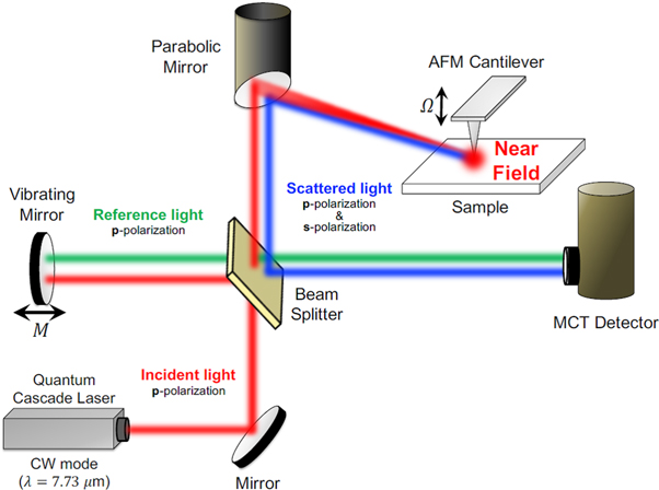
Figure 1. Schematic view of the s-SNOM system equipped with a QCL.
Download figure:
Standard image High-resolution imageAs an illumination source for the s-SNOM, we used a mid-IR quantum cascade laser (QCL) at a wavelength of 7.73 μm with vertical polarization and in continuous wave mode (see figure 2(a)). The QCL has a narrower spectral line width and a higher stability of output power when compared to the CO2 gas laser commonly used for the mid-IR s-SNOM. As a result, we obtained an approximately one order of magnitude higher signal-to-noise (S/N) ratio than that obtained using the CO2 laser. Figure 2(a) also depicts the propagation direction of the mid-IR beam (red arrow) and the polarization direction of the mid-IR electric field (black two-way arrow) relative to the sample surface. We define the angle of the mid-IR incidence θ as the angle between the propagation direction of the incident light and the long axis of the bow-tie probe (x-axis).
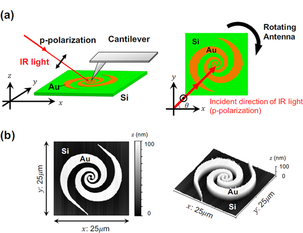
Figure 2. (a) Sketch of the s-SNOM measurement setup. The red arrows show the propagation direction of the incident IR source light, and the black two-way arrows indicate the polarization direction of the IR electric fields. θ denotes the angle between the x-axis and the propagation direction of the incident IR light. We measured the θ dependence of the near-field IR images by rotating the sample while keeping all optical components stationary. (b) Topography images of the studied arm-terminated log-spiral antenna with a bow-tie probe. Two-dimensional (left) and three-dimensional (right) images are displayed.
Download figure:
Standard image High-resolution imageThe antenna consists of a 100 nm-thick Au film deposited on a Si substrate by electron beam evaporation, with an outer diameter of 20 μm (figure 2(b)). Figure 2(b) shows a topographic image of the antenna obtained by simultaneous AFM measurements. As shown in figure 2(b), this log-spiral antenna has a bow-tie probe at the centre, and the end of the spiral arm is terminated. The turn number of the antenna is 1.5.
We first investigated the effect of the rotationally symmetric structure of the log-spiral antenna. Figure 3(a) displays near-field images of IR field amplitudes when the antenna was rotated by θ = 45°, 135°, 225°, and 315° such that the incident direction of the mid-IR beam was exactly opposite relative to the antenna centre between θ = 45° and 135° and between θ = 225° and 315°. For clarity, the images for θ = 225° and 315° were rotated by 180° and are re-displayed on the right-hand side of figure 3(b). A comparison between the 45° and 225°–180° directions clearly shows that the two images exhibit similar patterns. This behaviour is consistent with the feature of the rotationally symmetric structure, which is an inherent characteristic of the log-spiral antenna. Similarly, the 135° and 315°–180° directions exhibit similar behaviour, ensuring the rotationally symmetric nature of the spiral antenna and the reproducibility of the measurements performed in this work.
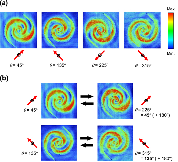
Figure 3. (a) Experimental results for near-field images of the IR electric fields on the antenna for IR polarizations at θ = 45°, 135°, 225°, and 315°. (b) The images for θ = 225° and 315° in (a) are rotated by 180° and are shown again on the right-hand side for comparison with those for θ = 45° and 135°.
Download figure:
Standard image High-resolution imageWe then studied the IR-polarization dependence of the electric fields in the antenna; the near-field amplitude distribution is displayed in the upper panel of figure 4. The antenna was rotated by 45° in a step-by-step manner while leaving the optical components and systems stationary and undisturbed; thus, the polarization angle relative to the antenna surface changed from θ = 0° to θ = 135°. In this way, the near-field signals were not affected by the optical components or systems; thereby, the polarization dependence of the antenna itself was studied. It was observed that as the angle θ varies, the pattern of the electric field distribution rotates accordingly, corresponding to the rotation of the direction of the incident light polarization. (For example, see the areas surrounded by black dashed circles in the upper panel of figure 4). Electric fields were similarly distributed on the antenna for all polarization directions, which is consistent with the features expected for the symmetric structure of the spiral antenna. This result is in strong contrast to the characteristics of a bow-tie antenna and a dipole antenna, which exhibit the generation of strong electric fields only when the polarization is parallel to the long direction of the antenna.

Figure 4. IR-polarization dependence of near-field images of the IR electric fields on the antenna at θ = 0, 45, 90, and 135°. The dashed circles are guides to the eye. The upper and lower panels show experimental and simulation results, respectively. The electric field distribution on the surface of a log-spiral antenna was calculated for IR light with a wavelength of 7.73 μm incident at an angle of 30° relative to the antenna surface, the configuration of which is the same as in the actual experimental setup.
Download figure:
Standard image High-resolution imageWe performed numerical simulations of the surface electric field distributions for the present antenna using the finite-difference time-domain method. The antenna structure for the simulation is the same as that used in the experiments. The dependence on the incident light polarization is shown in the lower panel of figure 4. In this simulation, we plotted the spatial distribution of the electric fields generated by vertically polarized IR light with a wavelength of 7.73 μm, where the incidence angle relative to the antenna surface was set to 30°. These conditions are the same as those of the above experiments. The simulation results indicate that the patterns of the electric field distributions rotated according to the variation in the polarization direction of the incident IR light. These results reproduce the general tendency of the near-field patterns observed with the s-SNOM, as shown in the upper panel of figure 4, indicating that the electric field distributions observed with the s-SNOM in this work correspond to the characteristics of the antenna itself.
To examine the gap region between the two bow-tie probes (schematically shown in figure 5(a)) in detail, we performed phase mapping measurements. Figure 5(b) displays the phase distributions of the bow-tie probes, indicating a phase reversal at the centre of the bow-tie probes for all polarization directions. For clarity, figure 5(c) displays line profiles for the centre of the bow-tie probe along the x-axis of figure 5(a). By fitting the line profiles with a polynomial of the third order and subtracting higher-order polynomials, we removed the undesired noise that affected the phase data. We found that the phase reversed by π between the two opposite probes at the spirals' end and that this π phase reversal occurred for all polarization directions. It is known that a bow-tie antenna alone has a specific polarization dependence in which its phase jumps by π between the two probes only for the polarization parallel to the two probes. Hence, the results obtained here indicate that when a bow-tie antenna is combined with a spiral structure, the antenna is free of the linear polarization dependence. The simulation results (supplementary figure S2) also show a π phase reversal, supporting the s-SNOM results.
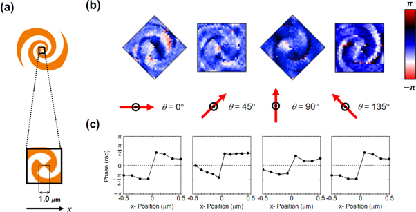
Figure 5. (a) Sketch of the bow-tie probe at the centre of the spiral antenna, where near-field phase measurements were performed. (b) Near-field phase distributions in the bow-tie probe for θ = 0, 45, 90, and 135°. (c) Line profiles in the centre of the bow-tie probe along the x-axis.
Download figure:
Standard image High-resolution imageFurthermore, we separately visualized the in-plane and out-of-plane phase distributions in the antenna centre region. As depicted by the experimental setup in figure 6, the polarization of the reference light that is coupled to the scattered light was transformed into a combination of s-polarized light and p-polarized light through the use of a quarter-wave plate; consequently, the interferometric signal contains information about both the in-plane and out-of-plane light fields. These two fields are selectively detected by the polarizer placed in the front of the detector.

Figure 6. Illustration of the experimental setup for separately imaging in-plane and out-of-plane phase distributions.
Download figure:
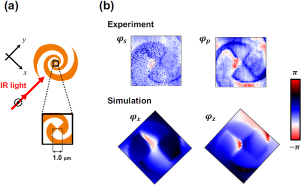
Standard image High-resolution imageWe used the above setup for separate near-field imaging of in-plane and out-of-plane phase distributions in the bow-tie probe of the spiral centre, as shown in figure 7(a). Figure 7(b) presents separate observations of the out-of-plane and in-plane phase distributions. The out-of-plane distribution indicates that a π phase reversal occurs at the gap of the two probes, whereas no such π phase jump is seen for the in-plane distribution. These findings suggest that closed curves of electric force lines are linked over the two probes, thereby offering a possibility that IR fields can be effectively coupled regardless of the linear light polarization when integrated with nanoscale IR detectors at the gap region of the two bow-tie probes.
Figure 7. (a) Enlarged view of the bow-tie component at the centre of the antenna, wherein near-field phase mapping was performed using the setup shown in figure 6. (b) Near-field images of the in-plane phase φs and out-of-plane phase φp in the bow-tie probe region of the antenna. Simulated results of in-plane phase φx and out-of-plane phase φz are also displayed in the lower panel.
Download figure:
Standard image High-resolution image
In conclusion, we demonstrated nanoscale near-field mapping of a log-spiral antenna with arm termination in the mid-IR region by using a QCL as the illumination source. The use of a QCL with a single-mode lasing property enabled a clear observation of light-polarization dependence of the amplitude and phase distributions in the spiral antenna with a high S/N ratio. The IR-polarization dependence shows a rotationally symmetric pattern of electric fields consistent with the spiral structure and nature of the antenna. Additional phase mapping measurements revealed a π phase jump between the two opposite probes of the spiral centre for all polarization directions, indicating that electric force lines are bridged over the two probes. These results suggest that the present arm-terminated spiral structure can function as a high-efficiency wide-band antenna suitable for integration with nanoscale IR detectors. Thus, near-field studies of antennas for integration with detectors provide useful information regarding nanoscale coupling with optical fields and provide opportunities for enhancing detector performance in the future.
Acknowledgments
This work was supported in part by the JST-Mirai Program, the Matching Planner Program, and the Center of Innovation Program from the Japan Science and Technology Agency, JSPS KAKENHI Grant Numbers JP16J09937, JP17K19026, JP17H02730, JP16H00798, JP16H00906 and JP18H03766 from the Japan Society for the Promotion of Science, the Murata Science Foundation, and Support for Tokyo Tech Advanced Researchers (STAR).