
Abstract
A parabolic mirror is used for the first time in a wide-angle ellipsometric system to determine the parameters ψ and Δ and the thickness of SiO2 layer naturally grown on Si crystal substrate. Collimated illuminating beam of diameter 20 mm incident on a parabolic mirror is reflected at the Si-SiO2 system to provide wide angle of incidence. The polarization states of points in the illuminated area are determined and the data is analyzed for real-time thickness maps over the measured area of the surface. The thickness of SiO2 layer is found as 3.02 nm with Standard deviation ±0.12 nm. Null ellipsometer is also used at different angles of incidence to check our result and nearly the same thickness value was obtained.
Export citation and abstract BibTeX RIS

Original content from this work may be used under the terms of the Creative Commons Attribution 3.0 licence. Any further distribution of this work must maintain attribution to the author(s) and the title of the work, journal citation and DOI.
1. Introduction
Ellipsometry is an accurate, contactless and non-destructive technique for thin film characterization. Measurements are usually carried with a beam of very small diameter so that results are obtained for a single spot. To measure the lateral distribution of optical properties of the surface, measurements can be carried out point by point by mechanical scanning techniques [1] which are time-consuming work particularly if the surface is of large area. Methods for wide angle of incidence ellipsometry were presented using non-collimated beam [2, 3] or extended source for illumination [4]. In this work, a new imaging ellipsometric system is used to determine the thickness of SiO2 film grown on Si substrate. The surface is illuminated by collimated beam reflected from parabolic mirror providing wide angle of incidence. In this way, different points on the surface are studied at different incidence angles. Measurements are performed at wavelength 632.8 nm with He-Ne laser at three orientations of the analyzer. Results are then analyzed to find the thickness of the SiO2 layer. A null ellipsometer is also used to determine the ellipsometric parameters ψ and Δ to determine the thickness of SiO2 layer. It was intended to use the air-Si-SiO2 system in our work which was extensively studied by different authors to compare our results with previous studies.
2. Experimental
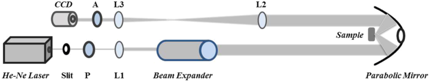
The optical system used for wide angle measurement is a photometric rotating analyzer ellipsometer RAE, figure 1. Light emitted from He-Ne laser source (λ = 632.8 nm) falls on a polarizing prism P oriented at azimuth 45° followed by lens L1 and beam expander. The expanded beam with diameter ∼20 mm falls on the parabolic mirror and is reflected on the Si-SiO2 system at different incidence angles ranging from 44° to 72°. The beam is reflected again to the parabolic mirror and then to the other arm of the ellipsometer. The two lenses L2 and L3 reduce the beam size to be fully accepted by the analyzer A and the sensing area of CCD camera (CMOS EO-1312M monochrome, computer controlled digital camera).

Figure 1. Photometric rotating analyzer ellipsometer RAE ellipsometer setup, P: polarizer, A: analyzer, L1, L2, L3: lenses.
Download figure:
Standard image High-resolution imageEllipsometry measures the change in the polarization state of reflected light. Properties of the reflecting surface are obtained by analysis of polarization changes. The measured parameters are ψ and Δ where tan ψ is the change in amplitude ratio and Δ is the change in phase. The general equation of ellipsometry relates the complex reflectance ratio ρ to the parameters ψ and Δ by [5]

Three measurements with the analyzer A set at 0°, 45° and 90° are sufficient to determine the parameters ψ and Δ with P fixed at azimuth 45° [6]. The intensity at the detector is given as [7]

Where α2 is the analyzer orientation and s0, s1 and s2 are the Stokes parameters defined as [5]


Where Ep and Es are the parallel and perpendicular components of the electric vector and the asterisks denote complex conjugates. The intensity at different analyzer orientations are given from (2) as


Also, the intensity at the detector is related to the ellipsometric parameters ψ and Δ by the relation [7]

Comparing equations (2) and (5) we get


Replacing rp and rs in equation (1) by the reflection coefficients of the three-phase optical system, figure 2, we get

Where i = √−1, β is the phase change due to light propagation through medium 1 and


Figure 2. The reflection coefficients of the three-phase air-silicon dioxide-silicon optical system.
Download figure:
Standard image High-resolution imageSubstituting with the values of n0 (=1) and n1 (=1.4570) and n2 (3.8827 − i 0.0196), the angles θ0, θ1 and θ2 are calculated using Snell's law

with θ0 ranging between 44° and 72°.
We used the value n1 = 1.457 for the refractive index of SiO2 since ellipsometry cannot determine both the refractive index and thickness for ultrathin films, nor can it effectively separate the quantities. Noting that in [8] it is stated that: 'errors in the fixed SiO2 index values translate into errors in film thickness, but these thickness errors are usually only a fraction of a monolayer for native oxides. This level of error traditionally has been acceptable in semiconductor manufacturing'.
Equation (5) could be written in the form

where A = ρ12,πρ01,σρ12,σ, B = ρ01,πρ01,σρ12,σ + ρ12,π, C = ρ01,π, D = ρ01,πρ12,πρ12,σ, E = ρ01,πρ12,πρ01,σ + ρ12,σ, F = ρ01,σ and X = exp (−i2β).
Solving for X and substituting in the expression

we get the required film thickness d.
To check the result obtained by the photometric wide-angle ellipsometer, the same three-phase system was investigated by null ellipsometry at angles of incidence ranging between 45° and 70° in steps of 5°, figure 3. Light from the same He-Ne source falls on the polarizer P followed by a quarterwave phase plate C oriented with its fast axis at 45°. The beam is then incident on the three-phase sample S at the selected angles of incidence. The beam reflected from the sample passes through the analyzer A and is detected by the detecting system D (photomultiplier, power supply and millivolt-meter). P and A are simultaneously adjusted for extinction and the ellipsometric parameters ψ and Δ are calculated from the relations


where (P0, A0) and  are the two extinction pairs and


With ψ and Δ obtained, the thickness is obtained with the same procedure used in photometric ellipsometry.

Figure 3. Null ellipsometer, P: polarizer, A: analyzer, C: compensator.
Download figure:
Standard image High-resolution image3. Results and discussion
Figure 4 represents the reflectances Rp and Rs of SiO2 showing Brewster angle at ∼56° in agreement with published data. Intensity distributions at the three analyzer settings (0°, 45° and 90°) are presented in figures 5(a)–(c).

Figure 4. Reflectances Rp and Rs versus angles of incidence.
Download figure:
Standard image High-resolution image
Figure 5. Intensity distribution for the three analyzer orientations (a) 0°, (b) 45° and (c) 90°.
Download figure:
Standard image High-resolution imageThe ellipsometric parameters ψ and Δ for different angles of incidence using the wide angle of incidence system shown in figure 1 are presented in figures 6(a), (b). Results were obtained using MATLAB software. The thickness of SiO2 film as calculated at different angles of incidence is shown in figures 7(a), (b) and is found to range between 2.54 nm and 3.16 nm with a mean value of 3.02 nm and we concluded that

where the value 0.12 nm is the standard deviation of the mean.

Figure 6. The ellipsometric parameters ψ and Δ (a), (b) at different angles of incidence obtained from wide-angle of incidence ellipsometry. The continuous lines are results from null ellipsometric measurements.
Download figure:
Standard image High-resolution image
Figure 7. Thickness of SiO2 film at different angles of incidence obtained from wide-angle of incidence ellipsometry. The continuous line in figure 7(a) is from null ellipsometric measurements.
Download figure:
Standard image High-resolution image
Measurements are also performed using null ellipsometer at the same wavelength λ = 632.8 nm and at angles of incidence ranging between 45° and 70° in steps of 5°. The quarterwave plate C is set with its fast axis oriented at 45° and the two polarizing prisms P and A are simultaneously rotated for extinction. Results for the calculated parameters ψ and Δ are presented in figures 6(a), (b) with continuous lines. The thickness of the film as calculated from null ellipsometric measurements is

and is shown in figure 7(a) by the continuous line which is in high agreement with value obtained by wide angle ellipsometry. The value 0.08 is the standard deviation of the mean.
Our results for ψ, Δ and thickness values obtained from both methods and from previous work [8] show high agreement confirming the success of our method for wide angle ellipsometry using parabolic mirror which provides wide range of angles of incidence. Small differences between results in equations (15) and (16) arise probably from alignment errors or local non-uniformity of the film. In comparison with mechanical scanning methods where measurements are performed at each angles separately, our method is time-saving and allows for measurements in a wide range of angles. Also, using parabolic mirror instead of a lens in wide-angle ellipsometry is advantageous in that a parabolic mirror eliminates spherical aberration providing a sharp and clear image which is not the case with spherical lens. Besides, a single-shot measurement reduces 1/f noise (shot noise) to a large extent and makes it negligible in comparison with mechanical scanning methods [9].
Perturbation of polarization from angle-dependent reflection from the parabolic mirror is of negligible effect on the results. This is concluded on the basis of agreement between the results of the parameters ψ and Δ (figure 6) with those obtained from null ellipsometry and also results for the thickness of SiO2 layer from both methods (figure 7). A final note is that it is true that the parabolic mirror introduces phase shift which cannot be separated from the phase shift introduced by the studied system. However, since our measurements are relative, the presence of the mirror has no effect on the results [2, 10].