

Abstract
A major sustainability concern of manufacturing industries is indiscriminate use of lubrication, energy consumption, and allied cost. To avoid such kind of situation and to improve the product quality, sustainable manufacturing concept has been widely used. One of the popular technique is the use of Minimum Quantity Lubrication (MQL) as a working fluid to improve the product performance. Diamond burnishing under MQL environment is an exceptional technique to obtain the improved surface integrity of the material without affecting operator health and environmental aspects. In this work, the impact of control factors on the surface integrity characteristics namely surface roughness, surface topography, surface hardness, surface morphology, residual stress and subsurface hardness of 17-4 PH stainless steel have been studied under MQL environment by using a novel modified tool. It was ensured that minimum surface roughness of 0.05 μm and maximum surface hardness of 405 HV had been achieved. Improved surface finish and surface hardness were obtained for a diamond sphere radius of 4 mm and 3 mm respectively under optimal diamond burnishing conditions. The obtained investigational results confirm that a novel modified tool was successfully implemented to enhance the surface integrity characteristics under the MQL environment.
Export citation and abstract BibTeX RIS
1. Introduction
Technological quality of the component can be estimated by an important factor known as surface quality. Wear resistance and fatigue strength are the two major factors which are influenced by the surface roughness of the component. It is highly impossible to generate a flat surface by machining because surfaces will always have irregularities. In order to obtain super finished surface, some of the secondary finishing operations have to be performed such as polishing, honing, lapping etc. One of the most relevant and popular technique to improve the surface characteristics of the material is burnishing. It is a chipless finishing process in which the peaks of the material spread out enduringly to fill the valleys at a suitably applied force on the material [1]. It has additional advantages namely improving fatigue strength, corrosion resistance, and surface hardness along with the induction of compressive residual stresses on the material [2]. Diamond burnishing is a process where the tool consists of a diamond tip which will be in contact with the workpiece during burnishing operation. A superior surface finish can be attainable by using a diamond burnishing tool.
17-4 PH stainless steel is a special type of precipitation hardenable martensitic stainless steel which consists of martensite and along with a small quantity of austenite. Attributable to its high ductility property and low thermal conduction rate it has been categorized under difficult to machine materials [3]. It has a varied range of applications by means of its high strength and exceptional corrosion resistance properties which includes chemical process equipment, marine construction, nuclear reactors, power plants, pump shafts etc. In recent years the critical components which are being used in the aircraft engines have been replaced with 17-4 PH stainless steel in place of titanium alloys and polymeric composite materials because these components will be subjected to high cyclical thermal and mechanical loads. In the meanwhile improved fatigue strength and surface integrity are expected in such kind of heavy duty components [4, 5].
Manufacturing industries are seeking various techniques for reducing the consumption of the coolant/lubricants in the machining process as a consequence of ecological and economic pressures [6]. Lubrication can be treated as a basic method to get rid of the heat produced in the course of metal cutting. Though flood cooling was treated to be a significant lubricant to carry away the heat generated, it was found to be ineffective at higher spindle speeds due to the inefficiency of the lubricant to reach to the critical areas such as a tool-workpiece interface. To overcome the above-mentioned drawbacks faced by the manufacturers, an effective lubrication method known as MQL emerges out as a substitute to flood cooling system. In MQL system, cutting fluid and mixture of air in the form of mist lubrication is supplied to the burnishing zone. The quantity of the lubricant supplied is very small when compared to the conventional type of lubrication method.
Maximov et al [7] performed slide burnishing on AISI 316Ti chromium–nickel steel and obtained an improvement in its surface integrity. Further, the validation was carried out by using FEM analysis. Konefal et al [8] compared the influence of burnishing, polishing and drawing process on the corrosion resistance of X6CrNiMoTi17-12-2 stainless steel. It was seen that the finest corrosion resistance was obtained for a burnished specimen. Korzynski et al [9] explored the impact of chromium coatings performed by slide burnishing and polishing on 42CrMo4 and 41Cr4 steel samples. It was proved that slide burnishing had produced better results in contrast with band polishing without creating technical problems. Okada et al [10] proposed a novel method to burnish Aluminum-based alloy ASTM 2017 by using a roller burnishing process which can perform rolling and sliding. MQL was used as the lubrication during the burnishing process. It was observed that the proposed method was successful in improving its surface integrity. Liska et al [11] investigated the impact of hard turning and diamond burnishing of 100Cr6 hardened bearing steel under MQL condition. The surface roughness was proved to be minimized in comparison with hard turning process. Revankar et al [12] optimized the factors in ball burnishing of Ti–6Al–4 V alloy and the lubricant used was SAE 30 base oil. Turning process was also carried out before performing ball burnishing under MQL environment. It was shown that improved surface finish and surface hardness was achieved for ball burnished sample. Yang et al [13] compared the effect of burnishing on Co–Cr–Mo alloy under cryogenic and dry conditions. It was observed that the enhanced surface modifications were attained with the cryogenic environment. Korzynski et al [14] performed slide diamond burnishing on AZ91 alloy and studied its surface stereometric structure. It was found that slide burnishing is a suitable technique to improve the surface stereometric structure of AZ91 alloy components.
Previous kinds of literature on burnishing shows that major influencing control factors on surface conditions are: burnishing force, burnishing speed, tool material, burnishing feed, and mode of lubrication [15–23]. The temperature formed at the burnishing zone may cause deteriorated surface and it needs to be resolved. The limited research effort has been identified on the literature regarding burnishing under MQL environment. Also, it is very much essential to develop a relationship among MQL, diamond burnishing factors and the surface integrity characteristics to achieve improved functional performance of the product. 17-4 PH stainless steel has abundant applications in key areas and hence there is a necessity of exploring the importance of diamond burnishing on it. In the present study, the surface integrity factors namely surface topography, surface roughness, surface morphology, surface hardness, subsurface microhardness, and residual stress were studied by considering diamond sphere radius, number of tool passes, burnishing speed, burnishing feed and burnishing force as input parameters under MQL environment by using a novel modified tool.
2. Experimental work
2.1. Material
The experimentation was executed on 17-4 PH stainless steel, which has outstanding corrosion resistance and high strength properties. It has a dimension of 150 mm length and 32 mm diameter. The major elements of the material is comprised of Ni-5.33%; Cr-19.29%; Cu-3.67%; Si-0.30%; C-2.49%; S-0.02%; Ta-0.18%, and Fe-Balance. Burnishing is a secondary finishing process and the surface roughness before burnishing is a key factor in enriching the surface finish of the component after burnishing [15, 16]. The surface roughness measured after turning process was observed to be 1.20 μm. Based on authors preliminary investigation on diamond burnishing under MQL environment the process parameters and their respective levels were considered which is as tabulated in table 1. The diamond burnishing set up is as shown in figure 1.
Table 1. Experimental control factors.
| Levels | ||||
|---|---|---|---|---|
| Burnishing process parameters | 1 | 2 | 3 | |
| Diamond sphere radius (r) | mm | 3 | 4 | 5 |
| Burnishing speed (s) | m min−1 | 23 | 78 | 121 |
| Burnishing feed (f) | mm rev−1 | 0.048 | 0.065 | 0.096 |
| Burnishing force (F) | N | 40 | 115 | 190 |
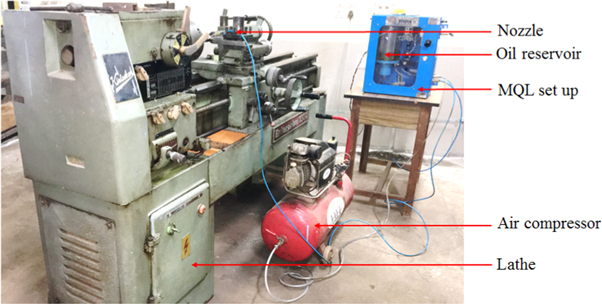
Figure 1. Diamond burnishing and MQL set up.
Download figure:
Standard image High-resolution image2.2. Measurement information
Conventional 'Kirloskar' lathe has been used to carry out diamond burnishing operation. The surface hardness was computed by Vickers hardness tester model 'VM-120'. The surface roughness was noted through 'Mitutoyo Surftest SJ-301'. In order to obtain the accurate results for the responses, an average of three readings has been considered. The surface topography has been obtained by using 'LESTOLS4100' model confocal laser 3D surface tester. Diamond burnished surface morphology was studied by using 'JEOJSM-638OLA' model scanning electron microscope (SEM). Residual stress has been measured by using x-ray diffraction with MGR40P stress measurement system make 'PROTO'. Vickers microhardness tester type 'OMNI TECHMVHS-AUTO' was used to measure the subsurface microhardness after diamond burnishing.
2.3. MQL system
The present study has been carried out under the MQL environment and the setup used is as depicted in figure 1. Coconut oil has been used as a lubricant in MQL set up. The entire setup is comprised of an oil tank of 2 liters capacity and pneumatic air pump to circulate the compressed air. Electronic timer B1DCA-X has been used to adjust the frequency of the oil piston pump. 0.40 cc/stroke is considered to be the discharge rate of the oil. The flow rate of the oil has been fixed to be 70 ml hr−1. To obtain this flow rate the air compressor has been used to compress the oil inside the tank and the flow rate was set to be 4 kg cm−2. An external nozzle has been used to obtain the mist of oil in the burnishing zone. It is flexible and oil can be easily directed to the required area without altering or affecting the burnishing condition.
2.4. A novel modified tool
In the preliminary experimentation, it was observed that a small sphere radius of the diamond tip will improve surface hardness whereas moderate sphere radius would improve surface finish. Hence in the present study spherical diamond tip of radius 3 mm, 4 mm and 5 mm was used. Figure 2 shows a specially designed and fabricated modified tool which has been used to carry out the diamond burnishing experiments. This tool contains two parts. The first one is diamond stem which has been attached to the shank of the tool which is the second part. The stem of the tool contains a spherical diamond tip. The modification has been done in such a way that the stem of the tool can be easily detached from the shank by a button head screw. The movement of the stem will compress the spring which can be used to compute the applied burnishing force. A novel modified tool has the following advantages over the conventional diamond burnishing tools: a newly modified tool has a smaller overhang in contrast with the conventional square shank tool. Heavy-duty springs with an increased number of coils have been used in the tool. Attachment to a conventional lathe or CNC machine is easy because of the extra grip provided with a newly modified tool. Easy to measure the deflection of the spring by means of a dial gauge because of the presence of a dowel pin.
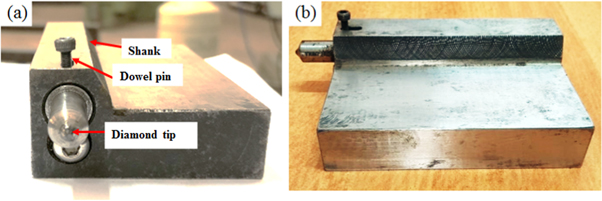
Figure 2. A novel modified tool (a) Front view, (b) Side view.
Download figure:
Standard image High-resolution image3. Results and discussion
In recent years, developing new techniques for improving the surface integrity characteristics in machined components is one of the emerging areas in manufacturing. Heat generation is a common phenomenon encountered during machining of a component, and a lubricating media is necessary to significantly reduce the formation of higher temperature formed at the burnishing zone. Reduction of the temperature at the burnishing zone leads to tailored deformation mechanism which yields improved surface integrity characteristics of the material. In the current investigation, the performance of a novel modified tool has been studied by considering the input factors namely burnishing speed, burnishing force, burnishing feed, diamond sphere radius and number of tool passes. The responses viz. surface topography, surface roughness, surface morphology, surface hardness, subsurface microhardness, and residual stress were studied under MQL environment.
3.1. Surface roughness
The surface roughness of the component is treated to be one of the most influential surface integrity characteristics. Controlling this parameter will result in obtaining improved fatigue life of the product. It is treated to be one of the important aspects in deciding the dimensional quality of a part. The effect of process parameters on surface roughness is described as follows:
3.1.1. Burnishing speed
Figure 3(a) illustrates the surface roughness obtained at varying diamond sphere radius and burnishing speed. The surface roughness was obtained at a constant burnishing feed of 0.065 mm rev−1 and burnishing force of 115 N. Figure 3(a) shows that the surface roughness decreases as the burnishing speed increases from 23 m min−1 to 78 m min−1 and further increment in the burnishing speed causes a sudden increase in the surface roughness. It has been noticed that least value of surface roughness was observed for a diamond sphere radius of 4 mm followed by 3 mm and 5 mm respectively. It owing to the fact that an increase in the contact area of the tool tip and the surface of the workpiece leads to a decrease in the magnitude of the applied force on the surface of the workpiece. The coefficient of friction also increases at this moment which is a reason for an improved surface finish obtained by using a diamond sphere radius of 4 mm [2]. This kind of trend was obtained for the reason that at a lower range of burnishing speed the temperature formed at the interface of tool-workpiece will be low and as the burnishing speed increases, the temperature formed also increases which result in chattering. Material transformation also takes place between the tool and the workpiece which might be also a possible reason for obtaining this trend [24]. The optimal burnishing speed was found to be 78 m min−1 and the surface roughness recorded at this condition under MQL environment was found to be 0.05 μm. The constant spraying of the MQL at the burnishing zone reduces the high temperature developed and also friction generated at higher burnishing speed will be minimized.

Figure 3. Surface roughness obtained at varying (a) burnishing speed (b) burnishing feed and (c) burnishing force.
Download figure:
Standard image High-resolution image3.1.2. Burnishing feed
The surface roughness observed under varying burnishing feed is as depicted in figure 3(b). The trend has been observed by varying burnishing feed and keeping the burnishing speed of 78 m min−1 and burnishing force of 115 N as constant. The variation was observed for three different diamond sphere radius namely 3 mm, 4 mm and 5 mm. The surface roughness was found to be decreasing up to a burnishing feed of 0.065 mm rev−1. At a higher range of burnishing feed the surface roughness increases. In all the three circumstances of diamond sphere radius, least surface roughness was observed for a radius of 4 mm. The reason being, the movement of the tool over the material will be slow at a lower range of burnishing feed which leads to a small gap between the successful traces of the tip over the workpiece. As the burnishing feed increases the gap between the two consecutive traces of the diamond tip increases. Because of the large gap generated between the consecutive traces of the diamond tip, the tool will have less time to deform the material [25]. Surface roughness reduction observed for 4 mm diamond sphere radius in contrast with 3 mm and 5 mm was 22% and 30% respectively. Minimum vibration has been generated along with the lower coefficient of friction due to the continuous splashing of the MQL. Because of this effect, the feed marks generated was observed to be minimum which has been depicted in figure 4.
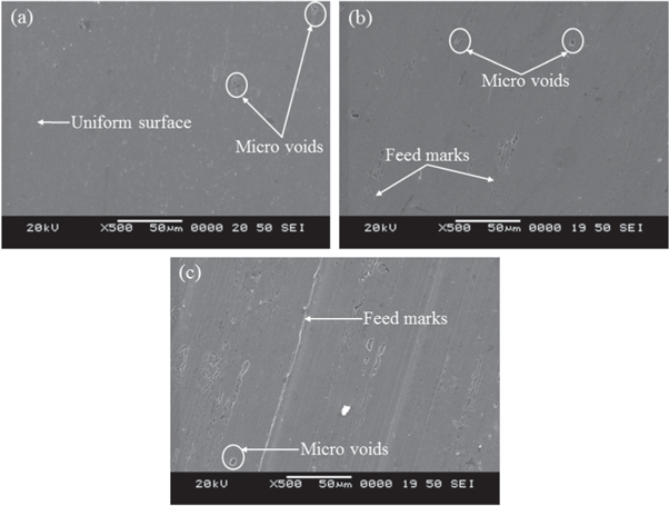
Figure 4. Diamond burnished surface obtained for a diamond sphere radius of (a) 4 mm (b) 3 mm (c) 5 mm.
Download figure:
Standard image High-resolution image3.1.3. Burnishing force
The burnishing force is considered to be one among the essential process parameter of diamond burnishing. Figure 3(c) represents the obtained surface roughness for varying burnishing force. The other two parameters namely burnishing speed of 78 m min−1 and burnishing feed of 0.065 mm rev−1 was kept constant. A similar trend has been observed for all the three diamond sphere radius best one being the radius of 4 mm. As soon as the burnishing force increases from 40 N to 115 N, the surface roughness decreases and an additional increment in the burnishing force from 115 N to 190 N causes an increase in the surface roughness. It means that minimum surface roughness was noticed for diamond sphere radius of 4 mm as depicted in figure 3(c). This can be explained by the fact that at a lower range of burnishing force, plastic deformation of the asperities will be incomplete because of the application of low burnishing force. Whereas in case of a higher range of burnishing force, the application of more burnishing force causes an improved plastic deformation of the material. This repeated plastic deformation on the surface of the workpiece leads to workhardening of the material. Flaking is also observed due to the repeated plastic deformation of the material and which could be a possible reason for the deteriorated surface finish encountered at a higher range of burnishing force [26]. The percentage improvement in the surface finish observed at a burnishing force of 115 N was 28% and 38% respectively in contrast with diamond sphere radius of 3 mm and 5 mm.
3.2. Surface morphology
The diamond burnished surface was further analyzed by using SEM images which have been taken at a constant burnishing feed of 0.065 mm rev−1, burnishing speed of 78 m min−1, and burnishing force of 115 N under MQL environment. The comparison has been made between the three diamond sphere radius of 3 mm, 4 mm and 5 mm respectively and is depicted in figure 4. From figure 4(a) it has been perceived that a uniform surface was formed and also micro voids have been observed at some spots on the surface. The feed marks were not observed in this condition. That's because the splashing of the oil mist at the burnishing zone minimizes the temperature formed on the surface which results in the easy flow of the metal to yield a uniform surface. Most of the micro voids have been filled by the easy flow of the metal over the surface after performing diamond burnishing. Figures 4(b) and (c) were observed for a diamond sphere radius of 3 mm and 5 mm respectively shows that the surface has some defects such as feed marks and micro voids. The reason for this may be due to the fact that the amount of oil mist supplied at the burnishing zone may not be sufficient to reduce the temperature and also the metal flow may not be sufficient to fill the micro voids which were present over the surface. The heat generated at the burnishing zone may not be dissipated at this condition because of the insufficient oil flow. From the previous discussion of surface roughness, it was observed that the diamond sphere radius of 4 mm has produced a good surface finish in contrast with the other two diamond sphere radius namely 3 mm and 5 mm respectively. Similar observations were made from the SEM analysis of the diamond burnished surface. It was also revealed from the surface morphology results that use of the MQL at the burnishing zone is beneficial in improving the surface quality of the surface. Diamond burnishing technique was proved to be a beneficial method in reducing the surface defects which will be generated more often in other kinds of the machining process.
3.3. Surface topography
The surface topography analysis has become increasingly important in tribology, machine condition monitoring, and materials. The surface topography analysis reveals the surface irregularities present over the diamond burnished surface. The surface topography of the burnished surface substantially affect the properties of the material. Figure 5 shows the surface topography analysis carried out for three different diamond sphere radius at a constant burnishing feed of 0.065 mm rev−1, burnishing speed of 78 m min−1, and burnishing force of 115 N. Variation in the surface has been observed as shown in figures 5(a)–(c) respectively.

Figure 5. Surface topography obtained at diamond sphere radius of (a) 4 mm (b) 3 mm (c) 5 mm.
Download figure:
Standard image High-resolution imageLowest surface intensity was observed for a diamond sphere radius of 4 mm in comparison with 3 mm and 5 mm respectively. It means that slightly a rough surface has been produced by a diamond sphere radius of 3 mm and 5 mm respectively. The reason for this variation in the surface intensity could be explained by the fact that splashing of oil mist at the burnishing zone yields less distortion. Another reason could be attributable to the low area of surface contact among the tool-workpiece available at 3 mm diamond sphere radius and similarly, a high area of contact at 5 mm diamond sphere radius. Hence, the area of contact between the diamond sphere radius and the workpiece play a vital role in producing a fine textured surface. However, a uniform surface was generated by using a 4 mm diamond sphere radius in contrast with 3 mm and 5 mm respectively. Similar observations were made in the analysis of surface roughness and surface morphology of the burnished surface. In addition, the surface topography results of the present study reveal that a diamond sphere radius of 4 mm is a better choice in order to achieve a fine textured surface which in turn lead to a fine surface quality of the burnished components. Overall from the surface topography investigation, it was revealed that the diamond sphere radius of 4 mm is suitable for diamond burnishing of 17-4 PH stainless steel under the MQL environment.
3.4. Number of passes
With the intention of understanding the influence of an additional process parameter namely number of tool passes on diamond burnishing under MQL environment, two working patterns have been considered. The two working patterns are as follows and are as shown in figure 6.
- (1)One-way working pattern
- (2)Two-way working pattern
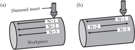
Figure 6. Functioning patterns (a) One-way, (b) Two-way.
Download figure:
Standard image High-resolution imageAll the set of experiments were conducted for two working patterns under the optimal diamond burnishing conditions such as burnishing feed of 0.065 mm rev−1, diamond sphere radius of 4 mm, burnishing speed of 78 m min−1, and burnishing force of 115 N. The surface roughness observed for one-way pattern shows that the surface roughness at lower number of passes remains constant and as the number of pass increases the surface roughness increases which is as shown in figure 7.

Figure 7. Surface roughness at varying number of passes.
Download figure:
Standard image High-resolution imageIn the two-way working pattern, the surface roughness was similar to the one-way pattern. An increase in the number of passes from 1 to 3 causes an increase in the surface roughness. The surface roughness increases if the number of passes increases beyond a certain limit because of the fact that when the tool slides over the same area of the workpiece the repetitive movement of the tool causes flaking of the surface. The repetitive movement can also cause more plastic deformation on the surface of the material [27]. Hence the surface roughness observed at the less number of passes is low in contrast with a higher number of passes. The higher range of the number of passes is not recommended in diamond burnishing process because even with the less number of passes the diamond burnishing process is capable of yielding an improved surface finish in contrast with a more number of passes. The experimental investigation also revealed that irrespective of the working patterns used in the present study, an improved surface finish is possible to obtain at a low number of passes. However, it is recommended to use a one-way working pattern instead of the two-way working pattern while performing diamond burnishing under MQL environment.
3.5. Surface hardness
In diamond burnishing process, surface hardness is also considered to be one of the important response. That's because the surface hardness can be enhanced after performing diamond burnishing process. The effect of input parameters on surface hardness are discussed as follows:
3.5.1. Burnishing speed
The surface hardness was measured at varying burnishing speed by keeping burnishing feed of 0.065 mm rev−1 and burnishing force of 115 N as constant as presented in figure 8(a). The surface hardness of the material was considered for varying diamond sphere radius of 3 mm, 4 mm and 5 mm. The variation of surface hardness shown a decreasing trend if the burnishing speed increases from 23 m min−1 to 121 m min−1. At a higher range of burnishing speed, heat generated at the burnishing zone increases. The repeated plastic deformation increases the temperature during the diamond burnishing process. At this condition, work hardening of the material takes place. The continuous increment in the burnishing speed leads to the recovery of the workhardened surface [27]. Hence decreased surface hardness was achieved with an increase in the burnishing speed. Diamond sphere radius of 3 mm has produced highest hardness in this case. The maximum surface hardness was observed to be 390 HV.
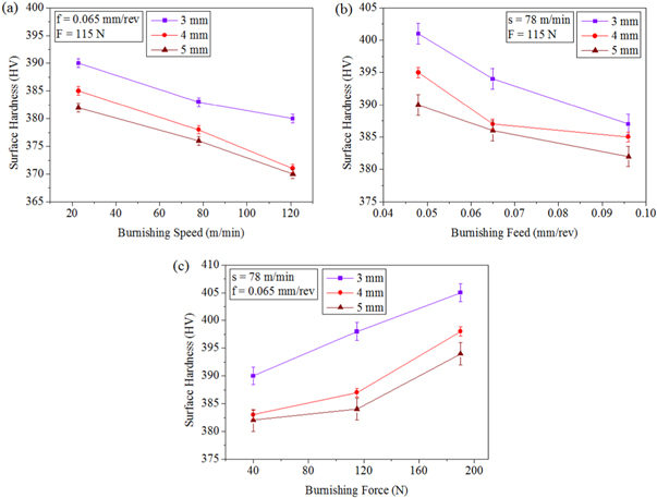
Figure 8. Surface hardness at varying (a) burnishing speed (b) burnishing feed and (c) burnishing force.
Download figure:
Standard image High-resolution image3.5.2. Burnishing feed
Figure 8(b) depicts the surface hardness obtained at varying burnishing feed and constant burnishing speed of 78 m min−1, burnishing force of 115 N. The surface hardness was observed to be decreasing continuously as there is an increase in the burnishing feed from 0.048 mm rev−1 to 0.096 mm rev−1. The trend was similar to the variation of surface hardness which was observed at varying burnishing speed in the previous discussion. It shows that the lower value of burnishing feed is a better choice to obtain maximum surface hardness. An increase in the burnishing feed leads to an increase in the consecutive traces of the diamond tip on the surface of the workpiece. The intensity of the plastic deformation decreases due to the increase in the gap between the consecutive traces of the diamond tip on the surface of the workpiece [25]. Therefore as the burnishing feed increases, the surface hardness follows a decreasing trend. A maximum surface hardness was noticed for a diamond sphere radius of 3 mm and which was found to be 401 HV. The maximum surface hardness for 4 mm and 5 mm were observed to be 395 HV and 390 HV respectively under MQL environment. Hence a higher range of burnishing feed is not recommended for obtaining superior surface hardness of the material.
3.5.3. Burnishing force
For obtaining enhanced surface hardness of the material after performing diamond burnishing process, burnishing force is considered to be an important process parameter. As illustrated in figure 8(c), the surface hardness was measured by considering varying burnishing force and a constant burnishing speed of 78 m min−1 and burnishing feed of 0.065 mm rev−1. It is obvious that a continuously increasing trend of surface hardness was noticed. The burnishing force was varied from 40 N to 190 N. At a lower range of burnishing force, the influence of plastic deformation on the material will be less. As the burnishing force increases from a lower range to a higher range, the repeated plastic deformation of the material takes place because of the application of higher pressure by the diamond burnishing tool on the surface of the workpiece. This is the reason for the workhardened surface. An additional reason for an increase in the surface hardness at a higher range of burnishing force could be attributed to the inducement of compressive residual stresses because of the application of more pressure on the material [28]. Hence the surface hardness of the material increases as the burnishing force increases. Out of all the burnishing process parameters maximum surface hardness of 405 HV was observed for burnishing force parameter and it was attained for a diamond sphere radius of 3 mm.
3.5.4. Number of passes
Some of the additional experiments were conducted to recognize the effect of an additional diamond burnishing process parameter such as the number of passes. As discussed in the previous section regarding measurement of surface roughness for the number of passes, similar methodology has been followed by considering two working patterns to identify the impact of the number of passes on the surface hardness. The number of passes has been varied by keeping all other process parameters at the optimal conditions which is as illustrated in figure 9.

Figure 9. Effect of number of passes on surface hardness.
Download figure:
Standard image High-resolution imageThe surface hardness was found to be increasing along with the increase in the number of passes. It can be observed that to attain at a maximum surface hardness of the material 3 number of pass is a better choice. In both the working patterns, a similar trend has been observed for surface hardness. As the number of passes increases, the repeated movement of the diamond tip on the workpiece surface increases which in turn lead to strain hardening effect on the surface of the workpiece [7]. However maximum surface hardness was observed for the one-way working pattern in contrast with the two-way working pattern. Three number of passes yields the maximum surface hardness for both the working patterns which has been considered in the present study and it was found to be 374 HV and 372 HV respectively for one-way and two-way working patterns.
3.6. Influence of diamond sphere radius
From the previous discussion of surface hardness and surface roughness, it was perceived that the diamond sphere radius is also one of the most affecting process parameters of diamond burnishing under MQL environment. Large surface area of the workpiece will be covered while using larger diamond sphere radius and this could cause the smaller depth of penetration at a suitable applied burnishing force. This results in higher heat generation at the burnishing zone [2, 18]. Our previous discussion on surface roughness shows that poor surface finish has been attained while using diamond sphere radius of 3 mm and 5 mm respectively and improved surface finish was obtained in case of diamond sphere radius of 4 mm. It is in consequence of the fact that the surface penetration of the tool tip may not be sufficient to clear out the irregularities present over the surface in case of diamond sphere radius of 3 mm and 5 mm. Hence deteriorated surface was observed in contrast with diamond sphere radius of 4 mm. In our findings regarding surface hardness, it was perceived that the diamond sphere radius of 3 mm had produced exceptional surface hardness in comparison with diamond sphere radius of 4 mm and 5 mm respectively. The reason for this may be attributable to the deeper penetration of the diamond tip on the workpiece surface was more in assessment with other two diamond sphere radius. The investigational outcomes show that an improved surface finish and surface hardness was obtained for a sphere radius of 4 mm and 3 mm respectively under the MQL environment.
3.7. Subsurface microhardness
While performing burnishing under MQL environment, the proper selection of the burnishing parameters plays a vital role in inducing an improved surface and subsurface hardness of the material. The obtained subsurface microhardness of the sample is as shown in figure 10. The variation was obtained for three different sphere radius and a constant burnishing feed of 0.065 mm rev−1, burnishing speed of 78 m min−1, and burnishing force of 115 N. Before measuring the subsurface hardness of the sample, bulk microhardness of as received material was measured and it was noticed to be 340 HV. The subsurface microhardness was measured just beneath the diamond burnished surface. It was found that maximum subsurface microhardness was recorded just beneath the surface and as the depth from the surface increases the subsurface microhardness was reduced and lastly, its value reaches the bulk material microhardness of the material. Out of three diamond sphere radius, maximum subsurface microhardness was observed for 3 mm followed by 4 mm and 5 mm respectively. That's because low strain rate was observed because of the less shearing occurring at the tool-workpiece interface [30]. A similar trend of subsurface microhardness has been observed from the literature [12]. Percentage improvement in terms of subsurface microhardness in comparison with diamond sphere radius of 3 mm was found to be 3% and 4% respectively in contrast with 4 mm and 5 mm.

Figure 10. Subsurface microhardness of the specimen.
Download figure:
Standard image High-resolution imageDue to the burnishing process, the material will be subjected to thermal, mechanical and chemical energy which results in strain hardening and recrystallization of the material. These effects are the major reason for causing the microstructural changes in the material [31]. The microhardness variation observed in the present study is due to the fact that the heat and the strain effects are neutralized for the bulk of the material. This is the evidence for the formation of a compressive layer and a workhardened surface after performing burnishing [32]. Another reason may be due to the formation of the hard sub-surface region beneath the burnished surface. The effect of activation energy to produce cyclic heating/cooling for internal work hardening is gradually dissipated. Therefore, as the depth increases beneath the burnished surface, the value of microhardness gradually decreases to the bulk material hardness [33]. Due to the continuous use of MQL, the temperature formed will be reduced which results in strain hardening of the surface and subsurface of the burnished material [29]. When the burnishing process was performed under the MQL environment, the grains at the top surface will be subjected to plastic deformation which in turn leads to fine grain structure which is another reason for obtaining highest hardness beneath the surface [34]. The microstructural changes are also one of the major reason for the increased microhardness of the burnished surface and beneath the surface up to a particular depth [13]. High microhardness value often indicates fine grain size and large compressive residual stresses [35].
3.8. Residual stress
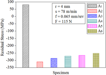
Residual stress analysis is very important because the fatigue life of the component depends on its inducement. The functional performance of a component can be substantially determined by the physical state of the surface and the distribution of residual stress near the burnished surface is treated to be one of the significant parameters. Figure 11 illustrates the residual stress distribution after performing diamond burnishing under MQL environment. The residual stress measurement was performed at a constant burnishing speed of 78 m min−1, diamond sphere radius of 4 mm, burnishing feed of 0.065 mm rev−1 and burnishing force of 115 N. The residual stresses were measured for various samples and are as follows: A1 - turning; A2 - 1-way pattern and number of pass (NOP) = 1; A3 - 1-way pattern and NOP = 2; A4 - 2-way pattern and NOP = 2; A5 - 2-way pattern and NOP = 3; A6 - 1-way pattern and NOP = 3. Initially, a basic sample (A1) was subjected to a turning process under MQL environment. It was seen that the turning process yield tensile residual stress. From the previous literature [36–39] it was known that compressive residual stresses would be induced after diamond burnishing. A similar observation was made in this study for all different samples. Out of all samples, A2 has produced a maximum compressive residual stress of 310 MPa. For all other samples, a decreasing trend of compressive residual stress has been observed. The reason for this may be due to the cyclic loading from the diamond burnished surface yields deforming anisotropy [40] and also the relaxation of the residual stress will be initiated at this point. Hence due to the relaxation, the residual stress was observed to be decreasing in all other samples as shown in figure 11.
Figure 11. Residual stress of the diamond burnished sample.
Download figure:
Standard image High-resolution image
The basic mechanism which induces compressive residual stress is mechanical deformation of the material. It will be induced due to the mechanical and thermal effect. The desired residual stress can be obtained by reducing the thermal effect. To achieve this, a lubrication technique is necessary which can substantially reduce the temperature developed during the burnishing process. Diamond burnishing under MQL environment is capable of inducing compressive residual stress by reducing the temperature developed at the burnishing zone [33, 39]. The inducement of compressive residual stress on the surface was observed to be due to the mechanical stress inducement and mechanical plastic stretching [41, 42].
3.9. Significance of MQL
Negative effects of the lubricants during burnishing can cause health complications to the operator because of the formation of mist at high pressure and temperature. Dermatological problems are quite common when an operator physically touches the lubricant. The smokes, odour, and fumes can cause skin problems. Moreover, the use of conventional fluids in the machining zone has been proved to be environmentally unfriendly and uneconomic. In order to avoid these consequences MQL system has been used in burnishing to reduce the problems faced by the manufacturing industries. Manufacturing sustainability is presumably achieved when MQL agents are used. In burnishing, MQL would likewise be a means to mitigate the negative effects of heat generated during the process. The importance of using MQL in manufacturing industries are reduced tool wear, prolonged tool life, reduced temperature, increased lubrication, better surface finish and in total an improved machinability.
The damage to the tool tip has been minimized due to the constant splashing of the MQL and also the friction between the tool-workpiece has been minimized. From the economic perspective, the usage of vegetable oil is treated to be highly economical in contrast with the other lubricants. From the environmental perspective, the MQL is a better choice because of the very less amount of lubricant will be used for the burnishing condition.
From the previous discussion about the surface integrity characteristics, it was known that an improvement in the output responses had been achieved with the help of MQL environment. The constant splashing of the oil mist at the burnishing zone has reduced the temperature which leads to the reduction in the wear rate. The rate of heat dissipation was uniform at the burnishing zone which yields improved results of the responses. As illustrated in figure 4 the feed marks formation has been reduced due to the continuous spraying of the MQL. Low coefficient of friction will lead to reduced vibration at the tool-workpiece interface which also may be another reason for the reduced feed marks on the burnished surface. By the use of MQL lubrication, the mechanical and chemical degradation of the material may be prevented.
The MQL spray and droplets can cause a tribological improvement along with the effective reduction of heat generated. The droplets are very effective in penetrating the burnishing zone and it vaporizes by absorbing the latent heat developed. The friction generated at the interface of tool-workpiece can be reduced by the impingement of MQL [43, 44]. The latent heat from the burnishing zone will be extracted when the droplet of oil impinges on the heated zone. In MQL the convective heat transfer is small in contrast with evaporative heat transfer. Hence substantial amount of heat will be removed. All the droplets of oil will be evaporated during burnishing which avoids the waste disposal problems. From the previous research works, it was revealed that MQL is a better mode of lubrication for enhancing the tool life and surface finish of the product. Hence from the present study, it was pragmatic that for diamond burnishing, MQL is a better alternative for convention flood lubrication in order to enhance the surface integrity characteristic.
4. Conclusions
This investigation presented the impact of control factors on the surface integrity features of diamond burnishing process on 17-4 PH stainless steel under MQL environment through a novel modified tool. The conclusions were drawn as follows:
- Minimum surface roughness noticed at the optimal diamond burnishing process parameter was 0.05 μm for a diamond sphere radius of 4 mm.
- Similarly, for a diamond sphere radius of 3 mm, a maximum surface hardness was achieved to be 405 HV.
- Subsurface microhardness improvement in a diamond sphere radius of 3 mm was found to be 3% and 4% respectively in contrast with 4 mm and 5 mm.
- Maximum compressive residual stress obtained was 310 MPa for sample A2.
- The proposed novel modified tool shows an improvement in the surface characteristics of the material which can lead to the improved functional performance of the component.