

Abstract
This study concerns hybrid Monte Carlo and molecular dynamics (MD/MC) methods involving a recipe for creating nickel carbide that can be applied to the graphene growth process. The time-stamped force-bias Monte Carlo (tfMC) method was used for taking care of the bond switching (BS) rate due to the concentration of carbon atoms in the nickel catalyst. It was found that the hybrid MD/MC method promotes the nickel carbide system to vibrational bond switching. This study also revealed that carbon atoms in metal catalyst are not spread randomly but rather prefer to gather in groups. This phenomenon is not caused by the BS rate only, but also by cohesive–adhesive competition between carbon and nickel atoms.
Export citation and abstract BibTeX RIS
1. Introduction
The unique properties of carbon formation series such as carbon nanotubes (CNT) and graphene make these materials of great potential use in numerous applications in many fields, including electronics, medical science and material sciences. For example, CNT can be used for hydrogen storage [1] and graphene for enhancing photovoltaic efficiency [2]. According to works from many countries, the need for renewable energy will allow graphene to become a much-used material. This is due to graphene's 2D structure causing unbounded one-electron valence of each atom carbon which promotes high carrier mobility [3].
Based on many experiments with CNT or graphene growth, chemical vapour deposition (CVD) and plasma enhanced chemical vapour deposition (PECVD) are regarded as promising fabrication methods [4–6]. These methods use metal as a catalyst (such as iron, nickel, copper or alloys), however, CVD needs a high temperature to decompose the gas carbon sources (such as methane and ethane) while PECVD only needs a low temperature in graphene fabrication.
The difference between both techniques is that in PECVD, the catalyst is in the solid phase, while in CVD graphene growth can be regarded as in the vapour–liquid–solid (VLS) phase [7]. In CNT growth, the VLS phase covers all metal catalyst clusters, but in graphene growth the VLS phase is promoted to the metal catalyst's subsurface. For special cases with nickel as a catalyst, many researchers have been conducted simulating CNT and graphene growth, ranging from using molecular dynamics (MD) only to using hybrid MD with Monte Carlo (MD/MC) [8, 9]. All of these simulations have been done with a short growth time. In fact, based on experiments, growing CNT or graphene takes around 10 min. Commonly, this situation is anticipated by giving a high C flux in the simulation [10–12]. Meanwhile, in research on the bond-switching (BS) rate, giving a high C flux will trigger the BS rate to become higher than is possible in an experimental setting [13].
To solve this problem, CNT or grapene growth simulations can be approached in two ways. The first is to deposit carbon onto metal catalyst [14, 15] and the second is carbon diffusion from inside the metal catalyst to the surface. In the second approach, it has to be assumed that carbon atoms have been dissolved onto the metal catalyst (or subsurface) and are ready to precipitate on the metal's surface. With this assumption, graphene nucleation can be solved in two ways as well. In the first method, the metal catalyst is annealed and then heated to the desired temperature. The metal catalyst then equilibrates. After it reaches equilibrium condition, one by one the carbon atoms are inserted into the metal catalyst at a specific rate [16]. The second method is similar to the first one, but the carbon atoms are inserted by randomly replacing metal atoms with carbon atoms one by one at a specific rate [17, 18]. Even if both these approaches result in amorphous phase of metal carbide and can describe CNT or graphene growth, some problems still remain with these methods. Inserting carbon atoms randomly can trigger unphysical meaning caused by interatomic potential and atoms jumping from one local minimum to another local minimum due to the 'liquid' phase of metal carbide. There should be a pre-treatment to minimize these effects before the growth process is considered.
This paper focuses on graphene growth. To solve the remaining problems mentioned above, we address a recipe for nickel carbide preparation involving time-stamped force-bias Monte Carlo (tfMC) to produce a hybrid MD/MC that was then used for simulation of graphene nucleation.
2. Computational method
In this simulation, we prepared three types of nickel carbide: Ni135C45, Ni120C60, Ni90C90. The aim of these nickel carbide types is to mimic the Ni3C, Ni2C, and NiC chemical formulas respectively, based on stoichiometry. All nickel carbide types had a surface area of 17.62 Å × 15.858 Å to mimic the subsurface region of nickel catalyst. The nickel atoms were arranged in an FCC structure and had 3.524 Å as lattice constant. All carbon atoms were initially placed in octahedral sites. The embedded atom method (EAM) potential was used to describe Ni–Ni interaction [19]. We then used the Tersoff potential to describe C–C interaction [20], while for Ni–C we used the Morse potential type [21]. This potential was re-parameterized based on density functional theory (DFT) comparison. In fact, there is a Brenner potential type for describing Ni–C interaction, but in this paper we focus on the principle of using a hybrid MC/MD to prepare Ni–C formation. All atoms were simulated inside the periodic box in all directions. Starting from this initial configuration, we equilibrated nickel carbide at 300 K. We did this to make sure the atoms in the nickel carbide resided in equilibrium condition. This is due to nickel's structure decreasing its crystallinity in the presence of carbon atoms [22, 23].
For maintaining equilibrium we used the NVT condition with a Nose–Hoover thermostat to control the temperature. After the system reached equilibrium, the nickel carbide was heated to 5300 K at a rate of 8 × 10¹³ K s−1 with rescale velocity. The reason for choosing 5300 K was to make sure there was a good mixture between the nickel and carbon atoms. Then the system was kept at this temperature with the Nose–Hoover thermostat as well until it reached equilibrium. After this, the nickel carbide was cooled down to 1000 K at a rate of 2 × 10¹³ K s−1 with rescale velocity. The system was then kept at 1000 K with the Nose–Hoover thermostat until it reached equilibrium. We chose 1000 K because in experiments using the CVD method for growing graphene, the temperature was in this range. After reaching this equilibrium, our molecular investigation was divided into two parts. First we used MD only, in which all carbon atoms evolve in the NVE condition, and then we used the hybrid MD/MC. In applying the MD method we used a 0.5 fs time step with Verlet integration. For tfMC we chose step size Δ at 0.1 Å. We then let the system go for 106 iterations for both MD and hybrid MD/MC. After the final iteration we minimized the system with the steepest possible descent. This ensures that the system is in energy minimum and not in a transition state.
3. Result and discussion
The difficulty of applying a long time scale to the graphene growth simulation was anticipated by mixing nickel and carbon atoms at 5300 K and cooling down to 1000 K. In this way we promoted the nickel atoms to their natural FCC structure, while the amorphous structure was naturally promoted when the nickel atoms bonded with the carbon atoms, this treatment can be prooved by radial distribution function (RDF) in figure 1(a). In figure 1(b), we provide a bond angle analysis to confirm the presence of crystal populations [24]. This figure shows that by mixing nickel and carbon atoms at 5300 K and cooling down to a target temperature of 1000 K, the crystallinity of the nickel was decreased when the carbon concentration increased, which agrees with experimental facts. We also can see that at least around 60% of the population of the FCC structure still existed in the case of Ni3C. We then compared the FCC structure population for all nickel carbide types with the following comparison estimation:

where FCC31, FCC21 and FCC11 are the FCC populations in nickel carbide Ni3C, Ni2C and NiC respectively. The decrease of the FCC structure population when the number of carbon atoms increased with respect to the comparison above is not surprising actually, because the BS rate as the main characteristic takes on the role of nickel carbide. However, what we can show here is that our method follows the main characteristics of nickel carbide. This means that this method is suitable for preparing nickel carbide for graphene growth, which was the main purpose of this study.
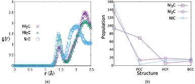
Figure 1. (a) RDF plot of Ni3C, Ni2C, and NiC. (b) Crystal population of Ni3C, Ni2C, and NiC for different structure.
Download figure:
Standard image High-resolution imageWe believe graphene growth is not only about the BS process, but there is also another key factor that is responsible for graphene nucleation. We plotted the energy distribution with respect to the coordination number (figure 2). Figure 2 shows that the carbon atoms prefer to gather in groups rather than spread individually inside the metal carbide. The reason for this phenomenon is that the cohesion between the carbon atoms is stronger than the adhesion between the carbon and nickel atoms. Therefore, if the concentration of carbon in the nickel carbide decreases, the adhesion interaction becomes weaker. This is why Ni–C interaction is stronger for NiC than for the other types of nickel carbide. This phenomenon has not been reported previously. Figure 2 also provides early predictions that Ni3C will produce graphene nucleation with ring numbers that are smaller than the other types of nickel carbide as described by reference [18]. This happens because the gregarious behaviour of the carbon atoms leads to an energy barrier region around 0.5 eV, so that this situation requires trigger energy for the carbon to diffuse in the nickel carbide.
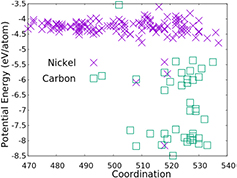
Figure 2. Potential energy distribution of nickel and carbon in Ni3C.
Download figure:
Standard image High-resolution imageBack to figure 1(a), we immediately get a more realistic bond length of Ni–C for NiC rather than the other types of nickel carbide. It has been reported that the bond length of Ni–C is around 2 Å [25, 26]. Despite the fact that we already know that the bond length of the Ni–C changes with the concentration of carbon atoms, a bond length nearing 2.5 Å is quite unwarranted. This prompted the next step in the preparation of the nickel carbide. In this case, we solved the problem in two ways: let the carbon atoms evolve in the NVE condition and evolve with MC, all in 106 iterations. The aim of this treatment is to initiate a healing process so that the bond length of the Ni–C becomes more reasonable when implementing the MC methods in the simulation, especially tfMC in this paper, due to the nature of tfMC itself.
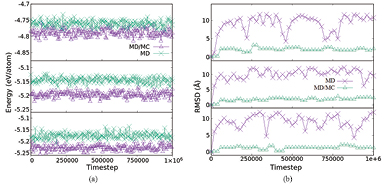
The goal of tfMC is to conduct a quantitative representation simulation over a long time scale [27]. Therefore it is better to implement tfMC in nickel carbide production to take care of the BS rate. Figure 3 shows that with only using MD, the total energy of the system tends to be stable but based on the root mean square deviation (RMSD), the movement of the atoms fluctuates more, even after 106 iterations, due to the BS rate. This means it is necessary to minimize the system to make sure the nickel carbide is not in a transition state. Because of the concentration of carbon atom, completing nickel carbide only with minimization is not enough. By implementing tfMC, however, we can take care of this long time simulation before it is terminated by the minimization method. The RMSD of the system seems to fluctuate less than when using only MD. From this we can conclude that the MD method only promotes to diffusional bond switching, whereas hybrid MD/MC promotes to vibrational bond switching. This means that hybrid MD/MC provides a faster healing process than MD. The result in figure 3 also shows that the total energy fluctuation between MD and hybrid MD/MC almost fully overlaps for Ni3C but there is a gap for Ni2C and NiC. This means that it is fine to use only MD for nickel carbide if the population of carbon atoms is less than 25%. Otherwise, we should consider hybrid MD/MC so that the healing process is faster.
Figure 3. Figure series from top to bottom are description for Ni3C, Ni2C, and NiC respectively. (a) Comparison total energy evolution of nickel carbide types. (b) Comparison RMSD evolution.
Download figure:
Standard image High-resolution image
In tfMC success, an arbitrarily small rejection rate can be obtained by decreasing the maximum allowed displacement. At specific temperatures, a 'conservative' step size is in the order of 5–10% of the equilibrium bond length. Then choosing a step size of 0.1 Å is logical for nickel carbide preparation. Even though tfMC cannot provide a representative qualitative simulation over long time scales, alternating MD with hybrid MD/MC pointed to bringing the system back to thermal equilibrium and reduce unphysical meaning produced by the tfMC algorithm [28]. For this reason, applying the tfMC method to nickel carbide promotes a better structure after the minimization process. Table 1 is total energy and bond length of Ni–C after minimization. From this table we can see that hybrid MD/MC gave almost the same total energy as MD but was more accurate for the healing process.
Table 1. Energy and bond length of All nickel carbide types after minimization.
| Method | Energy (eV/atom) | Distance (Å) | ||||
|---|---|---|---|---|---|---|
| Ni3C | Ni2C | NiC | Ni3C | Ni2C | NiC | |
| Hybrid MD/MC | −4.918 1992 | −5.313 7659 | −5.373 2362 | 2.0655 | 2.0595 | 1.95 |
| MD | −4.934 2607 | −5.330 2872 | −5.337 3804 | 2.1065 | 1.9795 | 1.95 |
4. Conclusion
Hybrid Monte Carlo and molecular dynamics (MD/MC) simulations were conducted to describe the formation of nickel carbide structures. This simulation is very useful for the preparation of graphene nucleation. A comprehensive study of hybrid MD/MC involving the tfMC method was done to verify its applicability to nickel carbide. The simulation was started by heating nickel carbide crystalline far away from the boiling temperature of the nickel catalyst. The system was then cooled down to the desired temperature and continued with or without tfMC before minimization. It was found that hybrid MD/MC can take care of the bondswitching (BS) rate due to the concentration of carbon atoms in the metal carbide. For Ni3C, the energy of the system described by both MD and hybrid MD/MC is almost fully. However, the hybrid MD/MC resulted in a faster healing process and assisted the minimization method to give the best structure. This study also revealed that graphene nucleation from nickel carbide is not only due to the BS rate but also to cohesion-adhesion competition between carbon and nickel atoms. The simulations revealed that the carbon atoms prefer to gather in groups rather than diffuse randomly in the metal catalyst.
Acknowledgment
This research was supported by 'Riset Desentralisasi DIKTI' Research Grant in the fiscal year of 2016.