

Abstract
Uniformly dispersed nanocomposite coating of aligned metallic nanowires in a matrix of amorphous alumina is fabricated by pulsed electrodeposition of copper into the pores of porous anodic alumina. Uniform deposition is obtained by controlling the geometry of the dendritic structure at the bottom of pores through stepwise voltage reduction followed by mild etching. The tribological behaviour of this nanocomposite coating is evaluated using a ball on flat reciprocating tribometer under the dry contact conditions. The nanocomposite coating has higher wear resistance compared to corresponding porous alumina coating. Wear resistant nanocomposite coating has wide applications especially in protecting the internal surfaces of aluminium internal combustion engines.
Export citation and abstract BibTeX RIS
1. Introduction
Nanocomposite coatings, with the dispersion phase having at least one-dimension in nanometer scale, can be designed to have high hardness and desired wear resistance properties [1–3]. However, two main problems in the fabrication of such composites coating are uniform dispersion of nanometer sized phase and delamination [4–6]. In this work we show that porous anodic alumina (PAA) formed on aluminium by anodisation can be used to solve both these problems. We deposit a soft metal—copper by electrodeposition into the ordered pores of alumina coating obtained by anodisation from aluminium substrate. This, results in aligned metal nanorods and single crystal alumina nanowires [7, 8] uniformly dispersed in amorphous alumina matrix. The adherence of alumina matrix with aluminium is very good, as it is obtained from the substrate. Ability to tune the size of the copper nanorod dispersion phase provides a large flexibility in custom designing wear resistant coatings for different applications.
Wear resistant materials have contrasting requirements. They should be hard in order to resist abrasive wear as per Archard wear law [9] and at the same time should have high toughness to absorb and dissipate energy resulting from frictional rubbing [10]. Hard coatings are typically brittle and fail by fracture and delamination [11]. Propagations of cracks can be arrested by the dispersion phase in nanocomposites [12, 13]. Nanoporous alumina with single crystal nanowire formed within the pores can be a good wear resistant material [8]. However, the porous structure reduces the hardness [14] with plastic deformation occurring by compaction [13, 15]. By filling metal into the pores the resistance to compaction can be increased.
Ordered porous alumina coating can be obtained by anodisation of pure aluminium using a two-step anodisation process [16]. A dense oxide layer [17], whose thickness varies with the applied anodisation voltage, exists at the interface between porous alumina and aluminium. This barrier layer offers high electrical resistance and prevents electrochemical deposition of metal [18–22]. To overcome this the thickness of barrier layer has been reduced by either by cathodic polarisation [23–25] or stepwise reduction in anodisation voltage/current [26–31]. Cathodic polarisation involves reversing the polarity and electrochemically etching the barrier layer. In this process, the OH– ions produced at the bottom of the pores etch both the barrier layer as well as the pore walls [25]. Apart from being difficult to control, this process produces a mechanically weak interface. To generate a mechanically strong interface we use the other method stepwise voltage reduction [26–31]. In this method, the anodising voltage is reduced in steps after desired length of pores has been formed. Since the pore diameter depends on the anodising voltage, this process results in a dendrite like structure [30] at bottom of the pores. Though uniform filling of pores by electrochemical deposition has been obtained [22], we find that it is difficult to ensure uniformity in the filling. This could probably because the fine dendrite structure may not result in uniform nucleation of metal across pores. We find that a mild chemical etching followed by step-wise reduction helps in repeatable uniform filling over a large area as required for tribological coatings.
2. Experimental details
PAA/Cu nanocomposite was fabricated by filling metal into the porous alumina by electrodeposition. Mechanically polished samples pure (99.999%), and annealed Al sheet (area 10 mm × 10 mm thickness 2 mm) was electrochemically polished in a solution of 20% perchloric acid in ethanol at constant voltage of 10 V for 3 min. Average roughness value (Ra) obtained from atomic force microscopy was around 10 ± 2 nm for a scan length of 90 micron. The electropolished samples were anodised by two-step anodisation process [16], to obtain uniform porous alumina. The first step anodisation was carried out in the solution of 0.3 M oxalic acid at constant voltage of 40 V at 18 °C for 30 min. The non-uniform anodised layer formed was carefully dissolved in mixture of 6 wt% H3PO4 + 1.8 wt% H2Cr2O4 at 50 °C for 30 min to leave just enough nuclei for second anodisation. The second anodisation was carried out under the same condition as first anodisation results in uniform and straight pores. The barrier layer was thinned gradually by reducing the anodising voltage from 40 to 0 V reduced linearly in steps of 1 V after every τ seconds. To optimise the barrier layer structure, different voltage reduction rates of 1 V/4 s, 1 V/8 s, 1 V/15 s, 1 V/20 s and 1 V/30 s were tried. After barrier layer thinning, the pore widening was carried out in 0.63 M oxalic acid solution at 25 °C.
The final thickness of barrier layer is measured indirectly by measuring capacitance in the anodising solution. After ensuring the capacitance of the thinned barrier layer to be above 800 nF, copper was electrodeposited into the pores. Pulse electrodeposition (PED) technique in a mixture of 0.5 M copper sulphate (Cu2SO4) and 0.57 M boric acid (H3BO3) solution was used. A negative pulse of 17 V for the duration of 3.2 ms is used to deposit copper followed by a delay of 50 ms before a positive pulse of 7 V for 3.2 ms is applied. The resulting composite coating was examined using SEM to determine the uniformity of filling. The samples were slightly mechanical polished to remove the slight overgrowth of copper from the surface.
Reciprocating contact experiment of nanocomposite coatings was conducted using ball on flat reciprocating tribometer (Ducom-TR 282-M111) under the dry condition. The hard zirconia ball reciprocated against the samples and the samples were fixed on a sample holder. The frequency and the stroke length in the reciprocating experiment are 4.5 ± 0.25 Hz and 1 mm ± 0.06 mm respectively. The forces are recorded using piezoelectric force sensor (M/s PCB Piezotronics, Inc.) and the wear depth was measured using a noncontact displacement sensor (M/s PHILTEC fiberoptic sensors). Wear experiments were conducted at a normal load of 0.1 kgf for different reciprocating cycles. All the experiments are performed at room at temperature of 25 °C and relative humidity of 48%.
3. Results and discussion
We develop a uniformly dispersed nanocomposite coating by filling copper into the porous alumina by PED. We vary the geometry of the dendritic structure to obtain uniform filling of the pores. It was found that the dendritic structure formed by reducing the voltage by 1 V every step with a 15 s gap in-between the steps results in more than 95% of pores being filled over a 10 mm × 10 mm area. From reciprocating wear tests, we find that this nano-composite coating has very little damage and wear compared to identical nanoporous alumina coating without copper nanorods.
Uniform nanoporous alumina coating is obtained by two step anodisation procedure [16]. The dense barrier layer in-between the porous alumina and the aluminium substrate by stepwise reduction in anodisation voltage. The voltage is reduced linearly in steps of 1 V after every τ seconds resulting in a linear voltage reduction. This is in contrast to the exponential drop employed by Cheng et al [30], and Araujo et al [32]. We have chosen a linear reduction as it offers fine control over the resulting dendritic structure. The rate of voltage reduction is controlled by varying τ from 4 to 30 s resulting in different dendritic geometries. A mild chemical etching after the voltage reduction is employed to remove irregularities in the dendritic structure. This results in uniform filling of the dendritic structure during electrodeposition.
We adopted a PED technique for filling Cu into the pores of the alumina coating [22, 33, 34]. A negative pulse of 17 V is applied for 3.2 ms for deposition of Cu. This was followed by a 50 ms gap. Before the start of the next cycle a positive voltage pulse of 7 V for 3.2 ms helps in reducing the uneven growth in the nanowires. This PED procedure is different from the ones that have been reported [22, 33, 34]. As our aim is to develop a composite coating of about a micron thick, we find that a positive pulse just before negative pulse results in copper growing uniformly into the pores.
The current measured during electrodeposition indicates various phases of nanowire growth in the pores. At the start of the deposition, the aluminium-barrier layer-solution interface behaves like Randles circuit [35] (figure 1(a)) with a solution resistance of about 60 ± 10 Ω. As soon as a negative voltage is applied the current reached a high value of I1, which decayed exponentially to a value of I2 with a time constant of about 0.5 ms. The magnitude of the initial current I1 decreases for about 50 pulses and then gradually increases, as the deposition progresses as shown in figure 1(b). The current (I2) at the end of the negative pulse of 3.2 ms also follows similar tread. We have found by sectioning that the dendrites get filled when I1 equals I2 which happens after about 500 pulses for our experimental conditions.

Figure 1. Variation of deposition current during pulsed electro deposition. (a) Current for individual pulses. (b) Variation of initial (I1) and final (I2) currents for the negative pulse during electrodeposition. When I1 = I2 after about 430 pulses all the dendrites are filled and sudden increase in the magnitude of I1 and I2 indicates the pyramidal overgrowth on surface.
Download figure:
Standard image High-resolution imageAfter the dendrite filling, the growth phase of nanowires proceeds with very little variation in the shape of the current pulse. This is quantified by the currents, I1 and I2 remaining more or less constant. The current during the positive pulse, even though very small, increases slightly. This is, probably, because the longer nanowires are dissolved preferentially during the positive pulse [22, 32, 36]. Once the growth into the pores is completed, the current suddenly increases as shown in figure 1(b). Further deposition results in pyramidal overgrowth of copper on the surface. To ensure uniform filling, we typically allow a slight over growth and remove the pyramids by mild mechanical polishing on a velvet cloth.
Significant differences are found in the uniformity of pore filling for different dendrite structures obtained by varying the voltage reduction rate. Figure 2 shows SEM images of the top surface of the porous alumina with different dendrites obtained by varying τ from 4 to 30 s. Copper appears as bright circles in the backdrop of grey alumina. It can be seen that almost all pores are filled when the dendrites were formed with a voltage reduction rate of 1 V for every 15 s (i.e. τ = 15 s). Percentage filling of the pores was obtained for by measuring from images taken at different locations and from at least 5 replicates (figure 2(e)). For a faster voltage reduction rate of 1/4 V s−1, the dendrite structures are shallow and have a thick barrier layer. Copper filling happens at very few individual pores. For slower reduction rates, the barrier layer becomes thinner and the uniformity improves reaching almost 100% for about 1/15 V s–1. At even slower reduction rates, the dendrite structure is very long and this prevents the uniform deposition. Thus, an optimal dendrite structure is necessary to obtain uniform filling. This optimum depends on thickness of the barrier layer as well as the total length of the dendrites. It is also observed that the mild-etching of the dendrites also affects the deposition. In all the experiments reported here, the etching time has been kept constant at 2 h in 0.63 M oxalic acid.

Figure 2. SEM images of porous alumina after copper deposition at the barrier layer structures obtained with different voltage reduction rate (1/τ) of (a) 1 V/4 s, (b) 1 V/8 s, (c) 1 V/15 s, (d) 1 V/30 s and (e) percentage of pore filling for different dendrite structures obtained by varying the voltage reduction rate.
Download figure:
Standard image High-resolution imageTo achieve repeatable near 100% filing of copper, deposition conditions were further standardised for alumina films with barrier layer formed with 1/15 V s−1 voltage reduction rates. The hardness of these coatings was measured with nanoindentation. The load-displacement curve of porous alumina (PAA) and Cu-filled porous alumina (PAA + Cu) is shown in the figure 3. The horizontal bar represents the scatter in nine measurements carried out in a 3 × 3 array. The hardness was found to be about 3.1 ± 0.15 GPa at 10 mN for a film thickness of 1 μm. This is higher compared to the similar unfilled porous alumina whose hardness was found to be about 2.2 ± 0.10 GPa. There is a pop-in behaviour in porous alumina sample at a penetration depth of about 0.2 μm. Absence of pop-in behaviour after than till the maximum penetration depth could indicate that the adhesion between film and the substrate has not been weakened in the composite coating.
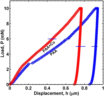
Figure 3. Load-displacement curve of porous alumina (PAA) and porous alumina/Cu (PAA + Cu) nanocomposite.
Download figure:
Standard image High-resolution imageA ball on flat reciprocating tribometer has been used to study the tribological behaviour of this nanocomposite coating under the dry conditions. The experiments were carried out with 6 mm diameter Zirconia balls as we found that the steel balls were wearing out rather than the coating. The contact load was maintained at 0.1 kgf by dead weight while the reciprocation amplitude was maintained at 1 mm with the help of a cam. Thickness of the composite coatings used in these experiments was about 6 μm. Figure 4(a) shows how the wear depth varies with the reciprocating cycles. The wear depth for pure aluminium and unfilled porous alumina are also given for comparison. The slope of these curves gives the wear rate. Initially, (for about 100 cycles) the wear rate is affected by adsorbed layers present on the surfaces and varies wildly from sample to sample. After that the wear depth increases monotonically with number of cycles. Porous alumina as well as composite coatings have a lower wear rate of 0.3 ± 0.1 nm/cycle compared to that of 4.7 nm/cycle for pure aluminium. Alumina is much harder than aluminium and hence has lower wear rate.

Figure 4. (a) Wear depth versus number of cycle of pure aluminium, porous alumina and porous alumina/copper nanocomposite, (b) wear depth versus number of cycle porous alumina/copper nanocomposite. The thickness of the porous alumina and porous alumina/Cu composite coating is ∼6 μm. SEM images of wear track of (c) porous alumina, (d) magnified image of (c), (e) porous alumina/copper nanocomposite, (f) magnified image of (e).
Download figure:
Standard image High-resolution image
The porous alumina coating fails after about 13 000 cycles of reciprocation. The failure of the coating is easily detectable by sudden change in the acoustic emission from the interface accompanied by a violent change in the wear depth measurement. From SEM images of the wear track before and after failure, it has been found that the alumina coating breaks exposing the aluminium below. The broken alumina particles act as abrasives, resulting in increased wear rate. Figures 4(c) and (d) shows the SEM images of the wear track at lower and higher magnification respectively. Agglomerated wear debris are found throughout the wear track indicating a possible formation of mechanically mixed layer.
In contrast the composite coating did not fail even after 250 000 cycles (figures 4(e) and (f)). SEM images show that the wear track is considerably narrower −420 μm for composite coating compared to 945 μm for porous alumina coating after 32 400. The presence of composite coating is also verified from the higher magnification SEM images (figure 4(f)). As the sample wears out more are of the ball comes into contact thereby reducing the contact pressure and hence the wear rate keeps on decreasing asymptotically (figure 4(b)). Apart from the scalability issues we are currently looking into extending the composite coating procedure to aluminium alloys.
4. Conclusions
In summary, we have shown that a uniformly dispersed nanocomposite coating of aligned metallic nanowires embedded in a matrix of amorphous alumina grown from a pure aluminium substrate can be formed by pulsed electrodeposition. Uniform deposition is obtained by controlling the geometry of the dendritic structure at the bottom of pores resulting stepwise voltage reduction followed by mild-etching. The composite coating has higher wear resistance compared to corresponding porous alumina samples. Aluminium alloys are widely used in industries and anodisation treatment is used to protect the material against corrosion and wear [37]. The process we have reported here has thus has wide application especially in protecting the wear surfaces including the internal surfaces of aluminium internal combustion engines. Even though we have carried out the process in pure aluminium samples, the process with slight modification can be extended to aluminium alloys.
Acknowledgments
This work was partially supported by a research grant from Space Technology Cell of ISRO.