
Abstract
Magnetorheological properties are experimentally investigated in aqueous magnetic fluid containing spherical silica nanoparticles. A bi-dispersed system is prepared using aqueous suspension of silica nanoparticles and aqueous magnetic fluid. Both these fluids exhibit Newtonian viscosity with nominal values of 1.3 and 5.8  at 20 °C. Three different samples are prepared by varying silica and magnetic fluid concentrations and keeping the total volume constant. The addition of silica nanoparticles leads to enhancement of the magnetic field induced viscosity up to the order 107
  . The magnetic field induced viscosity is analyzed using the structural viscosity model. Magnetic field induced static and dynamic yield stress values to reveal the existence of field induced clustering. An attempt is made to explain this yielding behavior using chain-like and micromechanical models. It is found that high silica fraction leads to the formation of chain-like structure. At low silica fraction, chains overlap and result into layer aggregates, which are responsible for the anomalous increase in the magnetorheological properties. This is further confirmed using magnetic field microscopic chain formations.
Export citation and abstract BibTeX RIS
Introduction
Magnetic suspensions undergo magnetic field induced transition that causes a significant change in their magnetic, rheological, optical, thermal-conducting, etc properties [1–3]. These properties are vitally important in deciding the suitable applications or application potentiality. The magnetic suspensions, a complex fluid, can be divided into two basic categories (i) magnetic fluid (MF) (ferrofluid), which is a stable suspension of single domain ferro/ferri magnetic nanoparticles, and (ii) magnetorheological (MR) fluid, which is dispersion of micron-sized magnetic particles. In MF, the size of the single domain particles remains around 10 nm, and possesses permanent magnetic dipole moment. On the other hand, external magnetic field induced magnetic dipoles and strong interparticle interactions take place in MR fluids. This results in magnetic field induced structure/aggregate formation at low magnetic field and leads to reversible transition from liquid to solid. This characteristic transition is expressed by high yield stress and increase in viscosity to several orders of magnitude [4–7]. In contrast, in the MF thermal energy is greater than the magnetic energy, which possesses small change in viscosity and zero yield stress [1, 2].
The magnetorheological properties of silica-based inverse ferrofluid have been investigated by Remo et al [8]. In this work, three different sizes, i.e. 103, 205, and 377 nm, of monodispersed silica nanoparticles were mixed in the non-aqueous based magnetic fluid. The size of the magnetic nanoparticles was ∼9 nm having 20% polydispersivity. They have reported that the magnetic field induced viscosity increases as high as 1.13  for 377 nm sized silica nanoparticles. The yield stress values were determined from the direct and indirect methods for various magnetic and silica volume fractions. The values obtained agree with the macroscopic and micromechanical models described in [9–11]. It is to be noted that the size of the silica nanoparticles is not comparable to the size of magnetic particles, thus magnetic fluid serves as a continuous medium. In this type of systems, magnetic and non-magnetic particles do not interact; hence the combined effect of both is not seen.
Islam et al [12] have reported magnetic field induced microscopic structures in the miscible suspension of aqueous magnetic fluid and latex nanoparticles. Three different sizes of spherical latex nanoparticles, i.e. 42, 108 and 220 nm with finite polydispersivity were mixed with the magnetic fluid having 20 nm sized magnetic particles. Interestingly, they have observed a 7% increase in the magnetization on addition of 42 nm sized latex nanoparticles. Herein, the magnetic field strength required to form columnar and lamellar phases is 60–70% less than compared to analogous phases in ferrofluid alone. Recently, we have reported augmentation of chain formation in the aqueous magnetic fluid by addition of halloysite nanotubes (HNT) of 50 nm sized (outer diameter) [13]. We observed that addition of HNT increases the magnetization of the magnetic fluid up to 23% compared to into the magnetic fluid alone. The rise in the magnetization in both the earlier reported systems indicates interaction between spherical nanoparticles and nanotubes.
We may hypothesize that the interaction between magnetic-non-magnetic nanoparticles could result in: (i) increase in the magnetization, (ii) transformation from chain to columnar structure, (iii) enhancement in the magnetoviscous effect, (iv) development of magneorheological properties such as static and dynamic yield stress, etc. The present paper contributes to confirming these hypotheses using magnetic fluid system prepared using magnetite (∼8 nm) and silica (∼20 nm) nanoparticles. We demonstrate the enormous increase in magnetoviscous properties, high yield stress and transformation from chain to layer structure.
Experimental
Aqueous magnetic fluid is prepared by stabilizing magnetite nanoparticles using lauric acid [14]. The x-ray analysis of uncoated particles confirms single phase spinel ferrite. The parameters determined are: crystal structure: FCC, space-group: Fd3m, lattice parameter (a): 0.8376 ± 0.0003 nm, and crystallite size: 8.9 ± 0.2 nm. The magnetic volume fraction  and the saturation magnetization of the fluid are 0.0713 and 4.77 kA m−1 (60 G), respectively. The colloidal silica (TM-40) (Sigma-Aldrich) consists of 20 nanometer sized spheres stabilized by sodium ions. The volume fraction of silica nanoparticles
  is 0.182. Three samples of magnetite–silica composite magnetic fluids FT28, FT55, and FT82 are prepared by mixing magnetic fluid and the colloidal silica dispersion (v/v). The description of the code is as follows: FT28 is prepared by mixing 20% magnetic fluids (MF) and 80% colloidal silica (TM-40), FT55 consist of 50% MF and 50% TM-40, and FT82 contains 80% MF and 20% TM-40. The magnetic fluids samples for 20%, 50% and 80% concentrations are also prepared and coded as F20, F50 and F80. The total volume in all the samples is kept constant. All the samples are stabilized at least for 24 h before proceeding for the measurements.
The steady shear magnetorheological behaviour is investigated using a MCR 301 magnetometer (Anton Paar, GmBH). Plate–plate geometry is used for the present study, which has inner plate diameter of 20 mm and the gap within plates 0.1 mm. The magnetic field applied is perpendicular to the direction of shear. Temperature during the measurement is maintained at 20 °C. In the present work, all the data are recorded in constant shear stress mode. In this mode, the strain is measured and apparent viscosity is calculated at the rim of plates using the ratio of shear stress to shear rate. The flow curve is recorded in the 0 to 177 kA m−1 magnetic field range. The general experimental protocol followed is summarized as follows: (i) pre-shearing at a constant shear rate (5 s−1) for 30 s, (ii) the system is left to equilibrate for 60 s, (iii) desired magnetic field is applied for 120 s, and (iv) shear stress logarithmically increases from 0.05 to 50 Pa at the rate of 10 pts/decade. On completion of each measurement, magnetic field is set to zero and magnet is demagnetized using program interfacing. In each measurement a fresh sample is used. Finally, in all cases, experiments are repeated at least three times with a new sample to confirm the reproducibility.
An optical microscope (MAGNUIS MLXi) with a 40x, numerical aperture (NA) = 0.65 air objective is used to record dynamics of chain formation in the samples. Optical images are recorded using a charged couple device (CCD) attached to the microscope. The permanent magnets (0.2T) are placed parallel to the plane of microscope slide to record the structural changes.
Magnetorheological measurements
The aqueous magnetic fluid and silica suspension (TM-40) exhibits Newtonian viscosity of 1.3  and 5.8
  respectively, at 20 °C (not shown here for brevity). Viscosities of the magnetic fluid with different magnetic volume fraction vary linearly, which confirms the stability of magnetic fluid over dilution. Since parent fluids are Newtonian, first of all, it is necessary to identify the nature of all three composite magnetic fluids, i.e. FT28, FT55 and FT82, in an absence of the external magnetic field. Figures 1(a)–(c) shows the dependency of shear stress on shear rate, viscosity on shear rate and viscosity on shear stress for all three fluids in the absence of external magnetic field. On applying shearing force, pre-existing structure breaks, which is a typical characteristic of Newtonian fluid. This can be seen on the log–log plot of shear stress versus shear rate and viscosity versus shear rate, where shear stress increases linearly and viscosity decreases linearly. This typical behaviour is observed in FT28 fluid. Additionally, it is also confirmed from the absence of the low-shear plateau in figures 1(b) and (c). In the case of FT55 and FT82, the plots can be divided into two regions, i.e. low shear plateau and high shear plateau, which is evident from a difference in slopes in both these regions. In FT82 fluid, steady state at low shear rate indicates that pre-existing structure does not rupture completely; this is possible where magnetic fluid possesses columnar or columnar-like structure. On sharing, columns break into chains (if they are not rigid), then at high shear they exhibit Newtonian nature. Depending on the degree of rupture of the structure, the steady state shear stress region obtained at a low shear plateau is known as a static yield stress. In the case of FT55, viscosity observed at low shear rate/shear stress is very high. It is possible that low shear plateau might have shifted to even lower shear rate, which is out of the measurement limit in the present experimental set-up. Nevertheless, in the applied shear rate, structure of the FT55 fluid is already deformed, and hence at moderately high shear rate it becomes Newtonian fluid.
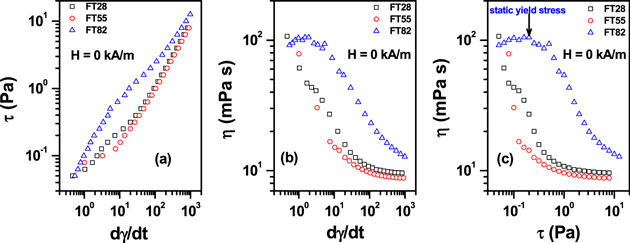
Figure 1. (a)–(c): Dependency of shear stress (τ) on shear rate  , viscosity (η) on shear rate
  and viscosity (η) on shear stress (τ) for FT28, FT55 and FT82 fluids at H = 0 kA m−1. All the plots reveal Newtonian nature of FT28. Low and high shear plateau are observed in FT55 and FT82, however each possesses different nature indicating difference in the pre-existing structure.
Download figure:
Standard image High-resolution imageIn the present magnetite–silica composite magnetic fluids, if interaction between diamagnetic SiO2 and superparamagnetic Fe3O4 exists, then it should modify the magnetorheological properties. To corroborate this hypothesis, first of all, magnetic field induced viscosity data of all the fluids are analyzed. Figure 2 shows typical flow (viscosity versus shear rate) curves of FT28, FT55 and FT82 fluids in the absence of and on application of 178 kA m−1 magnetic fields. The experimental data of intermediate field strength is not shown here for brevity; however, theoretical analyses of all the data are incorporated into table 1.

Figure 2. Flow curves of FT28, FT55 and FT82 fluids in absence and on application of 178 kA m−1 magnetic fields. Solid line is fit to power law (equation (2)).
Download figure:
Standard image High-resolution imageTable 1. Best fit parameters to the viscosity curves determined using equation (2).
| c (Pa-s2) | |||
|---|---|---|---|
| H (kA m−1) | FT28 | FT55 | FT82 |
| 0 | 0.065 | 0.038 | 0.34 |
| 16.21 | 0.125 | 0.13 | 2 |
| 29.28 | 0.07 | 0.34 | 3.2 |
| 41.90 | 0.08 | 0.45 | 5.2 |
| 54.07 | 0.08 | 0.6 | 5.5 |
| 65.80 | 0.09 | 0.65 | 6.3 |
| 93.14 | 0.08 | 0.8 | 6.8 |
| 177.04 | 0.085 | 0.95 | 8 |
| n | −0.78 | −0.67 | −0.9 |
 ( ( ) ) |
0.011 | 0.01 | 0.01 |
As discussed above, at zero magnetic field, all fluids exhibit Newtonian nature at higher shear rate, however, they behave differently at a low shear region. Such a difference is more pronounced in the presence of magnetic field. The FT28 fluid possesses Newtonian nature even in the presence of the magnetic field. The behaviour of FT55 and FT82 is to a certain extent similar in the absence and presence of magnetic field, except viscosity increases by orders of magnitude. A low shear plateau is not observed in FT55 even at a high magnetic field of 178 kA m−1. This rise in viscosities is dedicated to the magnetic field induced chain or column formation. In order to understand the effect of external magnetic fields on the viscosities of pure and silica added magnetic fluids, the change in the field induced viscosities—so- called magnetoviscous effect (MVE), i.e. R—is calculated using equation (1).

where, the  and
and  are the viscosities in the absence and presence of the magnetic field at a constant shear stress. Figure 3 shows the MVE as a function of shear stress at 178 kA m−1 field strength. The MVE data can be divided into two parts, i.e. below the peak and above the peak. The former indicates structure build-up (or shear thickening), and the latter structure break-up (or shear thinning). It is evident from figure 3 that, the magnitude of R is high in F100 compared to F50. Also, a small change in the peak position is also observed. It is known that high concentration of magnetic particles gives rise to the interparticle interaction, and thus field induced chain formations. It is also reflected in the R values. It is known that a fraction of larger particles form chains in the presence of magnetic fields, thus only these particles contribute to the magnetoviscous effect.

Figure 3. Magnetoviscous effect observed under external magnetic field strength of 178 kA m−1.
Download figure:
Standard image High-resolution imageIt is derived from the MVE values of F50 and FT55 that silica nanoparticles give rise to the magnetic interaction. The observed high R value and shift in the peak position indicates interaction between silica and magnetite nanoparticles. Since total number of magnetic particles in the fluids remains constant (in F50 and FT55), rise in R is attributed to the increase in the interparticle interaction. The magnetoviscous effect observed in the FT82 fluid is quite high compared to even pure magnetic fluid. This is only possible if strong interaction between silica and magnetite nanoparticles exists. The negligible value of R (∼0.1 to 0.3) observed in FT28 (not shown here for brevity) is attributed to the diamagnetic contribution of silica.
It is summarized based on the collective analysis of FT55 and FT82 that, (i) magnetic field induced viscosity values of silica–magnetic fluids are high compared to pure magnetic fluids, (ii) the rise in the magnetoviscous effect is owing to the presence of larger sized magnetic particles, (iii) hence, on addition of silica nanoparticles the size of the magnetic particles increases, (iv) it results in augmentation of chain and/or column formation. However, detailed analysis is required to confirm these results.
The shear rate dependency of magnetic field induced viscosity (figure 2) follows the power law [8], which is described by equation (2).

where,  is the shear rate and c, n and
  are the fitting constants. Here
  is the field independent high shear viscosity. Best fit parameters for all the samples are reported in table 1. It is to be noted that value of an exponent 'n' remains around 0.67 in FT55. This value is close to the ideal value 0.66 (i.e. 2/3), which corresponds to long-range coupling between dipolar chains [19], while, in the case of FT28 and FT82 it is deduced to be 0.78 and 0.9, respectively. Similar values are observed in the inverse ferrofluid (de Gans et al [15], n = 0.8–0.9, Volkava et al [16] n = 0.74–0.87, Remos et al [8], n = 0.65–0.73, Felt et al [17] n = 0.74–0.83, etc). The high value of 'n' suggests the formation of spherical and/or cylindrical chains, which are attributed to the interparticle interaction and explained using a micromechanical model. Here, more pronounced magnetoviscous effect is observed in FT82. This can be seen from the high values of a coefficient of shear rate 'c', which is almost one order of magnitude higher than the other two fluids. This higher value of 'c' indicates that the structurization processes depend not only on the ratio
  , but also on shear rate and the strength of applied magnetic field. Therefore, it is important to understand magnetic behaviour of composite magnetic fluids in static condition, which is governed by magnetostatic energy.
Since in the flow curve of composite magnetic fluids, magnetostatic and hydrodynamic forces are expected to dominate, an attempt is made to obtain a master curve using scaling law  (not shown here for brevity). However, they do not overlap in all cases. Therefore, the detailed analyses of flow curves are analysed based on mason number, Mn, which represents dimensionless shear rate and defined as a ratio between hydrodynamic and magnetostatic forces [18],

where,  is the viscosity of magnetic fluid, continuous phase,
  the shear rate,
  the permeability of vacuum, coupling parameter or constant factor,
  with
with  the relative permeability of the silica nanoparticles,
  the relative permeability of magnetic fluid, and H the magnetic field strength. By using the Mason number (equation (3)) and the shear viscosity definition,
  , the modified Mason number can be written as,

Based on the above relation, the values of Δ and Mn* determined for FT28, FT55 and FT82 are: Δ = −0.76, −0.80 and −0.82, and Mn* = 0.141, 0.202, and 0.257, respectively. However, we could not get a good fit at low shear regime. Recently, it has been reported that the low shear rate plateau can be fitted with the structural viscosity model [19], given by,
Where,  is the low shear viscosity, which was not considered in the equation (4). Hence equation (5) can predict the existence of a low shear viscosity plateau value with smooth transition from the low to high (Newtonian) shear plateau.
Figure 4 shows dimensionless viscosity  as a function of normalized Mason number
  fitted using structural viscosity model (equation (5)) at various magnetic field strengths. This model describes the shear viscosity from the balance between build up (magnetic field-induced clustering) and breakdown (shear induced breakup) of particle aggregates. The values of
  determined from the fit are 0.0035, 0.09 and 0.65, respectively for FT28, FT55 and FT82 fluids. This enhancement in
  (by order(s) of magnitudes) is attributed to an increment in the field induced clustering. It is evident from figure 4 that the structural viscosity model enables one to fit low shear plateau region in FT28 and FT82 fluids, however, in FT55 theory deviates at low shear region. High values of normalized viscosity predict the existence of certain degree of aggregates or strong structure in FT55. Further findings are needed to understand this phenomenon. Finally, it is envisaged from the magnetic field induced viscosity data and its analysis that the pattern of magnetic field induced structure formation in all three fluids is different. More information and understanding about these structures can be obtained from the rheograms.

Figure 4. Dimension less viscosity  as a function of normalized Mason number
  fitted using structural viscosity model (equation (4)) at various magnetic field strength.
Download figure:
Standard image High-resolution imageFigure 5(a) shows rheograms (shear stress verses shear rate plots) of three fluids at the typical magnetic field strength. Figure 5(b) shows plots of viscosity (η) verses shear stress (τ), which is important to understand the progressive structure formation on increasing magnetic field and its flow behaviour. Since measurements are carried out in the steady shear stress mode, a vast difference in the shear rate decades is evident in all the fluids. This indicates a difference in the magnetic field induced structure. In the absence of magnetic field, shear stress (τ) linearly varies with the shear rate  . However, on switching on the magnetic field, totally different behaviours are observed in all three fluids.

Figure 5. (a) Rheograms (shear stress (τ) verses shear rate  plots) and (b) plots of viscosity (η) verses shear stress (τ), for FT28, FT55 and FT82 fluids at different magnetic field strength.
Download figure:
Standard image High-resolution imageDepending on the degree of rupture of the structure, yield stress is defined by the static and dynamic yield stress. The static yield stress is obtained by extrapolating the shear stress at the intermediate pseudoplateau, i.e.,  in the log–log rheograms; it is related to the breakage of the structures at their weakest point. Usually static yield stress is a characteristic of the magnetorheological fluids. The dynamic yield stress relates to the complete breakage of the structure, and is usually estimated by fitting the high-shear rate part of the rheogram in linear-scale
  to the Bingham equation,
  , where η is the plastic viscosity. Figure 5 shows the dynamic yield stress values determined at different magnetic fields for all three fluids. It also shows the static yield stress obtained at a constant shear rate 0.5 s−1 at different magnetic fields in FT82 fluid.
In FT28, magnetic field induced shear stress superimposes suggesting a Newtonian behaviour of the fluid. This is expected behaviour in the magnetic fluid having low magnetic volume fraction. The dynamic yield stresses obtained at the different field are almost field independent and remain around 0.12–0.18 Pa. The same is also evident from figure 5(b). Hence, fluid illustrates the balancing between field induced structure formation and shear induced deformation.
In FT55, figures 5(a) and (b) signify low and high plateaus, however, low shear plateau is not very clear. In the presence of magnetic field, rheological behaviour changes to a plastic behaviour. The plastic behaviour is characterized by the appearance of a yield stress,  , which is necessary stress to induce the flow and manifested by the intermediate pseudoplateau. The observed low shear plateau probably suggests that pseudoplateau might be obtained by increasing magnetic field. The dynamic yield stress values obtained for this fluid that magnetic field induced structure formed in this fluid is stronger than FT28. The
  increases linearly around 60 kA m−1 and then it saturates. This is the yield stress value to starts the flow, meaning structural deformation process completes around 60 kA m−1.
The FT82 fluid clearly demonstrates low and high shear rate plateau that correspond to static and dynamic yield stresses. At 16 kA m−1 field, noticeable change in the data of FT82 fluids in obtained compared to FT55, suggesting enhancement in the magnetic field induced structure formations. It is noticed from figures 5(a) and (b) and 6(a) and (b) that: (i) static yield stress (σ) linearly increases up to ∼60 kA m−1 and then it saturates, (ii) dynamic yield stress, which is almost double (σ), linearly increases up to 60 kA m−1 and it goes towards saturation. The values of static yield stress confirm that the process of magnetic field induced structure formation completes around 60 kA m−1, whereas non-saturating behaviour of  indicates that structure deformation process does not complete in the given field range. The static and dynamic yield stresses are the typical characteristics of magnetorheological fluid (MRF) and also inverse magnetic fluid (inverse ferrofluid). The high value of σ is indicative of formation of layer aggregates. However, it can only be confirmed using various available models.
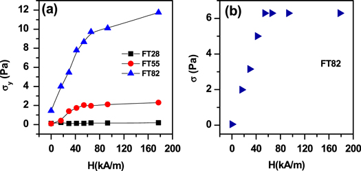
Figure 6. (a) Dynamic yield stress  determined from high shear plateau and (b) static yield stress determined from low shear plateau at various magnetic fields (H). Solid line is a guide to the eye.
Download figure:
Standard image High-resolution imageAs mentioned above, contrast factor or coupling parameter, β, depicts that magnetic interaction exists in the system. Additionally, high value of fitting constant 'n' and variation in  indicates that the field induced structures formed in all three fluids are not the same. It is possible to predict the type of structure formed in each fluid by knowing the dynamic yield stress values and the contrast factor (β). The fact that yield stress strongly depends on the interparticle/interchain interaction can be described using different models, as discussed below.
Chain like model
In this model the effect of interparticle interaction is considered. A simplified form of this model from Klingenberg and Zukoski [10] is expressed as,  . It is assumed here that non-interacting chains of particles are moving parallel to the applied magnetic field and rigidly attached to the wall. Under the assumption that the motion of the chains is not affine with the shear and chain opens between first and second particles, then normalized yield stress is given by,
  . This is known as bead-rod model. Contrary to both the above chain models, normalized yield stress is defined by considering the particle size and gap thickness, which is given by,

where, C is chain constant and it directly depends on the particle size.
Figure 7 shows chain-like model aggress in the case of FT28 and FT55 fluids, with the chain constant 'C' equal to 0.085 and 0.4, respectively. But it did not agreed with FT82 fluids.

Figure 7. Normalized yield stress verses contrast factor fitted using various models (see text).
Download figure:
Standard image High-resolution imageMicromechanical models
These models are based on the macroscopic description of structure by considering the shape anisotropy of the strained aggregates under small deformation. Internal structure within the aggregates is ignored and only the particle volume fraction is required as an input in this model. In the case of randomly closed spherical aggregates, it is assumed that  , but a small change in this value is found. A generalized yield stress model in the case of lattice of magnetic cylinders and stripes is described by Bosis et al [9] as,
where, relative permeability difference between the aggregates  and the composite magnetic fluid
  is quantified as,
  . As a first approximation, a mean field theory is used to described the magnetic permeability of the aggregates in composite magnetic fluid as,
 , where
  is the non-magnetic particle volume fraction and
  . In equation (7), C = 2 suggests cylinder-like aggregates, whereas C = 1 implies layered aggregates. Normalized yield stress determined for FT82 is fitted to equation (7) with C = 1. This confirms that high values of 'n', 'Δ' and Mn* obtained are due to formation of layered aggregates in FT82 fluid.
Hence, we summarize from the analysis of magnetorheological measurements that normalized yield stress data of FT28 and FT55 fits chain-like models, whereas FT82 fits to macroscopic bead-like model. Chain constant in FT28 is very small, indicating either weak chain formation or number of chains per unit area are less. In FT55, the chain constant is an order of magnitude higher than the FT28, meaning strong chain formation. FT82 fits to the macroscopic model, with constant C = 1, which indicates layer structure formation. This is further confirmed using microscopic measurements in the presence of external magnetic field.
Microscopic evidence of field induced structure formation
Figure 8 shows magnetic field induced chain formation in FT28, FT55 and FT82 fluids at a constant magnetic field of 16 kA m−1. It is found that length of the chain and number of chains per unit area increase as we go from figures 5(a) to (c). In FT28 chains are short and scattered, while in FT55 chains are quite long and continuous. It is noted that the values of C obtained from equation (4) are 0.085 and 0.4, respectively, for FT28 and FT55. Correlating the optical microscopy results, the values obtained from the fitting of chain-like model are in agreement. The chains observed in the FT82 are thicker compared to the other two fluids. Careful observation of the image indicates that chains are overlapping. This is in acquiescing with the layered structure arrangement obtained from the macroscopic model.

Figure 8. Microscopic confirmation of chain formation in (a) FT28, (b) FT55, and (c) FT82. Images captured at H = 16 kA m−1. Scale-bar represents 10 μm.
Download figure:
Standard image High-resolution image
Conclusion
The present paper demonstrates that the magnetorheological properties of aqueous magnetic fluids are enhanced by addition of mono-dispersed silica nanoparticles. Three samples, FT28, FT55 and FT82, of bi-dispersed magnetic fluids are prepared by varying magnetic and silica fractions. Depending on these fractions, the magnetic field induced viscosity varies from 102 to 107  . This anomalous increase in the magnetorheological properties are attributed to the formation of magnetic field induced chain-like structure and layer aggregates. This structure is further confirmed using field induced microscopic studies.
Acknowledgement
The authors acknowledge CHARUSAT and Department of Science and Technology, Government of India through project no. DST-161-G.