

Abstract
The character of hard ZrO2p in dry sliding wear of Al-Zn(-Mg) alloy was investigated in the cast and heat-treated conditions using a pin-on-disc wear tester at fixed sliding speed (3.5 m s−1) and varying applied pressure (0.5–2.125 MPa), giving special accentuation on the response parameters such as seizure resistance, wear rate, and bulk temperature rise. Hardness behavior was also studied for the same concerning materials in accordance with ASTM standards. The composites exhibited enhanced hardness, wear and seizure resistance, and greater temperature rise over the alloy. Indeed, the wear rate at preliminary stages increased with increasing applied pressure up to a transition limit beyond which it upsurged abruptly to greater value at the seizure pressure. Heat treatment also significantly improved the hardness, and resistance to wear and seizure. Amongst, heat-treated composite embedded with 4% ZrO2p yielded the highest hardness of 180 HV and seizure pressure of 2.125 MPa, respectively. The deformation in the subsurface was examined in terms of microhardness variation along the depth perpendicular to the worn surface. It was detected that the presence of ZrO2p not only enhanced the seizure resistance but also effectively hampered the extent of subsurface deformation at the seizure. The wear mechanism was prevalently governed through the establishment of the mechanically mixed layer (MML), oxide layer, cracking, and deformed subsurface.
Export citation and abstract BibTeX RIS
Abbreviations
| AMCs | (aluminium metallic composites) |
| subscript p | (particle) |
| subscript mp/np | (micro-particle/nano-particle) |
| ZrO2p | (zirconia particle) |
| wt.% | (weight percentage) |
| AC | (as-cast) |
| HT | (heat-treated) |
| h | (hour) |
| min | (minute) |
| EDX | (energy dispersive X-ray spectroscopy) |
| MML | (mechanically mixed layer) |
| FESEM | (field emission scanning electron microscope) |
| PDZ | (plastically deformed zone) |
| UDZ | (undeformed zone) |
1. Introduction
Aluminium alloys have emerged as new promising materials with potential applications in a variety of sectors such as automobiles, defense, aerospace, and other engineering fields due to their higher stiffness and specific strength, superior resistance to wear and seizure, and better-elevated temperature strength [1]. These innovative materials have acquired a lot of traction in the automotive industry in the last few years to improve fuel efficiency [2]. The effectiveness of many automotive parts is determined by their mechanical and tribological characteristics, such as hardness, wear, and frictional behavior. There has been a lot of emphasis in recent years on using high-strength Al alloys in a variety of structural and general engineering applications. However, when compared to other similar and dissimilar metallic alloys, one of the most significant drawbacks of such high-strength Al alloys is their poor weldability (integrity) [3]. As a result, these products are typically joined by bolting or riveting, making them more susceptible to oscillation/vibration in such situations, which can lead to sliding and fretting wear in a dry environment. This has necessitated a continued investigation into the sliding wear response of such high-strength Al alloy systems in a dry environment.
The strengthening effect of various types of reinforcements on the Al matrix composite differ depending on the nature of the reinforcement. Amongst, SiCmp has been recognized as a well-studied reinforcement in the Al matrix [4]. When compared to the monolithic material, a large percentage of reinforcements, up to 15% SiCmp, were used to improve the hardness, density, and tensile strength of the composite [5]. The use of Al2O3mp reinforcement in Al composites has resulted in a significant improvement in microhardness, wear resistance, and tensile strength [6]. Similarly, B4Cmp has also been significantly employed to enhance the strength of AMCs [7]. Though, in some instances, B4Cmp reinforced composite had exhibited lower wear resistance as compared to that reinforced with SiCmp [8]. Moreover, zirconia particle reinforced composite had shown remarkable improvement in the hardness and tensile strength [9]. Fly ash i.e., an industrial waste had also offered superior compressive strength of AMCs [10]. Nevertheless, reinforcing fly ash led to a reduced tensile strength of the composite material. Apart from this, nanomaterials have also been successfully adopted as reinforcement. Carbon-based nanostructures, in particular, have shown great promise in improving the properties of AMCs. Carbon-based nanomaterials commonly used for reinforcement applications include carbon nanotubes (CNTs), graphene nano-platelets (GNPs), fullerenes, nanodiamonds, and carbon fiber [11].
Furthermore, investigating sliding wear, Acilar et al [12] found increased volumetric wear in the materials with the increased either normal load or sliding run distance. Daoud et al [13] observed a reduced wear rate in the Al-Si alloy composite up to an applied load of 90 N, while on further increasing the applied load, it increased due to fracture of particle resulting in decay in load-bearing ability. Uyyuru et al [14] clearly established the robust relation between sliding speed and normal load causing material wear and reported that frictional coefficient and wear rate were significantly altered with varying sliding speed and applied load. Also, with increasing normal load, the wear rate was increased, whereas the frictional coefficient was reduced. Identification of wear mechanism offers a better idea to design and develop improved wear and seizure resistant components subjected to sliding wear conditions. While constructing wear mechanism maps for Al alloys, Liu et al [15] suggested oxidation, delamination, severely plastic deformed zone, and melt wear regimes. Bembalge et al [16] found abrasive wear mode along with adhesive wear marks at lower load and speed, however, it transformed into oxidational wear mode when undergoing higher load and speed. Wilson et al [17] noticed that the addition of 20% SiCp to A356 Al alloy significantly extended the mild wear regime to a higher extent of applied load and sliding speeds, henceforth inhibiting severe wear. Beyond a critical load, a severe wear regime was observed by Zhang et al [18], resulting in considerable surface degradation and material transfer to the counter disc. James et al [19] noticed a static mild and smooth type of wear regime in AA6061 composite containing 5% ZrO2p, and with increasing the ZrO2p concentration to 15%, some agglomerated cites were evident, which in due course resulted in deep ploughing, grooving, and delamination type of severe wear. Ramchandra et al [20] observed oxidation, micro-cutting, and thermal softening operative wear mechanisms. The evolution of the mechanically mixed layer (MML) onto the worn surface of metallic alloys robustly dictated the wear response in the materials [21, 22]. The mechanically mixed layer was characterized by Rosenberger et al [23], which comprised of the matrix material, counter surface, matrix oxides, and cracked ceramics reinforcement. Furthermore, Basavarajappa et al [24] detected increased microhardness in the vicinity of the worn end of the subsurface due to the formation of thicker MML. It was also noted that the level of subsurface deformation got reduced due to the addition of graphite reinforcement. Venkataraman et al [25] suggested a correlation of transitional load with the material hardness on the basis of varying nature of MML, cracking of subsurface and other microstructural changes. It was stated that transition load got increased with the increase in hardness of MML. The occurrence of wear residues, material displacement (transfer) from the counter disc, coalition of mating surfaces under higher normal loads, and greater heating due to friction were the foremost facets responsible for the evolution of the MML. Uthayakumar et al [26] reported that formation of debris was greatly influenced by thickness of tribo-layer and subsurface deformation, and lesser subsurface deformation led to reduced size of wear debris with equiaxed dimension.
Given the foregoing review, it is evident that research into the prevalent wear mechanisms and the extent of subsurface deformation synergistically allowing sliding wear in high strength alloy embedded with a hard particle is very scarce. To address such a significant research gap, an effort has been made to explore the dry sliding wear of stir-squeeze cast Al-Zn(-Mg) matrix alloy and its composites embedded with 2 and 4% ZrO2p at varied normal pressure under heat-treated (HT) and as-cast (AC) conditions. The effects of incorporating ZrO2p dispersoids into the matrix alloy and T6 heat treatment on hardness, seizure resistance, and wear resistance have been thoroughly investigated. The worn-out surfaces and subsurfaces generated while conducting the test were then carefully micro analyzed to visualize the operative wear mechanisms and degree of subsurface deformation.
2. Experimentation
2.1. Synthesis of materials
AA7068 containing Zn-7.8%, Mg-2.3%, Cu-2.4%, Fe-0.15%, Mn-0.1%, Ti-0.1% and Al rest has been selected as matrix material. An enhanced stir-squeeze route equipped with an ultrasonic transducing probe was adopted for the synthesis of matrix alloy and composites embedded with 2 and 4 wt.% of ZrO2p of a size range of 20–25 μm. Figure 1 merely depicts the morphology and distribution of ZrO2 particles in an as-received state. In actual practice, particles with only a size range of 20–25 μm were separated using a sieve and employed in the fabrication process. Herein, AA7068 was heated in a bottom pouring electrical resistance furnace at 750 °C and ZrO2p was preheated at 500 °C in a muffle furnace. Preheating of particles avoids moisture from the surface, enhances wettability, and prevents thermal shock due to sudden temperature drop during the mixing of reinforcing particles in the molten alloy. Coverall-11 flux powder was spread in the molten matrix for cleaning and dross removal from the melt surface. Purging (degassing) was carried out through dry N2 gas (Grade-1) to avoid uninvited reactions during the process. A mechanical stirrer rotating at a speed of 350 rpm (assisted with three stainless steel blades inclined at an angle of 45° each) was employed to form a vortex of alloy. Meanwhile, preheated ZrO2p and Mg (1 wt.% in small ingot form to enhance the wettability) were inducted into the molten alloy while stirring at 500 rpm for 8 min followed by ultrasonication to agitate the stirred composite mixture at a frequency of 25 kHz for 5 min. Ultrasonication offers better mixing and avoids clustering of reinforcing particles in the matrix alloy. The composite mixture was then transferred to the squeezer via runway preheater maintained at 250 °C where a load of 100 MPa was applied to this composite mixture using a hydraulic press. Solidification of the castings was allowed inside the predefined molds. The enhanced stir-squeeze casting route can be seen schematically in figure 2. The synthesized alloy and composites are designated as A (AA7068), C1 (AA7068%-2% ZrO2p), and C2 (AA7068%-4% ZrO2p), respectively.
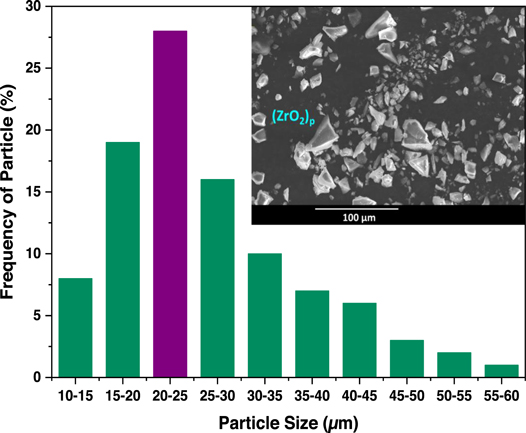
Figure 1. Morphology and distribution of ZrO2 particle in as-received state.
Download figure:
Standard image High-resolution image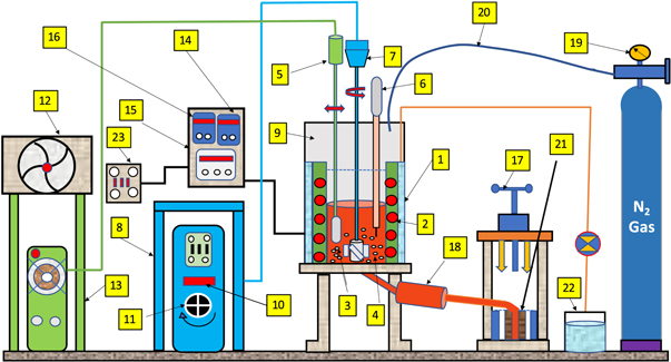
Figure 2. Enhanced stir-squeeze casting route integrated with ultrasonic agitator. Depiction for figure 2: 1. Electrical resistance furnace, 2. Heating coils, 3. Reinforcing agent, 4. Matrix phase, 5. Ultrasonic agitator, 6. Thermocouple, 7. Stirrer blade assembly, 8. Stirring control unit, 9. Vacuum chamber, 10. RPM display, 11. RPM switch, 12. Air cooling fan, 13. Ultrasonic control unit, 14. Temperature display, 15. Main control unit, 16. Current display, 17. Hydraulic press, 18. Runway preheater, 19. N2 gas flow controller, 20. Stainless steel pipe, 21. Die, 22. Coolant sump, 23. Three-phase power supply unit.
Download figure:
Standard image High-resolution image2.2. T6 heat treatment
The synthesized matrix alloy, as well as composites, were undergone T6 heat treatment (artificially aging) in an automatic programmable muffle furnace. The heat treatment cycle, schematically shown in figure 3 primarily consists of three stages i.e., (i) Solutionizing: materials are heated at 490 °C  5 °C for 8 h to dissolve the solute elements in the Al solid solution, (ii) Oil quenching: rapid cooling of solutionized materials in an oil bath to achieve supersaturated solid solution and avoid the precipitation of the solute elements, and (iii) Artificial aging: reheating of quenched materials at an optimized aging temperature of 195 °C [27] for 6 h to obtain superior hardening.
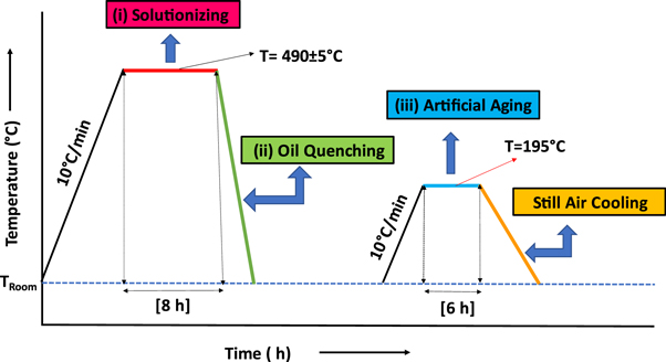
Figure 3. Heat treatment cycle consisting of solutionizing, oil quenching, and artificial aging.
Download figure:
Standard image High-resolution image2.3. Microstructural analysis
The samples (cylindrical size: 10 mm × 10 mm) were metallographically polished following the standardized method and subsequently etched using Keller's reagent. The samples were then micro analyzed through FESEM (Model: NOVA NANOSEM-450). The phases were identified using the XRD technique (model: RIGAKU-JAPAN) using Cu-K radiation at a wavelength of 1.54 Å.
2.4. Hardness measurement
The hardness test was carried out on the polished surface adopting ASTM E-18 standard using Digital Rockwell Tester (FIE make, model: RASNE-1) in a still atmosphere. The specimen was tested by applying a load of 100 N for 10 s through a 1/16'' steel ball indenter on the B scale. Tests were conducted at ten different locations to eliminate the possible indenter effect existing on hard ceramic reinforcing particles, and the average of all ten readings was reported. Notably, Rockwell hardness values (HRB) were converted into Vickers hardness (HV) to ensure consistency in the hardness measurement throughout the study.
2.5. Dry sliding wear
Wear test in the dry sliding environment was conducted using pin on disc wear apparatus (Ducom, make, Model No TR-201 CL) as per the ASTM G99-95 standard, refer to figure 4 for schematic illustration. After each run, the surface of the specimen and counter disc were cleaned by using acetone and cotton to avoid the uninvited adhesion of wear debris. An electronic microbalance (accuracy of 0.01 mg) was used to calculate the weight loss before and after each run. The sliding wear test was carried out either for a traveling distance of 5000 m or to the extent where the pin material gets seized, whichever was detected first. The incidence of the seizure during the test was described through the prevalence of unusual noise and intensive vibration, and a hasty upsurge in bulk temperature. Sticking/adhesion of material on the counter disc (material flow from the mating surface) was also noticed by the naked eye. The sliding distance and applied pressure were noticed whenever the material got seized for the measurement of wear response parameters. The description of test parameters is provided in table 1.
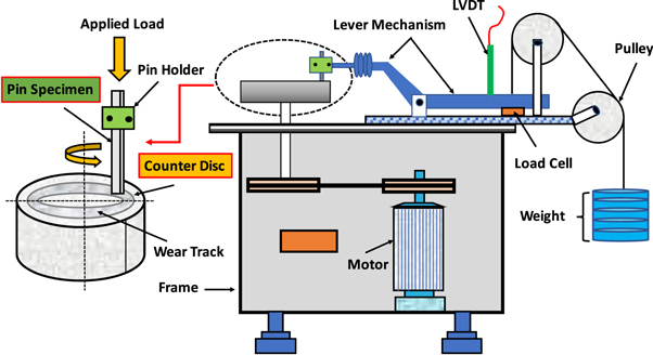
Figure 4. Pin on disc wear test apparatus.
Download figure:
Standard image High-resolution imageTable 1. Details of wear test parameters.
| Test Parameter | Description |
|---|---|
| Still environment | Temperature (27 °C–29 °C) and Humidity (60%–65%) |
| Specimen | Cylindrical pin ϕ10 × 30 (mm) |
| Counter disc | EN32 grade steel (hardness of 65 HRC) |
| Track diameter | 100 mm |
| Sliding speed | 3.5 m s−1 (fixed) |
| Applied load | 0.5–1.0–1.25–1.375–1.5–1.625–1.75–1.875–2.0–2.125 (MPa) |
| Sliding distance | 5000 m (fixed) |
The evaluation of wear rate was made through the weight (material) loss approach and expressed as volumetric loss per unit sliding distance (mm3/m). To note down the temperature value, a bare thermocouple tip (type K) was put into a narrow-drilled 2 mm diameter hole in the lateral surface of the pin sample at a 2 mm distance away from the mating zone. Therefore, the pin sample was grasped in such a manner that a part of the sample of size 4 mm was remained outside of the sample bearer. It is also noteworthy that the temperature values recorded during these tests were the temperature values of the location onto which the thermocouple was inserted and thus, actual temperatures of the mating zone could be greater than the noted values.
2.6. Worn-out surface and subsurface studies
These studies were conducted through FESEM to predict the governing wear mechanism in terms of microstructural changes and subsurface deformation. The wear-out surfaces were slashed vertically to micro analyze the subsurface behavior. Subsequently, the Vickers microhardness test was also conducted at the polished and etched subsurface along the depth by applying a 50 gf load for 10 s. Microhardness variation was computed nearly 20 μm from the worn end, and afterward at an interval of 20 μm for the successive indentations until disparity in microhardness with the bulk material hardness got almost obsoleted.
3. Results
3.1. Microstructure
Figure 5(a) depicts the microstructure of AA7068 matrix alloy where primary α-Al in a lamellar eutectic manner and compound η-MgZn2 are evident. It displays a rosette-like characteristic of α-Al grain solid solution enclosed by inter-dendritic secondary phases. The microstructural change in the alloy during heat treatment can be seen in figure 5(b). Therewith, figures 5(c) and (d) reveal the uniform distribution of ZrO2p within the matrix under as-cast and T6 heat-treated conditions, respectively. Figure 5(e) shows EDX analysis of AA7068 matrix alloy, where peaks of major alloying agents such as Zn, Mg, Cu, etc, are visible in the spectrum. Figure 5(f) represents the composite micrograph at higher magnification, which suggest a robust interfacial bonding between the constituents i.e., ZrO2p and matrix phase. The primary α-Al phase was detected as the primary ingredient in the materials by the XRD spectrum displayed in figure 5(g). Additional peaks were visible in the composites when compared to the alloy, indicating the presence of ZrO2p in the alloy. Intermetallic compounds such as MgZn2 and Mg(Al,Zn,Cu)2 were discovered alongside the metallic phases. However, such intermetallic compound peaks were modest, indicating that there were only trace amounts of these compounds in the material.
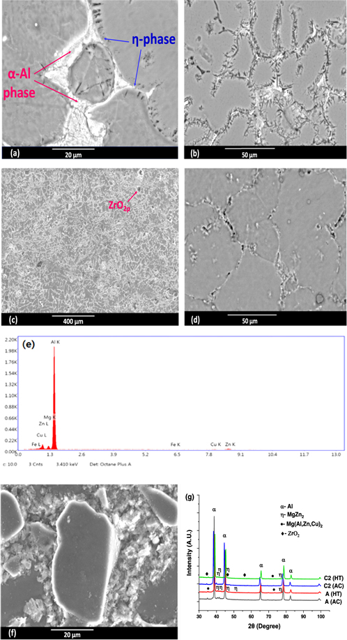
Figure 5. (a) Micrograph of AA7068 alloy depicting dendritic structure in as-cast condition, (b) AA7068 alloy during heat-treatment, (c) Composite revealing homogeneous dispersion of ZrO2p within the matrix phase in as-cast condition, (d) Composite in the heat-treated condition, (e) EDX analysis of AA7068 alloy, (f) Composite at higher magnification revealing robust matrix-ZrO2p interfacial bonding, and (g) Identification of distinct phases through XRD analysis.
Download figure:
Standard image High-resolution image3.2. Hardness behavior
The variation in the hardness of the concerned materials is represented in figure 6. Herein, it was noted that the hardness of the matrix alloy displayed remarkable improvement due to the addition of ZrO2p. Furthermore, the hardness of these materials further got improved when subjected to T6 heat treatment. The matrix alloy exhibited a hardness of 112 HV and 144 HV in as-cast (AC) and heat-treated (HT) conditions, respectively, which noticeably increased to 127 HV (AC) and 158 HV (HT) for composite with 2% ZrO2p and 147 HV (AC) and 180 HV (HT) with 4% ZrO2p, respectively. As a result, composite containing 4% ZrO2p in heat-treated conditions was observed with the highest hardness of 180 HV amongst all the concerned materials.

Figure 6. Hardness variation with respect to concerned materials.
Download figure:
Standard image High-resolution image3.3. Dry sliding wear attributes
3.3.1. Wear rate vis-à-vis applied pressure
Figure 7 represents the variation of wear rate in the AA7068 matrix and its composites in as-cast and heat-treated conditions with regard to applied normal pressure at a constant sliding speed of 3.5 m s−1. It was observed generically that the wear rate during earlier stages increased with increasing normal pressure, and a transition limit in all materials has existed at which the wear rate increased swiftly even with a modest upgrade in pressure. Furthermore, it was notable that the transition and seizure pressures for alloy were identical irrespective of condition, whereas the composites exhibited relatively greater transition and seizure pressures, which further increased with heat treatment.

Figure 7. Wear rate with regard to applied pressure ('s' signifies seizure).
Download figure:
Standard image High-resolution imageFor instance, as-cast alloy unveiled a wear rate of 4.02 × 10⁻³ mm3 m−1, and 5.802 × 10⁻³ mm3 m−1 at normal pressure of 0.5 MPa and 1.375 MPa, respectively, and thereafter it markedly increased to 9.307 × 10⁻³ mm3 m−1 at a normal pressure of 1.5 MPa, where it evidently got seized. A similar trend was detected for heat-treated alloy as well, where it displayed a wear rate of 3.809 × 10⁻³ mm3 m−1 and 4.792 × 10⁻³ mm3 m−1 at normal pressure of 0.5 MPa and 1.375 MPa, and beyond that pressure limit it has abruptly upsurged to 8.638 × 10⁻³ mm3 m−1 at 1.5 MPa, the seizure pressure causing unusual increased noise. In the case of the composite containing 2% ZrO2p, the wear rate was noticed to increase moderately up to a certain extent of applied pressure i.e., 1.5 MPa, however, beyond that, it increased at higher rates. For instance, an as-cast composite containing 2% ZrO2p displayed a wear rate of 2.962 × 10⁻³ mm3 m−1 and 4.831 × 10⁻³ mm3 m−1 for normal pressure of 0.5 MPa and 1.5 MPa, respectively, however it shot up to 7.962 × 10⁻³ mm3 m−1 at 1.75 MPa, the seizure pressure. A similar trend was noticed for heat-treated conditions as well, where at normal pressures of 1.75 MPa and 1.875 MPa, wear rate was detected as 5.443 × 10⁻³ mm3 m−1 and 6.99 × 10⁻³ mm3 m−1, respectively, and which further upsurged to 9.432 × 10⁻³ mm3 m−1 at 2.0 MPa, the seizure pressure. On the contrary, composite containing 4% ZrO2p had not displayed any substantial change in the wear rate even under seizure pressure when compared with the other two materials, nevertheless adhesion of mating surfaces and overshooting of temperature were evident in the meantime. For instance, an as-cast composite containing 4% ZrO2p exhibited a wear rate of 4.403 × 10⁻³ mm3 m−1 at 1.75 MPa and it increased merely to 5.95 × 10⁻³ mm3 m−1 under seizure pressure of 1.875 MPa. A similar trend was noticed for heat-treated conditions as well, where the wear rate increased from 4.887 × 10⁻³ mm3 m−1 to 6.055 × 10⁻³ mm3 m−1 when the applied pressure was transferred from 2.0 MPa to seizure pressure 2.125 MPa. Therefore, the seizure pressure in the composite containing 4% ZrO2p was identified to be improved over the composite containing 2% ZrO2p and matrix alloy. It was further detected that though the wear rate in matrix alloy was noticeably diminished during heat treatment, it had not any appreciable influence on seizure pressure. In the case of composites, a considerable change in the seizure pressure, as well as wear rate, was apparently detected owing to heat treatment.
3.3.2. Temperature rise vis-à-vis applied pressure
Figure 8 demonstrates the temperature variation in the vicinity of mating surfaces during sliding wear in as-cast and heat-treated conditions with regard to applied normal pressure. The temperature at the preliminary stages raised gradually with increasing normal pressure, and during the final stage, it raised abruptly to a noticeably greater value whenever applied pressure attained a critical value. This critical pressure value was recognized as the seizure pressure and the temperature at this pressure was termed seizure temperature.

Figure 8. Variation in temperature with respect to applied pressure ('s' signifies seizure).
Download figure:
Standard image High-resolution imageFor instance, as-cast alloy displayed temperatures varying from 35 °C to 59 °C for a normal pressure range of 0.5 MPa to 1.375 MPa, and afterward, the temperature noticeably raised to a higher value of 89 °C at 1.5 MPa. As well, the heat-treated alloy exhibited a resembling trend i.e., at 0.5 MPa and 1.375 MPa normal pressures, the temperature was recorded as 41 °C and 75 °C, respectively, while the temperature abruptly raised to 98 °C at the 1.5 MPa. Composite containing 2% ZrO2p displayed higher values of seizure temperature when compared with monolithic alloy irrespective of the condition. It was observed that the temperature at primary stages increased moderately with increasing applied pressure and then after upsurged rapidly and attained a steady state within a certain range of applied pressure. The temperature for the as-cast composite containing 2% ZrO2p was recorded as 39 °C and 46 °C at normal pressure of 0.5 MPa and 1 MPa, respectively, which further increased to 51 °C, 62 °C, and 66 °C at the pressure of 1.25 MPa, 1.375 MPa, and 1.5 MPa, respectively. Thereafter, the temperature suddenly increased to 87 °C and 116 °C for a normal pressure range of 1.625 MPa to 1.75 MPa. For heat-treated conditions, the temperature for a pressure range of 0.5 MPa to 1.625 MPa was recorded to vary from 42 °C to 85 °C, which again raised at a higher rate and varied in the temperature range of 106 °C to 121 °C for the pressure range of 1.75 MPa to 2 MPa. On the contrary, composite reinforced with 4% ZrO2p exhibited a mixed trend i.e., temperature fluctuating up and down at some instances with an increase in applied pressure, and varying with minor change for a certain range of applied pressure, and eventually reaching a higher value. In the as-cast condition, the temperature was measured as 59 °C, 57 °C, 68 °C, and 75 °C at 0.5 MPa, 1 MPa, 1.25 MPa, and 1.375 MPa, respectively, which further increased and varied within a narrow range of 95 °C to 103 °C for a pressure range of 1.5 MPa to 1.75 MPa. Then after it eventually increased abruptly to 135 °C when subjected to 1.875 MPa. Thus, 135 °C was detected as the maximum temperature during the seizure at 1.875 MPa. Whereas a somewhat dissimilar trend was noticed in heat-treated conditions i.e., maximum temperature reportedly got reduced during the seizure. In heat-treated condition, the temperature was measured to be 44 °C, 59 °C, 79 °C, and 87 °C for an applied pressure of 0.5 MPa, 1 MPa, 1.25 MPa, 1.375 MPa, respectively, and afterward, it varied within 108 °C to 125 °C for the pressure range of 1.5 MPa to 1.875 MPa. Thereafter, the temperature evidently overshot to 158 °C at 2 MPa, and finally reduced to 149 °C during the seizure at 2.125 MPa. As a result, it was realized that the maximum temperature of 158 °C occurred at 2 MPa, whereas a somewhat lower temperature of 149 °C was recorded during the seizure. Therefore, it is worth mentioning that the seizure temperature in this composite was the maximum temperature in the as-cast condition, while in the heat-treated condition, it was computed to be slightly lower than noticed at a formerly applied pressure.
3.3.3. Seizure pressure vis-à-vis concerned material
The variation of seizure pressure accompanying seizure temperature with respect to the concerned material is represented in figure 9. Wherein, a significant enhancement in the seizure pressure of monolithic alloy is evident due to the incorporation of ZrO2p. It was noticed that the matrix alloy was evidently seized when undergoing a normal pressure of 1.5 MPa, while the addition of 2 and 4% ZrO2p with the AA7068 matrix has effectively boosted the seizure resistance to 1.75 MPa and 1.875, respectively. Furthermore, as far as the heat treatment is concerned, the seizure resistance of monolithic alloy remained invariant during heat treatment, while the seizure resistances of composites were markedly enhanced to 2 MPa and 2.125 MPa, respectively. In addition to this, it is worth to mention that the seizure temperature shown in figure 8 is nothing but the maximum temperature recorded in all cases except for heat-treated composite containing 4% ZrO2p, where the maximum temperature was not detected at seizure pressure rather than before that.

Figure 9. Seizure pressure and temperature as a function of the concerned material.
Download figure:
Standard image High-resolution image3.4. Wear-out surface
The wear-out surface of AA7068 matrix alloy at a miner normal pressure of 0.5 MPa is represented in figure 10(a). It evidently depicts the scratched (damaged) portions, the evolution of relatively smooth MML, and the occurrence of continuous micro-grooves on the wear-out surface. Notably, it also signifies that the prevalence of crack formation is insignificant under lower normal pressure. Figure 10(b) shows the worn surface of the AA7068 matrix at an intermediate pressure of 1 MPa, wherein an array of multidirectional cracks (propagating parallel in transverse and longitudinal directions) is fairly visible, which in due course of time enables flaky shaped tiny wear residues (debris). Concurrent development and delamination of MML occur at this stage. Figure 10(c) dictates the seizure in the AA7068 alloy at 1.5 MPa, which comprises severely damaged portions detached from the upper surface, parallel lips, and paradigm-shifting of material in the direction of the sliding path. During the microanalysis of the worn surface during the seizure, it was noticed that burr formation took place at the edge of the test pin, which can be attributed to the shifting of a fraction of test material in the sliding direction due to immense frictional heating. The material gets softened due to frictional heating during the seizure and starts flowing in the sliding direction. Also, deep grooves and repeated wear ridges or adhesive spots (parallel lips) were detected at this juncture due to ploughing and experimentally recorded 'stick-slip' behavior (fluctuating nature) of friction process during the seizure [28]. In addition, the seizure in the alloy is also depicted more evidently through a micrograph taken at higher magnification as shown in figure 10(d), which clearly shows severe damage to the material, microcavity, and tearing in the material surface during the seizure. The worn surface of the composite containing ZrO2p under different pressure is shown in figures 10(e)–(h). Figure 10(e) portrays the worn surface of the composite at miner normal pressure of 0.5 MPa, which reveals the development of MML on the surface, micro grooves, and patches of moderately damaged portions. At an intermediate pressure of 1.5 MPa, the worn surface of the composite exhibits flaky shaped debris of worn surface that is essentially generated through the joining of multidirectional cracks propagating transversely as well as longitudinally, as shown in figure 10(f). It also signifies that the debris produced during this stage is more likely to separate from the worn surface. Figure 10(g) dictates the composite worn surface undergoing seizure at 2.125 MPa. It represents the breakage of MML, several parallel lips, microcavities, surficial cracks, tearing in the surface, and material flowing along the sliding path. The seizure in the composite containing ZrO2p in a better course has been described by the micrograph taken at higher magnification as shown in figure 10(h), wherein microgrooves with increased depth, transfer of material, and extremely scratched (damaged) portions are quite evident on the worn surface.
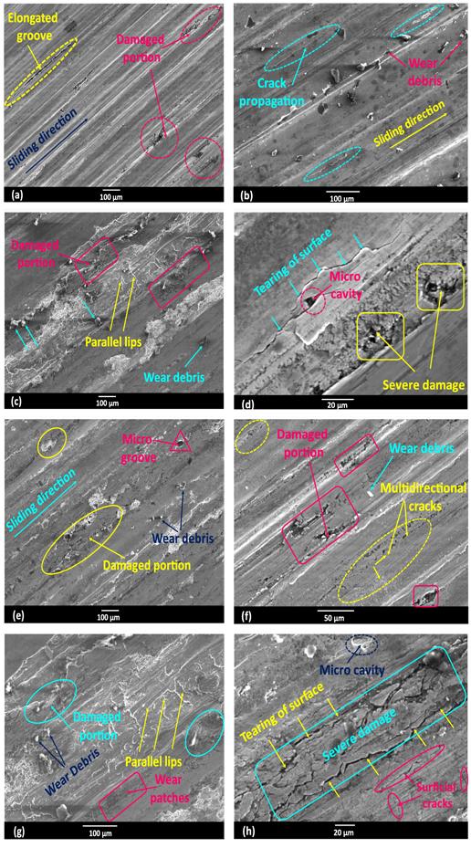
Figure 10. Typical micrograph of worn surface of (a) AA7068 matrix at 0.5 MPa, (b) AA7068 matrix at 1 MPa, (c) AA7068 matrix at 1.5 MPa (i.e., seizure pressure), (d) AA7068 matrix undergoing seizure at a higher magnification, (e) Composite containing 4% ZrO2p at 0.5 MPa, (f) Composite containing 4% ZrO2p at 1.5 MPa, (g) Composite containing 4% ZrO2p at 2.125 MPa (i.e., seizure pressure), (h) Composite containing ZrO2p undergoing seizure at a higher magnification.
Download figure:
Standard image High-resolution image3.5. Subsurface analysis
The subsurface of the AA7068 matrix generated at a minor pressure of 0.5 MPa is shown in figures 11(a) and (b). Figure 11(a) unveils sublayer exhibiting three distinct deforming zones i.e., (i) mechanically mixed layer (MML), (ii) severely plastically deformed zone (PDZ), and (iii) undeformed zone (UDZ) displaying negligible microstructural change. Herein, MML and PDZ pose thickness of around 38 μm and 42 μm, respectively. At the junction of highly PDZ and UDZ, cracks are generated which propagate longitudinally, and meanwhile, the PDZ gets transformed into MML. Subsequently, the MML experiencing sliding wear is detached from the surface and produces tiny wear residues (debris). The softer Al grains in PDZ during sliding action are also evident in figure 11(a), which flow along the sliding path. Figure 11(b) depicts the subsurface of the AA7068 matrix experiencing the seizure at 1.5 MPa. It reveals deforming zones similar to the earlier case of i.e., MML, PDZ, and UDZ. It dictates that the depth of deforming zone is noticeably extended during the seizure. The depth of deformation in the AA7068 matrix at 0.5 MPa pressure is noted to be 78 μm, whereas it is noticeably extended to 142 μm due to the seizure. Therefore, it can be pronounced that by increasing the normal pressure to seizure pressure, the degree of deformation gets boosted. The subsurface in the composite containing ZrO2p evidently exhibits crack formation and propagation, and various deforming zones i.e., MML, severely PDZ, and bulk UDZ. The subsurface of the composite containing 2 and 4% ZrO2p at 0.5 MPa is depicted in figures 11(c) and (d), respectively. Herein, MML consists of ZrO2p and poses a thickness of around 32 μm and 29 μm for composite containing 2 and 4% ZrO2p, respectively. Subsequently, a severely PDZ posing a thickness of around 40 μm and 36 μm is evident just below the MML in these composites. A demarcating layer of negligible thickness can also be seen between the severely PDZ and UDZ in such cases. It is noteworthy that ZrO2p present at this juncture is still kept intact with the layer and no fragmentation is noticed during this stage. Afterward, increasing the pressure to the seizure pressure of 2 MPa and 2.125 MPa, the depth of deformation in both the composites is observed to be increased as depicted in figures 11(e) and (f). It is detected that the level of subsurface deformation under seizure is extended to 125 μm and 114 μm for composite with 2 and 4% ZrO2p, respectively. Nucleation and propagation of multidirectional cracks are also evident in severely PDZ. It is also notable that ZrO2p is present in the severely PDZ which have not faced any type of debonding or pulling out action. The compositional characterization of the subsurfaces was carried out through EDX analysis, as represented in figures 11(g)–(i). The EDX spectrum of the alloy during the seizure is represented in figure 11(g), which confirms the presence of the Fe element with a concentration of 30.95% over and above the bulk elements of the pin material. This suggests that the test material is efficient in transferring the counter disc material (Fe) to the pin material during the seizure. Furthermore, it is also notable that the concentration of Fe element in composite was increased from 17.51% to 27.11% with increasing normal load to the seizure load, which signifies that Fe content in the MML was progressively increasing as well. Along with Fe, the O element was also evident in the composite EDX spectrum shown in figures 11(h) and (i), which must be existing in the form of oxide. The presence of the O element confirms the formation of a thin oxide layer onto the worn surface. Though it is not clear whether it is an iron oxide or not, it might be signifying the oxidative type of wear at the instances. The emergence of an oxidized layer during the sliding wear was also observed in the studies [29, 30].

Download figure:
Standard image High-resolution image
Figure 11. Subsurface micrograph of (a) AA7068 matrix at 0.5 MPa, (b) AA7068 matrix undergoing seizure at 1.5 MPa, (c) Composite containing 2% ZrO2p at 0.5 MPa, (d) Composite containing 4% ZrO2p at 0.5 MPa, (e) Composite containing 2% ZrO2p undergoing seizure at 2 MPa, (f) Composite containing 4% ZrO2p undergoing seizure at 2.125 MPa, (g) EDX spectrum of alloy suggesting counter surface material (Fe) transfer to the pin during seizure, and EDX spectrum of composite at (h) lower load, and (i) seizure, signifying counter material transfer (Fe) and formation of thin oxidized layer.
Download figure:
Standard image High-resolution imageIn view of the magnitude of wear attributes of the concerned materials, it can be pronounced that the as-cast condition integrated with seizure pressure is the stage at which the subsurface is most vulnerable to deformation. Therefore, the microhardness of each subsurface has been evaluated in as-cast condition and under seizure pressure of that particular material. Figure 12 describes the deviation in microhardness from the bulk hardness of the parent material at seizure concerning the depth of deformation in a direction vertical to the wear-out surface. It was noticed that in microhardness variation regarding the depth of subsurface from the worn end followed different patterns for alloy and composites. Microhardness variation was classified in three different regimes i.e., Regime (i)–(iii). It was observed that the matrix alloy displayed a microhardness of 148 HV just below the worn end, which steadily decreased up to a depth of 80 μm under Regime (i), and thereafter it increased up to a depth of 120 μm under Regime (ii). The microhardness was found continually diminishing after a depth of 160 μm and subsequently stabilized at 180 μm, signifying Regime (iii). On the contrary, the microhardness variation in both the composites was observed to be more or less analogous to each other. Indeed, microhardness at the location adjoining to the worn end was detected to be 174 HV and 177 HV for composite embedded with 2 and 4% ZrO2p, respectively, which in due course stabilized at a depth of 160 μm from the worn end. Meanwhile, a substantial decay in hardness was noticed in both the composites up to a depth of 100 μm under Regime (i). While, the microhardness within the depth of 100 μm to 160 μm decreased moderately under Regime (ii), and afterward got stabilized after a depth of 160 μm at the advent of Regime (iii). Therefore, it is noteworthy that the extent of deformation along the plane normal to the wear surface has been significantly suppressed due to the presence of reinforcing ZrO2p.

Figure 12. Microhardness variation in the subsurface concerning the depth from the worn end.
Download figure:
Standard image High-resolution image4. Discussion
4.1. Microstructure
The Al-Zn(-Mg) matrix alloy displays a rosette-like structure of primary α-Al grain solid solution covered by inter-dendritic secondary phases. It is noteworthy that the solubility level of η-compound for copper (Cu) is comparatively greater, which gets detected within the eutectic zone. Additionally, EDX and XRD analysis of the AA7068 matrix alloy displays the presence of intermetallic compound MgZn2, which specifies that Mg and Zn elements are relatively greater over the typical chemical composition of the matrix. It is apparent that the compound MgZn2 has dissolved the Cu and Al constituents and evolved into the compound Mg(Al,Zn,Cu)2, which has decent agreement with the study [31]. The segregation of the solute elements that happened while ultrasonic casting resulted in more Cu, Zn, and Mg elements around the inter-dendritic eutectic zones. It is remarkable that during the solidification, the lower diffusion velocity of Cu over Mg and Zn resulted in a greater concentration of Cu in eutectic zones. The propelling force accountable for the transformation of phases from Mg(Al,Zn,Cu)2 to Al2CuMg must be the supersaturation of Cu inside the eutectic zones, which offers more stability to the Al2CuMg phase. The plate-shaped (needle) microstructure of the alloy phase gets transformed into a spherical or globular shape when subjected to T6 heat treatment. Besides, the formation of secondary phase precipitates during heat treatment and their uniform distribution along the grain boundary can be reasonably seen in the micrograph. The composite micrograph reveals a noteworthy change in the dendritic morphology of monolithic alloy after the induction of ZrO2 particulates. The uniform dispersion of the induced particles within the matrix phase is noticeable in the micrographs shown in figures 5(c) and (d), which can be realized due to the presence of secondary grain refining agents such as Zr (ZrO2p) along with ultrasonic agitator during fabrication may provide more grain boundaries and consequently enable boosted homogeneous dispersion of intermetallic compounds. Figure 5(f) reveals a robust matrix-particle interface with no defects such as interfacial reactions or porosity. The ZrO2 particle is tightly bonded with the matrix material, which signifies a good interfacial bonding between the two constituents. A proper bonding and a reaction-free interface between particle and matrix may lead to enhanced mechanical and tribological properties [32]. Also, it is worth mentioning that the melting point of the AA7068 matrix alloy and ZrO2 ceramic particle is around 635 °C and 2700 °C, respectively. During the T6 heat treatment, only the formation of precipitates and phase changes occur, and there is no softening in the matrix. Thereby, no loosening of ZrO2 particles within the composite during the heat-treatment process.
4.2. Hardness
The improved hardness of matrix alloy due to ZrO2p can be accredited to the incorporation of hard ceramic particulates of higher density into the matrix, which creates greater constraints on plastic deformation [33]. Moreover, the density of dispersoids, fluidity of the molten alloy, solidification rate, and dispersion of dispersoids into the matrix phase might be the foremost factors prompting the hardness of the composites [34]. A study, [35] conveyed a considerable enhancement in the hardness of the Al matrix after the induction of harder and stiffer ceramics. Likewise, the discrete lattice model established by [36] displayed that the dispersion of harder ceramic particles decreased the wear rate in the composites by improving the hardness. During the hardness measurement, when the load is applied through the indenter onto the surface of the composite containing hard particles, the load gets transferred onto these particles and supported by these particles. Besides, geometric constraint to the plastic deformation is also created by these particles, and geometrically dislocations are piled up to accommodate the deformation by load application. This results in increased dislocation density and leads to dislocation hardening in the composites [37]. This can also be explained by the fact that the hard dispersoids enable protection for the softer Al matrix phase, and thus, restrict the distortion and cutting of the slides and limit indentation onto the composite surface, which in turn results in enhanced hardness for the composites [38].
Furthermore, evolution of extremely small homogeneously distributed secondary precipitates can be attributed to the hardness improvement in heat-treated materials. The micro mechanisms that govern the hardening characteristics of age hardened alloys are determined by the coherency and distribution of precipitates, grain size and shape, grain boundary precipitates, and the presence of other second phase particles caused by impurities. For an Al-Zn-Mg alloy aged at temperatures below the (Guinier-Preston) GP zone solvus, the following precipitation sequence has been identified: nearly spherical GP (I, II) zones → η'-MgZn2→η-MgZn2 [39]. The GP (I) and GP (II) zones that are coherent with the matrix may arise in the early stages of aging, i.e., after room temperature aging or short period aging at higher temperatures. The most common form of GP zone during natural aging is GP (I). The GP (II) zone is believed to occur before the creation of η'-phase and is linked to vacancy-rich clusters that develop during quenching after solution treatment. By nucleating at existing precipitates, the transition to η-phase happens directly [40–42]. More specifically, it has been found that the Al-Zn-Mg alloy system only comprises GP zones for lesser aging times, however it also contains η'-η particles for longer times [43]. The variation in the stress fields in the region of the precipitate determines the degree of hardening. In contrast to Al-Cu alloys, no coherency stress effects around precipitates were observed in Al-Zn-Mg alloys; the MgZn2 lattice differs too much from the matrix for full coherency to be maintained. The hardening effect in commercial Al-Zn-Mg alloys is thus mostly due to the dispersion of fine metastable η' particles in the matrix, rather than internal coherency stresses. It is also perceived that if GP zones reach a size that is stable at the aging temperature, they will develop and change into η' particles with an average size and spacing, allowing the materials to be strengthened [44]. The formation of intermetallic precipitates such as MgZn2 (η-phase) and Al2Cu providing greater hardening through the pinning effect on the grain boundaries [45]. As a result, the uniform dispersion of fine η/η'-MgZn2 intermetallic phases along with reinforcing ZrO2p impede the dislocation motion, imparting greater hardness and consequently improved wear resistance to the materials.
4.3. Wear attributes vis-à-vis applied pressure
The resistance to wear (scratching or abrasion) in a composite generically is the measure of the ability to confine the secondary reinforcing particulates induced into the matrix phase. This greatly depends on the anchoring and contraction forces between the matrix and reinforcing materials. It can also be noticed that because of heat treatment, the precipitates are formed which results in strengthening of the matrix as well as enhancement in capacity to withstand the reinforcing agent. Therefore, the resistance to wear has been observed to be improved due to the adoption of heat treatment as presented in figure 7.
There exists a relative motion between two counteracting surfaces (faces) while sliding under shear as well as normal load. It can be quite perceptible that all of these interacting surfaces may not be flawlessly smooth as they exhibit an abundance of asperities with uneven nature. These asperities essentially differ in the geometry i.e., shape and size (height), and severity even in the same material. The distribution of asperity heights generically obeys a somewhat Gaussian-like distribution. The asperities with greater height may penetrate relatively deeper onto the surface of the soft material, whereas a part of the asperities of softer along with harder faces adjust making contact altogether and also may touch. In figure 7, the wear rate increases with an increase in the applied pressure, which can be primarily attributed to the fact that with increasing applied pressure, the penetration of harder counter face asperities to the relatively softer pin specimen increases, and subsequently permits the fracture and deformation of softer surface asperities. It has also been observed that till a certain extent of applied pressure, the wear rate rises more or less linearly prior to the seizure, nevertheless, the increment rate of wear within this applied pressure range has not been detected to be much extensive. Thereafter, increasing normal pressure up to a critical limit, the frictional heating comes into a vital play which consequently increases the regional adhesion between the counter and pin surfaces. Additionally, in due course of time penetration of the asperities also gets increased marginally due to the softening of the surficial material. During this stage, the weight loss because of the disintegration (delamination) at the adhered regions, and micro-cutting and fracturing get magnified markedly, which in turn results in the annihilation of MML establishing at minor normal pressure. Then, beyond the critical pressure, a paradigm shift in increment rate of wear happens i.e., from linear to hasty wear rate. Meanwhile, owing to the rise in temperature following evidence can be perceived; (a) softening of surficial material, (b) larger deformation in mating surface accompanying subsurface, (c) surficial oxidation, and (d) creation of MML. Herein, the existence of most of these facts is fairly significant before the seizure, however, a greater level of softening of material and an abundant annihilation of MML or oxide layer correspond to seizure. This in turn results in more soundly adherence between the pin specimen and the counteracting surface and thereby requires more energy to subjugate the bond between adhered mating faces. This permits the abrupt rise in temperature of the pin specimen as depicted in figure 8. Furthermore, pin specimen exhibits sharper and stronger asperities during low normal pressure which get deformed and fractured with increasing applied pressure. This results in healthier interaction between the counteracting asperities of pin specimen and counterface when subjected to miner normal pressure. Meanwhile, the following facts might be occurring at higher normal pressure; (a) deformation of asperities leading to fracture/fragmentation, (b) deeper penetration of asperities, (c) greater displacement of material between the mating faces during deformation, (d) higher temperature increment leading to more softening in material, and (e) establishment of MML with more thickness.
The composites containing ZrO2p exhibit enhanced resistance to seizure and wear in comparison to the AA7068 matrix regardless of all normal pressures, which is principally due to the fact that dispersion of hard ceramic particulates imparts plastic constraints in the base alloy and offers high-temperature strength. As well, the hard ceramic dispersoids being present on the composite surface act as protruded (projected) elements and secure the alloy phase against the severely contacting disc surface, therefore ensuring reduced wear rate and increased temperature in composites over the AA7068 matrix phase. Moreover, it has also been realized that at miner normal pressure, a relatively thin oxide layer is formed during sliding action, which leads to the oxidational type of wear. Whereas, during the application of higher normal pressure, MML is being developed which in successive times gets disintegrated leading to the delaminating type of wear. Indeed, superior seizure and wear resistance in the concerned materials can be significantly imparted, provided that this oxide layer and MML are made to be more robust. The seizure resistance of the alloy has remained unaltered during heat treatment, which can be described due to the insignificant impact of heat treatment on the high-temperature flowability in the virgin alloy. A greater asperity-to-asperity interface and a deeper level of asperity penetration result in higher friction coefficient at minor normal pressure. The depth of asperity penetration may enhance at greater normal pressure, however simultaneously smoothening in the contact surfaces is also imparted through the material transfer at the surfaces of mating faces. Even if the surficial smoothness increases circumstantially, the pin specimen material becomes softer and starts behaving analogous to a viscous fluid, and consequently induces the slipping phenomenon. This in turn leads to a decreased temperature in some instances in figure 8 with increasing applied pressure.
4.4. Governing wear mechanism in accordance with wear surface and subsurface
The operative wear mechanism indulged in the dry sliding wear of AA7068 matrix alloy and composite embedded with ZrO2p against the counter steel disc surface can be schematically understood below through different stages shown in figures 13 and 14, respectively. It evidently signifies the displacement (transfer) of counterface material towards the MML, which happens relatively massively in composites over the matrix alloy, and the extent of such material transfer with increasing normal pressure. The sublayer or MML in the case of composites exhibits greater hardness variation when compared with the matrix alloy undergoing seizure, as shown in figure 12, which enables superior ability in composites to withstand higher temperature and applied pressure. It is also remarkable that at the point of the seizure, an unstable MML is realized which eventually gets annihilated from the surface of the pin specimen. Additionally, any trace of MML on the pin specimen surface is very scarce during the microanalysis of the wear surface and subsurface of the concerned materials. In figure 12, a substantial deviation in microhardness from the bulk hardness of parent material is detected up to a depth of 100 μm under Regime 1, which is credited to the evolution of harder MML on the pin surface. A moderately increased microhardness under Regime 2 is due to the shear deformation, shear instability, and nucleation and growth of voids occurring in the sublayer. The character shown by the subsurface in this study has a decent agreement with observations made by Venkatraman et al [25], where turbulent plastic flow caused by shear instability resulted in MML formation up to a certain depth under the worn surface. The stabilization of microhardness under Regime 3 is due to the advent of the undeformed zone with inconsequential microstructure change. During Regime 3, the complete annihilation of MML has been observed, and this could also be another reason for stabilized microhardness values.

Figure. 13. Stage (1–5) gesticulating the governing wear mechanism in matrix alloy.
Download figure:
Standard image High-resolution image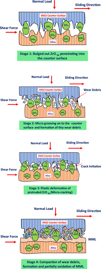
Download figure:
Standard image High-resolution image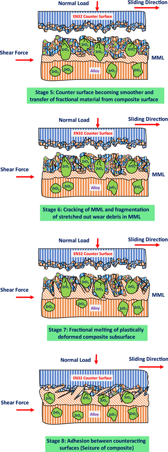
Figure 14. Stage (1–8) gesticulating the governing wear mechanism in composites containing ZrO2p.
Download figure:
Standard image High-resolution image
The governing wear mechanism causing material removal in matrix alloy is schematically portrayed in figure 13 (stage 1–5). Wherein, Stage 1: describes the asperity-to-asperity interaction during the initial stages of wear in the case of alloy. These asperities partly get in touch via their tips, while the surficial asperities posing higher peaks offer deeper penetration onto the relatively softer face. Additionally, few of the asperities of the mating surfaces interact along their sidewalls. Stage 2: depicts the onset of permanent (plastic) deformation near to subsurface, resulting in the orientation of wear debris elements along the sliding path and permanent deformation close to the mating zone of asperities. This stage also displays the micro-grooves occurring as a result of scratching of asperities onto the counteracting face and emergence of tiny wear debris because of fracture of some asperities. Stage 3: indicates the compaction of tiny wear residues (debris) on the surface of pin specimen generating MML and plentiful subsurface deformation causing arrangement of microconstituents (precipitates) towards sliding direction. Stage 4: gestures the fractional melting of subsurface section i.e., the commencement of seizure, that is being produced due to the fracture and delamination of the MML and subsequently bared to the mating faces. Rather, the valleys present in the asperities of communicating faces eventually accumulated by the material relocated from the pin specimen. Stage 5: gesticulates the removal of MML from the pin surface. It also describes the flow of the fractionally molten subsurface material over the wear-out surface and its adherence against the counterface, permitting seizure in the case of matrix alloy. The wear-out surface undergoing seizure exhibits material to flow onto the pin surface which resembles the wave motion.
Figure 14 (stage 1–8) schematically describes the wear mechanism operating in composites embedded with ZrO2p undergoing dry sliding wear. Herein, Stage 1: displays the interface between the composite pin surface and counter steel surface experiencing the motion of one face with respect to another counterface under applied normal pressure. This stage also depicts mutual interaction of the asperities of matrix alloy and counter steel face, counter surface asperities of higher peaks penetrating onto alloy phase, and ZrO2p bulging out and penetrating the counteracting surface. Stage 2: denotes breakage of severe asperities resulting in tiny wear residues. Stage 3: gestures micro cracking in bulged ZrO2p, the advent of the plentiful amount of equiaxed and extended tiny wear residues being lodged on the mating surfaces, and plastic deformation at the subsurface zone. Stage 4: articulates the compaction of fine wear debris near contacting surfaces, leading to the formation of MML onto the composite surface and somewhat material transfer towards the counter surface. The MML in the case of composites is composed of fractionally oxidized, extended, and equiaxed tiny wear debris produced through counteracting surface and matrix phase accompanied by fine ZrO2p. Stage 5: signifies smoothening in the counteracting face and accommodation of a certain quantity of material transported from the pin specimen of composite. Whenever the generated MML meets the counterface, the relocated material can be anticipated to behave like the MML. The MML in the composite is discontinuous near the region containing ZrO2p. Stage 6: reveals the cracking in the MML near the boundary of the compacted debris and fragmentation of stretched-out fine wear residues onto the MML. Stage 7: denotes the permanent deformation in the subsurface and partly molten subsurface (sublayer) flowing through the cracks generated underneath the MML. Herein, the cracks in the MML are enabled by the upthrust offered due to the movement of the partly molten sublayer movement, and the thermal mismatch of the sublayer with the MML. The MML eventually gets fractured and disintegrated from the worn material and a partly molten sublayer touches directly the counterface. Stage 8: gesticulates the flow of fractionally melted sublayer originating via the branches of cracks present in the MML. It also represents the flow of somewhat molten material over the composite pin specimen, which nearly resembles wave motion and afterward gets adhered against the counteracting steel face. Additionally, it displays that the existence of ZrO2p hinders the movement of partly molten sublayer, and consequently penetrating onto the counteracting surface. The seizure in composites is recognized at this stage.
5. Conclusions
In consideration of the present experimentation, the following key remarks can be drawn;
- I.The micrographs of cast materials unveiled that the enhanced ultrasonic-assisted stir-squeeze casting route has enabled castings with superior quality i.e., free from pores and agglomeration of particles.
- II.The composite containing 4% ZrO2p enhanced hardness by 31.25% (AC) and 25% (HT) over the monolithic AA7068 alloy.
- III.The composites yielded a diminishing wear rate due to the dispersion of ZrO2p. The wear rate at preliminary stages increased when the normal pressure is increased, and a transition limit existed for all the materials beyond which it upsurged abruptly to a very higher value when undergoing the seizure. Besides, heat treatment has also lowered the wear rate irrespective of the material composition.
- IV.The seizure resistance of matrix alloy was enhanced by 16.7% and 25% due to the incorporation of 2 and 4% ZrO2p, respectively. Furthermore, the seizure resistance of these composites was also boosted by 14.3% and 13.33% respectively when undergoing heat treatment.
- V.The temperature due to frictional heating initially increased moderately with increasing normal pressure, and thereafter overshot hastily to a greater value during the seizure. The composites unveiled higher temperature rise when compared with monolithic alloy, wherein, composite containing 4% ZrO2p displayed the greatest rise in temperature by 61.22% and 51.7% over matrix alloy at heat-treated and as-cast conditions, respectively.
- VI.Mechanically mixed layer (MML), continuous grooves, and somewhere severely scratched zones were consequenced onto the wear-out surfaces of the concerned materials at miner normal pressures. An array of multidirectional cracks (resembling longitudinal and transverse), movement of these multidirectional cracks, and some damaged zones were evident, which led to the generation of flaky shaped wear residues, and simultaneous establishment and separation of the MML under intermediate normal pressure. Whereas, breakage of the MML resembling wave motion in the direction of sliding, and parallel lips were the prime wear carriers during the application of higher normal pressure or seizure.
- VII.In comparison to base alloy, thicker MML was created on the composite surfaces, however, these MMLs were more discontinuous due to the presence of ZrO2p composites. The hard ZrO2p dispersoids empowered scratching action over the MML and consequently instigated micro grooves and cavities onto the MML in worn composite surfaces.
- VIII.The subsurface study unveiled that; (a) the extent of deformation got suppressed due to the presence of ZrO2p, (b) thickness of MML (the deforming zone) increased at higher normal pressures, (c) Al grains were identified flowing in the direction of sliding, (d) the micropores have emerged at the Al dendritic and intermetallic phase interface, and fitting together of such voids resulted in the development of multidirectional cracks, which in the meantime produced tiny wear residues.
Acknowledgments
The authors extend their sincere gratitude to MANIT, Bhopal (India) for fostering research and development, Dr S Das (Former Director, AMPRI-CSIR, Bhopal/Adjunct Professor, MANIT-Bhopal) for sharing his valuable expertise, and IIT-Kanpur for providing technical assistance to complete this research work.
Data availability statement
All data that support the findings of this study are included within the article (and any supplementary files).
Funding
None.
Conflict of interests
No conflict of interests.