
Abstract
There has been a recent surge in interest for optical satellite communication (SatCom) utilizing lasers. It is clear to see why, as optical SatCom is capable of higher speed, lighter weight, higher directionality, and higher efficiency versus their radio-based counterparts. Research into optical SatCom has focused on devices operating in the short-wave infrared (SWIR), which is due to the maturity and commercial availability of such component's thanks to significant development in terrestrial telecommunications networks. However, SWIR performs poorly in fog and heavy weather, prompting investigations into longer mid-wave and long-wave infrared bands for optical communication instead due to reduced atmospheric losses. This paper provides a comprehensive review of laser transmitters, detectors, and the science behind selecting longer wavelengths for optical SatCom to boost optical SatCom between ground stations and low earth orbit satellite constellations being deployed.
Export citation and abstract BibTeX RIS

Original content from this work may be used under the terms of the Creative Commons Attribution 4.0 license. Any further distribution of this work must maintain attribution to the author(s) and the title of the work, journal citation and DOI.
1. Introduction
Optical satellite communication (SatCom) has the potential to greatly increase the bandwidth available over that provided by traditional radio-based payloads currently in orbit. Increasing SatCom bandwidth has become more of a priority in recent years as the volume of data collected by satellites continues to grow as we develop more complicated payloads, especially when missions include capturing high-resolution images of Earth and the cosmos from NASA and other space agencies around the globe. There has been a boom in commercial interest as well, with companies like Google, Telesat, Starlink and more currently pursuing satellite constellations based on inter-satellite laser links, with potential for laser-based ground links in the future. With all this interest in the research and commercial sectors, it is no wonder that free space optical (FSO) communication has become a hot topic in the last decade, with a number of high-profile missions testing the feasibility of laser communication in space.
In the past 20 years, there have been several proof-of-concept missions undertaken by multiple space agencies to test the feasibility of optical SatCom. The first intersatellite link was demonstrated by Artemis and SPOT 4 in 2001 [1]. In 2008, the European Space Agency demonstrated from satellite to ground with the TerraSAR-X and NFIRE satellites [2]. More recently, in 2013 NASA successfully transmitted an image of the Mona Lisa to the Lunar Reconnaissance Orbiter using optical links [3]. In 2014 NASA's OPALS was able to achieve a 400 Mbps link and re-acquire tracking after weather caused the link to drop [4]. In 2014, the NICT carried out the first low earth orbit to ground laser link using their onboard Small Optical TrAnsponder [5]. In 2020, Japan Aerospace Exploration Agency (JAXA) successfully demonstrated a bidirectional ground to satellite link on their Small Optical Link for International Space Station (SOLISS) mission [6]. In the near future, the NICT will demonstrate a GEO link to ground at speeds up to 10 Gbps using their High-speed Communication with Advanced Laser Instrument terminal aboard the ETS-9 satellite [7]. While there are many more missions to choose from, these should serve as representative examples and demonstrate that interest in the field is strong.
Any optical SatCom link contains a transmitter and a receiver. In a ground-to-satellite scenario, the receiver is typically a telescope at a ground station outfitted with optical filters to remove background noise, a high speed and high sensitivity detector, a demodulator, and some controlling circuitry to correct for pointing errors in real time. A transmitter typically consists of a laser source, a modulator, a telescope, and typically a receiver for a laser beacon from the ground station to aid with decreasing pointing errors. Another important consideration is the atmospheric channel, which will induce losses from absorption, scattering, and atmospheric turbulence as the light travels from the satellite to the ground station or vice versa. We must carefully consider the wavelength selected for transmission, as there are multiple atmospheric transmission windows to choose from. As a result, we must cover the theory behind wavelength selection for SatCom, and why one might choose certain wavelengths over others. The most important component for the transmitter is the laser source, as this determines the output power, modulation speed, and wavelength for the transmitter, all of which are important factors when modelling the optical link. Additionally, detector technology varies significantly across the atmospheric transmission bands, and the figures of merit for detectors such as detectivity, bandwidth, and responsivity determine the minimum detectable power and communication speed that can be achieved. Therefore, we will focus on laser sources, detectors, and the justification for choosing longer wavelength components in this review.
One common thread between all the SatCom demonstrations to date has been their use of the short-wave infrared (SWIR) wavelength band. This band spans roughly 0.8–1.7 µm and is one of four main atmospheric transmission windows where absorption due to the atmosphere is low. The popularity of SWIR is due to the relative maturity and commercial availability of laser transmitters capable of high-speed modulation, such as Nd:YAG, Nd:YVO4, and distributed feedback (DFB) C-band semiconductor lasers that can be amplified using erbium doped fiber amplifiers (EDFAs). Due to significant research and development in the telecommunications industry, it is possible to obtain watt-level output power and gigabit speeds for a relatively affordable price. The only drawback of SWIR-based communication is that any weather more severe than light to moderate fog induces significant attenuation in the link, potentially reducing signal availability [8]. One possible mitigation technique that is being examined is to move to the mid-wave (MWIR (3–5 µm)) and long-wave infrared (LWIR (8–14 µm)) bands, as there is evidence from terrestrial experiments that these wavelengths experience significantly less attenuation from weather and atmospheric effects. Although this could increase availability and reliability for optical SatCom, to the best of our knowledge there has not been a comprehensive review of the suitability of MWIR and LWIR optical components for satellite links.
The goal of this paper is to evaluate the suitability of current state-of-the-art MWIR and LWIR lasers and detectors for optical SatCom according to the requirements of the Canadian Optical SatCom Consortium (OSC). The OSC was founded in 2019 by the Government of Canada via the National Research Council of Canada (NRC) [9]. The OSC is made-up of many Canadian universities and companies with the goal of advancing research in photonics for SatCom. One of the main goals of the OSC is to attain reliable links capable of at least 1 Gbps across Canada. Figure 1 illustrates a high-level overview of the intended optical SatCom system.

Figure 1. A high-level overview of the intended final communication system from the OSC.
Download figure:
Standard image High-resolution imageAs a result, this is the minimum requirement that must be met by MWIR and LWIR photonic components to be considered viable for optical SatCom. This will be evaluated by comparing to previous successful SWIR missions and calculating a link budget using Optiwave's OptiSystem simulation software to determine if such links are viable. The structure of this paper is as follows: in section 2, a summary of the theory of optical propagation through the atmosphere, as well as a review of experimental data on communication links in the SWIR, MWIR, and LWIR. In section 3, a review on laser sources, covering four main laser technologies relevant to optical SatCom in the SWIR, MWIR, and LWIR, concluded with a table summarizing typical performance metrics for each class of laser. In section 4, a review of photodetectors, covering multiple types of detector technology and comparing their relevant performance metrics for the MWIR and LWIR, as well as a brief discussion on promising up and coming detectors. In section 5, there is a link budget calculation for each wavelength band, and a conclusion is drawn on the suitability of MWIR and LWIR for SatCom.
2. Wavelength selection
There are three main factors that impede an optical link: scattering, absorption, and local variations in the refractive index (otherwise known as scintillation). All three are heavily dependent on wavelength, which means the wavelength of the link can be optimized for ground and satellite-based links. In general, it is assumed in the following discussion that the relevant links are bi-directional ground to satellite or ground to ground links. The three main wavelength bands discussed in this work correspond to the three main atmospheric transmission windows, where absorption is low, and transmission of the given wavelengths are high. The visible spectrum is also ignored, as eye safety concerns have made this approach to FSO communication undesirable, especially when the SWIR offers equal if not better performance while providing less of a safety hazard. We will discuss the advantages and disadvantages of the different transmission windows, mainly focusing on the tradeoff between the improved link performance in heavy weather versus the difficulty in obtaining high quality components operating in the respective transmission window.
2.1. Background theory
It is important to start with some background information that is common to all the wavelengths being discussed. We will consider the free space channel impairments that affect all optical channels and introduce their dependence on wavelength where relevant. This way, we can reference the formulas and theory presented in this overview when discussing the different wavelengths to see why some wavelengths may be beneficial for FSO communication. We will cover three significant channel impairments that an FSO link will encounter: beam divergence, atmospheric attenuation, and atmospheric turbulence. While pointing error is also a significant consideration in optical links, it is usually accounted for by modifying the divergence angle of the beam, and so any wavelength dependence of pointing error is sufficiently described by considering beam spreading error. If desired, a more in-depth discussion on pointing error can be found in [10].
2.1.1. Beam spreading.
The beam divergence of a laser beam is an inherent property of light due to the quantum nature of light and the fact that most lasers originate from an aperture with finite size. We can characterize the divergence of a laser beam using several parameters, such as the Rayleigh range or the waist size of the beam. The Rayleigh length of a laser depends on the size of the beam waist and the profile of the beam itself. While there are several laser profiles that have been created in laboratories, the most common beam profile for an FSO laser is that of a Gaussian beam. A Gaussian beam is characterized by an irradiance profile that follows a Gaussian distribution, with intensity highest in the center of the beam and decreasing as the radius from the center of the beam increases. The properties of a Gaussian beam are well defined, with the Rayleigh range zr being as a function of the beam waist radius  and the wavelength of the light
  :
:
We can also determine the beam radius of the Gaussian at some distance from the waist  if the beam waist or Rayleigh range is known:
Sometimes it is desirable to instead define the divergence as an angle in radians, which is also a well-defined property of Gaussian beams:
We see that longer wavelengths lead to higher divergence angles, and the size of the beam waist is inversely proportional to the amount of divergence, with large beam waists resulting in low divergence and vice versa. The beam divergence affects how much of the beam is clipped at the detector, as the beam will almost certainly diverge to the point that much of the original beam will miss the detector on the ground for a satellite downlink. Typically, the achievable data rate is a strong function of the divergence angle, as shown in the following formula for data rate in bits per second (bps) [11]:
where Pt is optical power at the transmitter,  is the transmitter efficiency,
  is the receiver efficiency, Ep is the photon energy, Np is the receiver sensitivity in photons per bit, L is link distance, latm is atmospheric losses in dB, and Dr is the receiver aperture diameter. From this, we can draw the conclusion that lower divergence angles are desirable, and longer wavelengths will suffer from larger beam divergence over a given propagation distance versus shorter wavelengths if everything else in the system is held constant. The other conclusion we can draw is that if we wish to use longer wavelengths to mitigate the effect of weather and atmospheric turbulence, it may be necessary to use larger transmitting and receiving telescopes to increase the gain to make up for the loss due to larger beam divergence.
2.1.2. Atmospheric turbulence.
The next channel impairment to discuss is atmospheric turbulence, sometimes referred to as atmospheric scintillation. This is caused by local gradients in the air temperature or pressure of the atmosphere, causing small changes to the refractive index that distort the beam over long propagation distances. One of the main accepted models for atmospheric turbulence is the Kolmogorov model, which ties the local temperature changes to changes in the refractive index. As a laser beam propagates through the regions of changing refractive index, it suffers from intensity fluctuations and wavefront distortions [12]. The size of these cells is characterized by two values: the inner scale  (on the order of millimeters) and the outer scale
  on the order of meters. The outer scale turbulence causes the beam to wander over time, and so can be treated as a pointing error. Pointing errors can be corrected by adaptive optics or by making the beam sufficiently divergent, although it reduces the attainable range. The inner scale turbulence causes scintillation, which is a sort of speckle pattern that varies with time at the receiver [13]. A commonly accepted way of describing local fluctuations of the refractive index (n), by the use of a statistical coefficient (
 ), characterizing the strength of the turbulence at altitude h (in units of m) [14]:
where  is the turbulence structure parameter in units of
  , vwind is the root mean square (RMS) wind speed in m s−1, and A is the value of
  at the ground in units of
  . One way to model the wavelength dependence of scintillation in the numerical modelling is the Fried parameter
  . It is a measure of the strength of turbulence that accounts for the distance of the laser beam propagation. Typically, a smaller
  means stronger turbulence, and for a plane wave, or in good approximation a collimated Gaussian beam, the Fried parameter is [12]:
where  is the wave number, and the propagation distance is L. We can then see in equation (6) that the Fried parameter has a
  dependence on wavelength. If we consider that a smaller Fried parameter indicates stronger turbulence, then we can see that longer wavelengths increase the Fried parameter and thus the effect of turbulence will be mitigated. Another method involves directly calculating the loss due to scintillation in dB [15]:
where  is the scintillation loss in dB, L is the link range in meters, and k is the wave number. We can see from the definition of the wavenumber that longer wavelength values serve to decrease the total loss from scintillation, and so across multiple models we see that moving to longer wavelengths has the potential to reduce turbulence losses. Of course, the equations presented here imply that scintillation is a constant value for a given link, which is not the case as the atmospheric conditions for a given link will vary with time. If attempting to model the scintillation as a function of time, it is better to use a statistical fading model instead. Recently, the gamma–gamma model has seen success in modeling the fading probability of optical links in both weak and strong turbulence. An in-depth discussion of fading models is beyond the scope of this review, as the link budget in section 5 does not vary with time. However, interested readers can find a discussion of the topic in [16] and [17].
2.1.3. Atmospheric attenuation.
The next atmospheric channel impairment is atmospheric attenuation. As light passes through the atmosphere, it is absorbed and scattered by the suspended particles in the atmosphere. This depends on the size and concentration of the particles, and the absorption spectra of various gases in the atmosphere. Since we are focusing on wavelengths that fall into the three standard atmospheric transmission windows (SWIR, MWIR, and LWIR) where absorption is low, it is safe to ignore absorption as the absorption losses will be low as compared to the scattering losses in atmosphere. There are two types of scattering to consider when dealing with atmospheric transmission: Rayleigh and Mie. In Rayleigh scattering, the particles are much smaller when compared to the wavelength of the transmitted light. The scattering coefficient is typically calculated using the empirical model [18]:

where Np is the particle density and Ap is the cross-sectional area of scattering. Due to the strong inverse 4th power dependence on wavelength, the scattering coefficient is effectively zero for wavelengths longer than 800 nm [19]. The 2nd type of scattering, which is much more detrimental to free space links, is known as Mie scattering. A commonly accepted empirical model is typically used to determine the Mie scattering attenuation coefficient in terms of the atmospheric visibility. Visibility is commonly expressed in kilometers and can be defined as the distance along which a 550 nm signal can propagate before the optical power drops to 5% of the original power, or in some definitions, 2%. We determine the scattering coefficient as [20]:
where  is the visibility reference wavelength, V is the visibility in km, and the coefficient q is related to the size distribution of the scattering particles. The wavelength dependence as a function of visibility has been determined empirically, first developed by Kruse. In this model, q is determined as [20]:
However, this model gives a disproportionate advantage to longer wavelengths at low visibilities, which did not match empirical data for heavier aerosols. This discrepancy was addressed by Kim, further modifying the empirical model to create the Kruse + Kim model where q is now given by [21]:
which is one of the more popular accepted empirical models for Mie scattering. The main takeaways in the Kruse + Kim model is that longer wavelengths lead to significantly reduced Mie scattering in most weather conditions, and that the wavelength dependence disappears for visibilities below 500 m. This implies that once weather conditions reach a certain level of severity, there is no meaningful difference between various propagation wavelengths, as the size and density of the particles is too high to allow for wavelength-dependent propagation. At that point, diffraction theory would likely be the only accurate way to model the resulting link. There are also other models that can be used to determine the scattering coefficient for aerosols [22]. The link budget in section 5 utilizes the Kim and Kruse model to determine the atmospheric attenuation due to poor weather due to its widely accepted status in the FSO community.
Now that a summary of the relevant background information on FSO links have been provided, we will now discuss each of the three main atmospheric transmission windows and their implications on SatCom.
2.2. SWIR—800–1700 nm
The SWIR band is a natural choice for optical SatCom, as there is a wide array of sensors and detectors operating in this band with high speed and sensitivity due to decades of research and development in the telecommunications sector. Additionally, atmospheric transmission is high in the SWIR, illustrated below in figure 2.
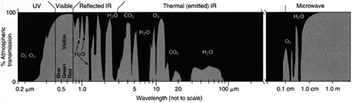
Figure 2. The atmospheric transmission windows for a variety of wavelengths. These are regions of the atmosphere where absorption is low, allowing the wavelengths to travel through the atmosphere with minimal attenuation [23].
Download figure:
Standard image High-resolution imageThe other main benefit of the SWIR band is the reduced risk to eye safety, as the human eye has significantly higher minimum permissible exposures (MPEs) for wavelengths greater than 1500 nm [24]. The main negative to the SWIR band is attenuation due to adverse weather and scattering, which is the most pronounced in the SWIR versus the other two atmospheric windows under discussion. We will briefly cover some experimental work and theoretical analysis of the attenuation that can be expected for SWIR wavelengths, followed by examples of successful missions that have used SWIR wavelengths in space. As the SWIR band is the only atmospheric transmission window with flight heritage, the later discussions on the MWIR and LWIR will only cover the experimental and theoretical results in laboratory conditions.
The European Space Agency has been investigating the appropriate wavelength to use for optical SatCom since at least 2010. The study (ESA Contract AO/1-5718/08/NL/US 'Feasibility Assessment of Optical Technologies and Techniques for Reliable High Capacity Feeder Links') has considered various usable wavelengths for FSO links between earth and satellites [25]. The oldest system successfully used is the 850 nm SWIR for the SILEX experiment [26], while recent interest has focused on the 1550 nm wavelength due to the availability of optical fiber components, high speed modulators capable of greater than gigabit speeds, and sensitive detectors approaching the quantum limit. While other SWIR wavelengths such as 1064 nm and 1300 nm have been used in the TESAT system, 1550 nm is still preferred due to the eye safety risks posed by wavelengths below the 1500 nm cut off where the eye no longer focuses infrared light [27]. This allows much higher 1550 nm laser powers to be used versus shorter SWIR wavelengths. The 1550 nm wavelength is already highly utilized with on-off keying (OOK) modulation and direct detection for fiber communication and can transfer well to SatCom. It is possible to achieve data rates as high as 10 Gbps with dense wavelength division multiplexing using 1550 nm laser [28]. The main issue for all wavelengths below 10 µm is aerosol scattering due to weather such as fog and haze [29]. This can be partially offset due to the compatibility of the 1550 nm wavelength with EDFAs, which allow for multi-watt output powers to increase the overall link margin. It is also possible to use more complicated modulation schemes such as phase shift keying (PSK) and hybrid schemes to increase data rates and efficiency [30]. One important risk factor that must be mentioned is that EDFAs degrade in space due to gamma rays, which induce color centers in the Erbium doped fibers. This increases absorption at both the pump wavelength and the amplified output wavelength and thus reduces the effective gain over time [31].
There have been a number of studies on the expected atmospheric attenuation due to scattering, atmospheric turbulence, and cloud cover using SWIR wavelengths [32–38]. Various weather conditions are typically categorized using a visibility value, which ties back to the Kruse + Kim model mentioned previously. Table 1 illustrates one possible classification for matching weather conditions with visibility values, although there may be some variance in these values depending on the consulted source.
Table 1. A classification of various aerosol-based weather affects according to their respective visibility values in meters [37].
| Weather condition | Visibility range (m) |
|---|---|
| Thick fog | 200 |
| Moderate fog | 500 |
| Light fog | 770–1000 |
| Thin fog/heavy rain (25 mm h−1) | 1900–2000 |
| Haze/medium rain (12.5 mm h−1) | 2800–40 000 |
| Clear/drizzle (0.25 mm h−1) | 18 000–20 000 |
| Very clear | 23 000–50 000 |
Of course, there are multiple types of fog and aerosol-based weather that can act as channel impairments, and some types of fog have a strong wavelength dependence while others are mostly unaffected by wavelength, as illustrated in figures 3 and 4.
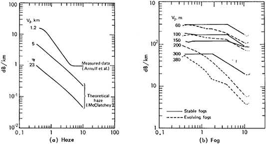
Figure 3. Attenuation versus wavelength for haze and fog at multiple visibilities. We can see that in general, attenuation is lowest for wavelengths near 10 µm, and the trend is longer wavelengths experience lower attenuation overall. Reproduced with permission from [35].
Download figure:
Standard image High-resolution image
Figure 4. Effective fog density (a measure of attenuation, lower density means less attenuation) as a function of wavelength, showing that the MWIR and LWIR bands perform significantly better in fog versus the SWIR. Reproduced with permission from [34]. © 1957 Optical Society of America.
Download figure:
Standard image High-resolution imageWhile aerosol-based weather affects SWIR wavelengths heavily, other weather such as rain appears to affect all of the atmospheric transmission windows equally, with the main factors determining attenuation being the rainfall rate, demonstrated in figure 5.

Figure 5. The calculated extinction coefficient for rain is compared to measured experimental data for the SWIR region. The extinction is almost entirely dependent on rainfall rate instead of wavelength. Reproduced with permission from [35].
Download figure:
Standard image High-resolution imageUnfortunately, attenuation due to clouds has been shown to be mostly wavelength independent. While there is a small benefit to be observed when utilizing 10 µm or above for FSO links, the cloud attenuation coefficients range from 10 to 100  depending on the type of cloud. This corresponds to attenuation values of 50–440 dB km−1, respectively, making FSO links extremely difficult to impossible when clouds are present over the ground station. The extinction coefficient for clouds as a function of wavelength is presented in figure 6.

Figure 6. The extinction coefficient for different types of clouds as a function of wavelength. While for some types of clouds, there is a significant dip in attenuation at 10 µm, the attenuation is still significant. Reproduced with permission from [35].
Download figure:
Standard image High-resolution imageThe only reasonable mitigation technique for cloud cover reported so far is to increase the number of ground stations to ensure that at any given point, it is statistically unlikely that all available ground stations have cloud cover that would cut the link availability. This has already been examined in a Canadian context by Gagnon et al where the availability of a single ground station in Canada can be expected to be available roughly 30% of the time, with that availability increasing to 93% for eight ground stations [39]. As a result, we can see that there are small gains in availability that could be realized by moving from the SWIR to longer wavelengths, but the main issue to overcome is cloud cover, which cannot easily be solved by switching to a longer transmission wavelength.
To conclude the discussion on the SWIR band, we will review several successful satellite missions that utilized SWIR light. These can serve as a useful case study of what has already been attempted in the field of SWIR SatCom, as well as provide a source of components that have flight heritage. In 1991, the SILEX optical interorbit experiment used an AlGaAs laser diode at 830 nm emitting at 60 mW to establish a 50 Mbps intersatellite link through direct detection [40]. In 1996 the GOLD experiment between the ETS-VI Satellite and Table Mountain Facility demonstrated a ground-to-satellite link using a GaAs laser at 830 nm emitting at 13 W to establish a 1.024 Mbps link. In 2009 the Deep Space Optical Link Communications Experiment used a Master oscillator power amplifier at 1058 nm at 1 W to establish an up to 20 Mbps link for inter-satellite/deep space missions [41]. In 2007, the Japanese KIODO mission used an AlGaAs laser at 810/847 nm to establish a 50 Mbps link from satellite-to-ground [42]. In 1989, the ETS-VI satellite was announced, which would go on to use an AlGaAs laser for the optical downlink at 830 nm at 13.8 mW, establishing a 1.024 Mbps bi-directional ground-to-satellite link, coupled to an Argon uplink laser at 532 nm [43]. In 2007, the Japanese Optical inter-orbit communications engineering test satellite used a laser diode at 819 nm emitting 200 mW to establish a 2.048 Mbps bi-directional inter-orbit link [44]. In 1994, the SOLACOS mission was designed to use a DPSS Nd:YAG laser at 1064 nm emitting at 1 W to establish a 650 Mbps GEO to GEO link [45]. In 2010, the short range optical intersatellite link was proposed by the ESA to use a DPSS Nd:YAG laser at 1064 nm emitting at 5 W to establish a 1–30 Mbps link for deep space missions [2]. In 2014 the NASA OPALS was able to achieve a 1.5 µm, 2.5 W, 50 Mbps link from the ISS to a telescope at a NASA ground station. More recently, the JAXA demonstrated on the SOLISS succeeded in a 1.5 µm bidirectional link from the ISS to a ground station, sending HD images over the system. The main factor in almost all cases limiting performance of the link is weather, and otherwise 1550 nm lasers would be an excellent candidate for optical SatCom [2, 27, 46–53].
2.3. MWIR—3–5µm
The MWIR is another atmospheric transmission window that is being considered for optical SatCom. Spanning the wavelength range of 3–5 µm, the MWIR band has attracted interest for both its atmospheric transmission properties as well as it is applications to spectroscopy, as several gases such as CO2 and methane have absorption lines in the MWIR. A MWIR specific absorption spectrum is illustrated in figure 7, pointing out the regions of absorption for water, ozone, and carbon dioxide.

Figure 7. The atmospheric transmission spectrum for the MWIR. While transmission across the spectrum is generally high, it is important to avoid the regions of strong absorption due to water, ozone, and carbon dioxide. Reproduced from [54]. CC BY 4.0.
Download figure:
Standard image High-resolution imageWhile MWIR sources and detectors are covered in more detail in sections 3 and 4, commercial availability of MWIR components lies between the SWIR and LWIR. In general, MWIR components are more expensive than their SWIR counterparts, and the variety of components is more limited. However, MWIR components are more developed than comparable LWIR components, and tend to be cheaper as well. This places the MWIR as a nice middle-ground between the SWIR and LWIR, both in terms of cost and free space transmission performance. It is important to point out that a MWIR link has not been demonstrated in space to the best of our knowledge, and so the following experimental results will focus on successful links in laboratory settings. In many cases, the link power and speed are discussed, but not the performance of the link with simulated atmospheric conditions. As a result, it is clear that more research needs to be performed on the atmospheric attenuation of MWIR sources. One of the 1st mid-infrared links was achieved by Martini et al using a quantum cascade laser (QCL) to establish a free-space television link over 70 m [55]. In 2008, Ip et al demonstrated the 1st MWIR link using nonlinear parametric frequency conversion at 3.8 µm with a speed of 2.488 Gbps using a non-return to zero quadrature PSK output [56]. In 2010, Soibel et al demonstrated a 70 Mbps link with a bit error rate less than  over a 1 m link in laboratory conditions. This link was compared to a 1550 nm link over the same distance through both clear weather conditions and simulated fog conditions. The attenuation over the 1 m link was measured and plotted in figure 8. It is clear that the mid-infrared link outperforms the SWIR link in every test case, with some MWIR links suffering less than half the attenuation of the SWIR.

Figure 8. The attenuation of the SWIR and MWIR links in the 1 m channel for two different types of fog. Reproduced with permission from [57]. © (2010) Society of Photo-Optical Instrumentation Engineers (SPIE).
Download figure:
Standard image High-resolution imageIn 2008, Tabirian et al analyzed the atmospheric propagation of MWIR light at 3.89 µm using holmium-based lasers and investigated how the atmospheric turbulence and scattering would change compared to the SWIR wavelength. In figure 9 we can see the sea level atmospheric attenuation coefficient for several wavelengths across several simulated atmospheres.
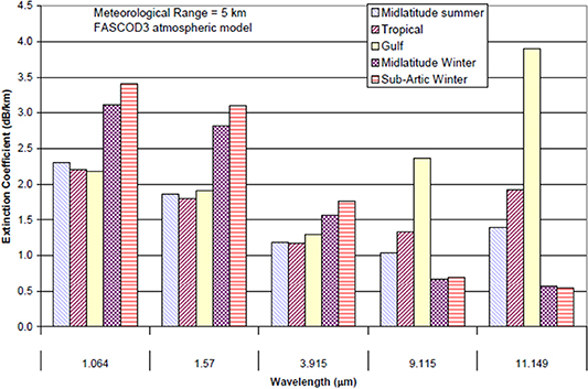
Figure 9. Sea-level atmospheric extinction coefficient for five model atmospheres and five model wavelengths. Reproduced with permission from [58]. © (2008) Society of Photo-Optical Instrumentation Engineers (SPIE).
Download figure:
Standard image High-resolution imageAdditionally, the mean signal to noise ratio was calculated for a SWIR and MWIR link using the Rytov variance in order to generate an estimated bit error rate versus mean signal to noise ratio in figure 10, where it can be seen that the MWIR link requires an SNR ∼25% lower than the SWIR to achieve a bit error rate of 10−8, demonstrating superior transmission through turbulence.
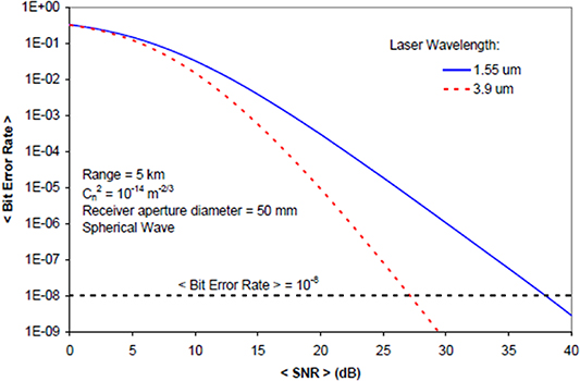
Figure 10. The variation in mean bit error rate with the mean SNR for a SWIR and LWIR link, assuming OOK with direct detection. We can see that the mean SNR required for a give bit error rate is lower due to the smaller likelihood of the MWIR link fading. Reproduced with permission from [58]. © (2008) Society of Photo-Optical Instrumentation Engineers (SPIE).
Download figure:
Standard image High-resolution imageIn 2017, Hao et al reported a nonlinear optics (NLO) based transmitter and receiver that generated 9.3 mW of 3.6 µm power, which was then turned into 12  W of 1550 nm power to be detected at the receiver [59]. In 2017 Pang et al developed a gigabit free space transmitter operating at room temperature using a QCL and forward error correction (FEC) [60]. In 2015, Luzhansky et al compared the use of pulse position modulation (PPM) with MWIR and LWIR QCLs in simulated atmospheric conditions using custom phase plates [61]. In 2018, Su et al developed a NLO based transmitter and receiver capable of 10 Gbps differential PSK (DPSK) transmission over free space with 3.4 mW of output power [62]. This concludes the review of the field of MWIR links; while there are other reported results, the selected papers are meant to be broadly representative of the current state of the field and act as important benchmarks to compare future links to. The general conclusion to draw is that the MWIR has undeniably better performance in weather such as haze and fog over the SWIR, with commercially available direct detectors and a wide variety of optical sources available. However, the limiting factor is on the detector side, where detectors are not as sensitive or high-speed as commercially available SWIR detectors. This is explored in more detail in section 4.
2.4. LWIR—8–12 µm
The LWIR band is the longest of the three wavelength bands under consideration, and likely the least developed from a commercial standpoint. It offers the best overall performance in adverse weather and atmospheric turbulence, easily beating the SWIR and MWIR bands. It is attractive for free space communication due to the minimal atmospheric attenuation, as well as promising applications in spectroscopy and all weather LIDAR. A LWIR specific transmission spectrum is shown in figure 11, showing that outside of specific gas absorption lines, the transmission is high.
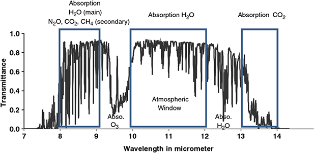
Figure 11. The MWIR atmospheric transmission spectrum, outlining important absorption lines for several gases present in the atmosphere. Reprinted by permission from Springer Nature Customer Service Centre GmbH: Springer Nature, Journal of Earth System Science [63], © 2011, Indian Academy of Sciences.
Download figure:
Standard image High-resolution imageAs covered in the introduction, atmospheric scattering and scintillation are reduced at longer wavelengths, so it is clear to see why the LWIR offers the best potential performance of all of the laser links under consideration. A LWIR link would likely have the highest mean received power and lowest power variance at the receiver, greatly reducing the required dynamic range and sensitivity of a detector for optical SatCom. We will now investigate reported free space links making use of LWIR wavelengths and comparing their transmission to SWIR wavelengths. As with the MWIR, to the best of our knowledge there have been no LWIR SatCom missions with LWIR payloads, and so the results will be limited to laboratory conditions. In 2008, Corrigan et al compared an 8.1 µm QCL to a traditional 1.55 µm telecoms laser source in both a fog event and rainfall event and compared the results to the Kruse + Kim model in the introduction over a 550 nm path in New York [64]. The recorded loss in dB km−1 is presented in figure 12 as a function of time, with several visibilities marked on the plot:

Figure 12. Transmission losses for several wavelengths in the presence of fog. It is clear that the loss at the LWIR wavelength is significantly reduced versus the SWIR band source, especially at low visibilities. Reproduced with permission from [64].
Download figure:
Standard image High-resolution imageIn 2021, Pirotta et al demonstrated modulation speeds of up to 1.5 GHz for LWIR free space beams at room temperature [65]. In 2001, Paiella et al demonstrated high frequency modulation up to 10 GHz of several 8 µm QCLs [66]. In 2019, Hinkov et al demonstrated high frequency modulation of ring and ridge QCLs at low GHz frequencies [67]. In 2016, Hinkov et al achieved a modulation frequency of up to 23.5 GHz in DFB QCLs [68]. In 2017, Mottaghizadeh et al reported 26.5 GHz modulation speeds for a buried heterostructure QCL using an ultrafast 65 GHz QWIP detector [69]. In 2019, Liu et al performed a comprehensive study and comparison of a 10.6 µm QCL FSO system to a 1.55 µm telecoms communication system using commercial off the shelf components that were further modified to facilitate high speed communication. They also successfully created a link emulator model and beam propagation tool, and performed a detailed analysis of how LWIR light propagates through atmosphere. Figure 13 illustrates their results with a comparison between the SWIR and LWIR sources.
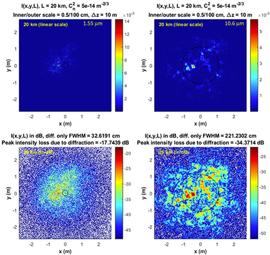
Figure 13. Simulated beam intensity at the receiver in linear (top row) and decibel (bottom row) units at 20 km range for 1.55 (left column) and 10.6 µm (right column) for a four inch diameter transmitter and receiver aperture. The solid lines show the beam size at the receiver for diffraction only. Reproduced with permission from [70]. © (2019) Copyright, 2019, General Technical Services, LLC.
Download figure:
Standard image High-resolution imageWe can see from the simulated results that a much larger portion of the incident beam ends up hitting the receiver compared to the 1.55 µm link, and so we can safely assume that the mean power would be much higher and the variance of the power at the receiver much lower for the LWIR link over the SWIR link. These experimental results presented are by no means the only experiments that have been reported in the LWIR band, but they are meant to be illustrative examples that serve as useful benchmarks of the state of the art for LWIR communication. The LWIR has clearly demonstrated the lowest attenuation due to weather of the three transmission windows, which is a benefit for SatCom. However, it also suffers the largest loss in telescope efficiency, and is the most difficult band to find high sensitivity detectors that are commercially available. As a result, it is likely that the LWIR band will need more development to occur on detectors and sources before it is commercially viable.
2.5. Conclusion
After reviewing the three atmospheric transmission windows, in an ideal case, the LWIR would be the optimal wavelength band to use for near earth free space communications. The theoretical and experimental models show that the atmospheric scattering and turbulence effects are significantly reduced in the LWIR. The main obstacle in adopting the LWIR is the availability of suitable sources and detectors, covered in more detail in sections 3 and 4. While LWIR sources are approaching the point where watt-level, stable, room temperature power is achievable, LWIR detectors are significantly slower and less sensitive than commercially available SWIR detectors. This makes it difficult to recommend that the LWIR should be selected for missions in the next 5 years for optical SatCom. However, given the large interest for both military and civilian applications of LWIR technology, it is not out of the question that LWIR sources and detectors will advance rapidly in the next 10–15 years, and they will be the future of near earth optical satcom once sources and detectors in the LWIR range are as well-developed as the current SWIR sources and detectors. A possible middle ground between the SWIR and LWIR performance is the MWIR band, which offers moderately improved performance in terms of atmospheric turbulence and scattering, while having sources and detectors that are more developed than the LWIR sources and detectors. While the MWIR sources and detectors are still slower and less sensitive than the LWIR detectors, they do offer improved performance over the LWIR, and are closer to being realized in practical optical SatCom applications. It is reasonable to assume that we will see the first practical implementation of a MWIR SatCom link in the next 5–10 years.
Despite the advantages of the MWIR and LWIR when considering atmospheric effects, it is difficult for either to compete with the maturity and cost of components operating in the SWIR band. It is also the least risky option to develop, as NASA, JAXA, and the ESA have all demonstrated SWIR based optical links from low Earth orbit and the Moon (∼400 000 km). As such, it is easy to recommend the SWIR band as the backbone for optical SatCom in the next 5–10 years, especially for intersatellite links where atmospheric effects are nonexistent. The only question that remains to be answered is whether the SWIR band would be suitable for a globally connected constellation of low Earth orbit satellites. If an all-weather network is desired, it will be mandatory to utilize multiple ground stations to mitigate outages from poor cloud cover or poor weather. To ensure high speed performance across the network, these ground stations would likely be connected via optical fiber networks or terrestrial FSO links. While the SWIR will likely be dominant in the near future, the MWIR and LWIR bands offer significant performance increases over the SWIR band in poor weather. As a result, moving to longer wavelengths will benefit scenarios where a ground station has poor weather for the SWIR band such as heavy haze or fog, and in situations with heavy cloud cover, it will be necessary to use a different ground station. In conclusion, there is a clear benefit in moving to the MWIR and LWIR so long as the technology is present to support this transition in the next decade or so.
3. Laser sources
The laser source is responsible for emitting a tightly focused beam of light, upon which information can be encoded via modulation to enable greater than gigabit per second speeds. The laser used sets several factors that determine the link budget available for a given ground station. This section of the review focuses on the lasers themselves, including important metrics such as wavelength, optical power, efficiency, and modulation capabilities. In general, a laser with high optical output power, high efficiency, and a large modulation bandwidth is desirable for SatCom, as we established in the introduction. We will cover the state-of-the-art for several laser archetypes that range from mature lasers with flight heritage to promising up-and-coming laser sources that are being considered as the 'future' of SatCom. We will discuss several types of laser sources that could be used as part of an optical SatCom transmitter. First, we will look at the general design of transmitter and briefly discuss what requirements a laser source should meet in order to be employed for optical SatCom. A generalized optical SatCom terminal is illustrated in figure 14, including the necessary telescope for beam focusing.
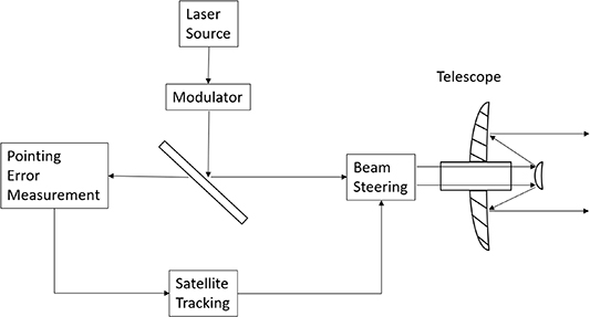
Figure 14. A typical laser transmitter block diagram for satellite optical communication.
Download figure:
Standard image High-resolution imageFigure 14 illustrates the laser source and modulator coupled into the beam steering system and focusing telescope via a dichroic mirror. The dichroic mirror is typically reflective at the transmitting laser wavelength and transparent for other wavelengths. A detector of some kind images the satellite and external circuitry calculates the pointing error, which is fed to a tracking system to orient the satellite or ground station satellite to minimize pointing errors. The transmitter in figure 14 may or may not have an additional external amplifier and external modulator for the laser, depending on the modulation scheme and optical power required. If a laser source can be directly modulated at high speeds (i.e. modulating the current injected into the diode at high speed), then an external modulator may not be necessary. In a similar vein, if the output power of the laser is sufficiently high, an external optical amplifier such as an EDFA will not be necessary. Of course, this raises the question of what suitable output power and modulation speed for an optical SatCom mission is. In 2014, Gagnon et al performed a review of satellite developments for laser communication in a Canadian context. Their recommendations for a low earth orbit satellite were a payload mass of 50 kg, power consumption for operation and standby mode of 100 W and 40 W, respectively, a data rate of at least 1 Gbps, a communication transmit power of 2 W optical, a modulation format of either PPM or binary phase-shift keying, using a telescope with a diameter of ∼12.5 cm [39]. These will be the parameters we assume the laser sources must meet or exceed to be suitable for SatCom from LEO to ground.
3.1. Semiconductor lasers
Semiconductor lasers, sometimes referred to more broadly as laser diodes, are one of the most common laser types found in day-to-day life, industrial applications, and research and development. This will not be an exhaustive review of the operating principles of semiconductor lasers, as it is assumed the reader has basic knowledge of the operating principles of lasers. For those seeking a detailed reference text where common laser relations are derived, 'Lasers' by Siegman or 'Principles of Lasers' by Svelto are excellent texts suitable for advanced undergraduate or graduate student self-study [71, 72]. Instead, due to the broad nature of semiconductor lasers as a topic, we will focus on the SWIR band (800–1700 nm) specifically due to its current use and relevancy to optical SatCom. Finally, we will cover upcoming antimonide lasers which have the potential to provide compact lasers sources in the 3–3.5 µm MWIR range. As a side note, while QCLs are technically semiconductor lasers as they are fabricated from semiconductor materials, their operating principles and capabilities are unique enough that they have been given their own section.
A common semiconductor laser structure available commercial is a DFB. By adding a periodic grating element to the active medium of the laser, the properties of the output spectrum such as linewidth are improved significantly. This grating structure is illustrated in figure 15.

Figure 15. A sample DFB laser design. The grating in the body of the laser acts as a wavelength-selective element, narrowing the linewidth of the laser output. Reproduced from [73]. CC BY 4.0.
Download figure:
Standard image High-resolution imageThrough careful design of the period of the resonator, a single mode can be selected for lasing by minimizing the loss at this mode and increasing the loss significantly for other modes. This means the DFB lasers can guarantee single-mode operation over a relatively large wavelength tuning range of up to several nanometers [74]. The grating could also be part of an integrated waveguide structure if desired. DFB lasers can be acquired over a wide range of output wavelengths and are a mainstay in the telecommunications industry due to their excellent wavelength selectivity. Typical output power is in the tens of milliwatts, although this can be supplemented via amplifiers such as EDFAs at SWIR telecoms wavelengths. It is possible to obtain tens of Gbps modulation speeds using DFB lasers [75].
Another common architecture is the vertical cavity surface emitting laser (VCSEL), which obtain single mode operation by placing the active region between two highly reflective cavity mirrors (R > 99.5%). These are typically highly selective Bragg mirrors placed on both ends of the active region during the fabrication process. They achieve a similar result to DFB lasers, but are typically more compact, and the vertical structure allows many VCSELs to be fabricated on a single wafer, driving down fabrication costs. VCSELs have been targeted for optical SatCom applications in the last decade due to their narrow linewidths, fast modulation speeds (up to 25 Gbps), and low current densities and power consumption. Additionally, their low output power can be compensated for by creating arrays of VCSELs, allowing for modular transmitter designs depending on power and space requirements. Several studies have successfully demonstrated the potential for VCSELs to succeed in intersatellite applications, although even taking into account the possibility for arrays, it may be difficult to obtain Watt-level powers that would be desirable for satellite-to-ground links. NASA has also developed a patent-pending system for using VCSELs for highly accurate fine satellite pointing with nanosecond response times [76–79].
To conclude this section on semiconductor lasers, we will summarize the advantages, disadvantages, and general risks associated with such lasers. Semiconductor lasers have the significant advantage of flight heritage on past optical SatCom missions and payloads at gigabit speeds over the mission lifetime, as covered in section 2.2. As a result, there is actual link data associated with the SWIR for SatCom that simply does not currently exist for MWIR and LWIR links, which have been limited to terrestrial links so far. Additionally, the maturity of semiconductor lasers offers low cost and high performance compared to more novel technologies such as QCLs and NLO-based lasers. Their high efficiency and compact size mean that they can be integrated into small, lightweight satellite payloads relatively easily, and they have demonstrated capabilities >25 Gbps modulation speeds thanks to their long history in the telecommunication sector. A typical drive voltage of ∼2 V and current of ∼100 mA is typical for a low power laser diode, reaching up to 10 V and 10 A for high power diodes, meaning that there is a wide range of diodes to select based off electrical power requirements for the mission. Semiconductor laser diodes also benefit from long lifetimes, ranging from 20–40 years on average. The main disadvantage of semiconductor lasers within the context of this review is that, currently, laser diodes with an emission wavelength outside of the 0.4–2.5 µm range are difficult to find. In the MWIR there are antimonide-based lasers, but these should still be considered in the early research stages, and it will be some time before they are commercially available. Examples of semiconductor lasers in the LWIR are difficult to find at all, and to the best of our knowledge no promising options exist. Additionally, the environmental temperature can affect the efficiency of the semiconductor laser and cause the emission wavelength to drift significantly, and in extreme temperatures there may be permanent damage and premature failure to operate. This will increase payload complexity as special care must be taken to ensure the laser's temperature is kept as stable as possible in orbit. Overall, semiconductor lasers remain a promising solution for optical SatCom, despite their drawbacks.
3.2. Quantum cascade lasers (QCLs)
QCLs are a type of laser invented in 1994 by J Faist, F Capasso, and others that operate in a markedly different manner than most semiconductor-based lasers [80]. In a typical semiconductor laser, electron transitions between the conduction and valence bands produce photons with energy equal to the band gap separating the two bands. This is known as an interband transition, as the electron transitions between two different bands in the semiconductor. In a QCL, repeating thin (nanometer scale) layers of semiconductor material are sandwiched together to form multiple quantum wells, creating sub-bands within the conduction band where the transition and photon emission takes place. The difference between interband and intersubband transitions are illustrated in figure 16.
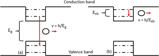
Figure 16. Demonstrating the difference between interband (a) and intersubband (b) transitions that produce photons in semiconductor materials.
Download figure:
Standard image High-resolution imageThe novelty of QCLs comes from their unique multiple quantum well design. A single electron can undergo a photon emitting transition, and then tunnel into a new active region to emit another photon, and so on for each active region. This enables high quantum efficiencies, as one electron can be responsible for tens of photons being emitted. Due to the sandwiched quantum well structure of QCLs, it is possible to engineer a near continuous emission spectrum within the conduction band that is decoupled from the bandgap dependence of traditional semiconductor lasers. As a result, QCLs are capable of emitting over a wide wavelength range of ∼2.6–250 µm [81]. This is one of the main benefits of QCLs, as it is currently one of the only lasers capable of emitting in the 3–5 µm (MWIR) and 8–10 µm (LWIR) atmospheric transmission windows with high optical power. State of the art QCLs are capable of room temperature continuous wave (CW) output powers of up to ∼5 Watts at room temperature in the 3–5 µm range, with efficiencies approaching 31% [82]. However, there is typically a trade-off in optical power versus the operating temperature of the device. When operating at liquid nitrogen temperature, for example, it is possible to obtain wall-plug efficiencies that approach 45%, with the expected wall plug efficiency (WPE) dropping as operating temperature rises; the wide temperature swings in a space-like environment may prove to be detrimental to stable QCL operation in space.
There is excellent potential for using QCLs in ground-based FSO communications. Multi-watt level output powers in both the MWIR and LWIR wavelength bands have been demonstrated with >10% WPE [83–86], which is a low efficiency for satellite applications but useable for ground stations given the higher availability of electrical power. Additionally, QCLs have high theoretical modulation bandwidths (>100 GHz) in the MWIR and LWIR bands, due to the lifetime of the upper state being in the picosecond range, although practical demonstrations have only achieved a fraction of this theoretical limit so far [87]. A challenge in recent years has been direct modulation of QCLs at high bandwidths. Current experiments have demonstrated bandwidths up to 26 GHz for direct modulation, but only at temperatures between 77 K and 250 K [68, 88]. Additionally, many of the reported high speed QCLs are operating at low output powers in the 10–100 mW range, and the power efficiency is often unreported, making it difficult to decide if direct modulation is a viable option for SatCom due to power constraints. There is future work involving the measurement of modulation depth, spectral purity, and QCL chirp that must be reported before an informed decision can be made for direct modulation of QCLs in space [87]. As a potential alternative to direct modulation, a number of experiments have been carried out for external modulators as well. This includes electro-absorption modulators, modulation of the complex refractive index, graphene metal plasmons, or lithium niobate waveguides [89–93]. However, so far none of these have offered clear cut solutions that can be brought to market quickly.
To conclude this section on QCLs, we will summarize the advantages, disadvantages, and general risks associated with such lasers. One of the advantages of QCLs is their widely tunable spectral range of 3–250 µm, which can easily cover the MWIR and LWIR bands. The short upper-level lifetime of cascade lasers also allows for theoretically >100 Gbps modulation bandwidths, with practical bandwidths >3 Gbps having been demonstrated. The output linewidth of QCLs is also narrow when compared to other semiconductor lasers, allowing optical filtering at the receiving telescope to better target the transmission wavelength without significant losses. QCLs also carry significant disadvantages. While room temperature QCLs have been demonstrated, their efficiencies tend to be limited to the 10%–20% range, at which point fiber lasers (discussed in the following section) can offer higher efficiencies that are more attractive on satellites with limited power available. The trade-off then becomes whether SWIR fiber lasers with higher efficiency are preferred to QCLs with superior MWIR and LWIR wavelengths, due to the lack of MWIR and LWIR fiber lasers. Cooled QCLs are not feasible for satellite applications due to the difficulty of active cooling in space. Finally, the lack of effective external modulators in the MWIR and LWIR mean that cascade lasers and other MWIR and LWIR sources are limited to direct detection for the time being, restricting potentially more efficient modulation formats. Despite these setbacks, QCLs are a promising option for ground-based FSO communication and in the next 10–20 years look to be approaching the point where they can be considered for satellite-based communication as well. The technology has advanced rapidly since it is conception in 1994, and it is still an active area of research that is progressing quickly.
3.3. Fiber lasers
Fiber lasers are unique over the other lasers presented in this review, as the light generation takes place entirely inside of an optical fiber, which is a flexible transparent piece of material (typically silica) covered with a cladding material that confines the light through total internal reflection. In this approach to lasing, the gain medium is typically a dopant within the optical fiber itself, with common choices being ytterbium or erbium. The dopant is then optically pumped via a laser diode, or in some cases another fiber laser, to generate lasing action in the doped fiber core. These lasers can be found in both FSO setups as well as fiber-only setups, where all the necessary components are fiber-coupled together. The pump diode can consist of a single diode, multiple diodes, or arrays of diodes coupled into the fiber via a fiber combiner. The cavity mirror in fiber mirrors is typically a Bragg grating at either end of the optical fiber, providing a high degree of wavelength selectivity for the reflected wavelength if required. The total internal reflection allows fiber lasers to be bent and coiled with minimal difficulty, and the lack of external optics to align mean that fiber lasers can be used in situations where bulk optics would be expensive and time-consuming. Fibers can be made longer to increase the interaction length and the potential gain, and the high surface area to volume ratio of optical fibers makes heat dissipation less of a concern than for other laser configurations [94].
Fiber lasers are capable of handling outputs up to multiple kilowatts of optical power. However, the small diameter of the fiber guarantees that the intensity of light inside the fiber is high. As a result, output much higher than the multi-kilowatt range could lead to nonlinear effects dominating and lowering the efficiency, or in extreme cases, damage to the optical fiber. If single mode operation is not necessary, it is possible to increase output power to the hundreds of kilowatts. Due to this scalability for output power, fiber lasers are quite versatile. They can be used for component welding or laser cutting with ultrafast pulses, or the stimulated emission can be suppressed, and the spontaneous emission is allowed to lase, such as in Raman fiber lasers. The most likely configuration, however, is a single mode silica glass with a rare earth doped core. The most common dopants mentioned earlier are ytterbium and erbium. Erbium doped fiber emits between 1530 and 1620 nm typically and is commonly used in telecommunications alongside EDFAs due to the low loss in optical fibers at these wavelengths, where they are capable of multi-watt output powers [95]. Another common dopant is thulium which is capable of emitting in the 1800–2050 nm range. Thulium lasers have mainly found use in biomedical applications, as it covers a large absorption band in liquid water [96]. A more recent addition to the range of dopants is Holmium, which is capable of extending the emission spectrum of fiber lasers into the 1.9–2.2 µm band. Holmium fiber lasers have been investigated in the past for FSO communication, as the potential for high output powers and fast modulation speeds at longer wavelengths is promising due to the potential for atmospheric effect mitigation in the free space channel [97]. Finding single dopant solutions to provide fiber lasers past the 2.2 µm range has been difficult. One potential option is dysprosium, which has recently had some success in providing a 3 µm output with a 1700 nm input pump inside of a ZBLAN fiber [98]. There has also been some level of success in using dual-wavelength pumping to produce mid-infrared fiber lasers with hundreds of milliwatts of output power using two concurrent pump sources [99].
Fiber lasers have attracted some attention for satellite optical communication, due to their flexibility enabling a more diverse design space over more traditional FSO solutions. The core and cladding ensure the light propagating in the fiber is well-shielded from the environment (such as dust), and the ability for the fiber to be bent and coiled to a degree ensures that fiber laser setups can be built in a rugged fashion, so long as the entire solution is fiber based. While the majority of past satellite missions mentioned in section 3.1 use semiconductor lasers, there has been increasing interest in utilizing the 1550 nm wavelength for FSO communications, both intersatellite and satellite-to-ground. This is largely due to advancements in fiber optic communication, leading to commercial availability of high quality, off the shelf optical and electronic parts. The consensus seems to be that fiber lasers would be ideal for inter-SatCom, as the 1550 nm wavelength has limited losses in the vacuum of space and can be modulated at tens of Gbps speeds. The main challenge for 1550 nm laser sources in space is the atmospheric transmission channel. It is generally agreed that while the 1550 nm wavelength lies in one of the atmospheric transmission windows, it is significantly attenuated by weather effects such as fog, rain, snow, and haze ranging from 30 to 300 dB km−1. This means that adoption of 1550 nm as a satellite-to-ground standard would involve other mitigation techniques, such as utilizing multiple ground stations to limit having all ground stations affected by negative weather events. The main factor in almost all cases limiting performance of the link is weather, and otherwise 1550 nm lasers would be an excellent candidate for optical SatCom [76–90].
To conclude this section on fiber lasers, we will summarize the advantages, disadvantages, and general risks associated with such lasers. Fiber lasers have a large advantage in their maturity, as several commercial options can be found with a variety of output characteristics. Additionally, the optical fibers allow for miniaturization and weight reduction, which can significantly reduce costs for satellite payloads. The lack of free-space components coupled with the overall flexibility and durability of optical fibers means that the need for complex and time-consuming optical alignment is greatly reduced. The fiber cladding also isolates the optics from the harsh external environment, and since the fiber can be coiled and bent the ruggedness of fiber-based designs are high. Fiber lasers also offer small volume-to-area ratios which aid heat mitigation efforts and increase potential efficiencies. There are some disadvantages to fiber lasers as well, with a major con being the difficulty of obtaining longer infrared wavelengths. While holmium and dysprosium doped fibers currently show promise in the MWIR range, they are still in the early research stage, and to date there are no notable examples of LWIR fiber laser emission. Another issue is the high optical intensities present in optical fibers due to their small diameters meaning unwanted NLO effects can be present and may require additional design work to compensate for. Finally, the low gain per unit length means that in some cases, tens of meters of optical fiber may be required to achieve the desired optical output power, which may be a problem in ultra-compact payloads. Finally, further research must be carried out on the effects of cosmic radiation on the lifetime of fiber components such as EDFAs, as there is evidence that radiation damage can lower device efficiency over the lifetime of the mission. Despite these disadvantages, fiber lasers are a very attractive option for optical SatCom and are a low-risk option due to successful flight demonstrations from NASA and JAXA, and there will certainly be future demonstrations utilizing fiber lasers as well. If successful MWIR and LWIR emitters can be developed with the same ruggedness and flexibility as SWIR fiber lasers, they would likely be positioned to gain a dominant position in the optical SatCom market.
3.4. NLO-based lasers
NLO is a unique approach compared to the other types of lasers covered in this review, in that it relies on taking existing lasers (solid state, diode, fiber, cascade, etc) and using nonlinear crystals to convert the output wavelengths of the original lasers into a new wavelength band. Instead of covering different laser types in this class of technology, we will cover the main type of frequency conversion that is relevant to optical satcom, and then cover the state of the art in NLO for FSO communication. This will conclude with a discussion of the advantages, disadvantages, and risks of NLO relative to other lasers. As this is not a review of NLO, we will be skipping some of the rigorous background derivations that would show where all the following relations come from. If interested, references to Boyd [100] and Powers [101] are included as introductory texts on the topic which provide derivations in great detail.
One important consideration for NLO is the nonlinear medium that will be used. While there are a variety of NLO crystals, such as KH2PO4 (KDP), LiB3O5 (LBO),  -BaB2O4 (BBO), KTiOPO4 (KTP), and LiNbO3 (LN), some are better suited to optical SatCom. KTP and LN are promising candidates for allowing communication in the 3–5 µm MWIR band, as they are two of the only nonlinear crystals with a transparency range that reaches from the visible (0.4 µm) to 4.5 µm (KTP) or 5 µm (LN). Additionally, these crystals have high nonlinear coefficients, which is a measure of the strength and thus efficiency of NLO processes in the crystal. To simplify, a higher nonlinear coefficient means that the wavelength conversion process will be more efficient. KTP has a nonlinear coefficient as high as 17.4 pm V−1, while LN can reach 27 pm V−1. While the previously mentioned materials are promising for MWIR generation, they are incapable of LWIR (8–14 µm) generation due to their transparency ranges. Nonlinear crystals such as AgGaS2 and ZnGeP2 have transparency ranging from the visible to above 10 µm, making them suitable for LWIR generation. AgGaS2 has a nonlinear coefficient of 12.5 pm V−1, while ZnGeP2 has a nonlinear coefficient of 75 pm V−1, meaning they are just as capable as their MWIR counterparts [102]. Another promising up-and-coming technology for LWIR generation is orientation-patterned semiconductors (OP-SCs). Common III–V semiconductors such as gallium arsenide (GaAs) and gallium phosphide (GaP) have transparency from the visible to 18 µm and significantly higher nonlinear coefficients than many nonlinear crystals, with coefficients of 45 pm V−1 for GaP and up to 100 pm V−1 for GaAs. However, the manufacturing process is far from perfected and still in the research and development phase, and so it is difficult to obtain high-quality OP-SC crystals for frequency conversion processes. Further development of this technology could lead to significant progress in affordable and compact LWIR laser sources for optical SatCom, however, and this is an active area of research [103–109].
One of the most fundamental NLO processes is difference frequency generation (DFG). This process consists of a pump laser of wavelength  and a signal laser with wavelength
  impinging on a NLO crystal with a 2nd order optical nonlinearity. The pump photons are then converted into one photon each of the signal wavelength as well as a 3rd wavelength known as the idler, where the idler photons have energy equal to the difference in energy between the pump and signal. Figure 17 below illustrates the process for a 2nd order nonlinear medium.

Figure 17. The DFG process. Typically, there is no input wave  and it is instead generated in the nonlinear crystal.
Download figure:
Standard image High-resolution imageFor this to happen efficiently, a phase matching condition must be maintained in the crystal to maximize momentum conservation. The phase matching term represents the difference in momentum between the three waves, and is often represented as:
where  is the wave number of the respective wave (3—pump, 1—signal, 2—idler) The most efficient wavelength conversion occurs when 'perfect phase matching' is maintained, which is when
  . Due to the refractive index dependence on wavelength, this condition rarely occurs naturally in nonlinear photonic crystals, and so there is some degree of phase mismatch, and the efficiency suffers. There are two main methods to resolve this issue, which include birefringent phase matching and quasi-phase matching. In birefringent phase matching, the three waves polarized such that each wave 'sees' a different refractive index in the crystal, allowing the phase mismatch to be very close to zero and enhancing the efficiency. In quasi-phase matching, the nonlinear crystal undergoes a periodic poling process that occasionally flips the domain of the nonlinear coefficient. While the derivation is left out for brevity's sake, the result of quasi-phase matching is an additional term in the phase matching equation:
where the final term is the additional momentum imparted by the poling of the crystal with period  , typically in microns. The crystal can be attached to a thermoelectric cooler to fine-tune the phase matching and bring the phase mismatch very close to zero.
The intended application for DFG in the context of SatCom is to use a telecoms band 1550 nm laser as one of the two input lasers, and then provide a 2nd pump laser at another wavelength such as 1064 nm. In this case, the DFG process will produce a photon with a wavelength of ∼3.4 µm, which falls into the MWIR atmospheric window. It is also theoretically possible to use a 1550 nm laser and the 1342 nm transition line of an Nd:YVO4 diode pumped solid state laser to produce photons of ∼10 µm wavelengths, so the same concept can be applied to produce laser sources in the LWIR window as well. The transmitter would work by modulating the 1550 nm diode, which is a wavelength that is easy to acquire at high powers thanks to its high degree of usage in the telecommunications industry and access to EDFAs capable of amplifying the 1550 nm light to watt-level powers. The only limit to the modulation speed is the limit of the 1550 nm laser itself, as NLO processes occur on a timescale so short relative to modulation speeds that they are effectively instantaneous [110]. Thus, compact MWIR laser sources capable of being modulated at high speeds are theoretically possible using DFG.
Nonlinear frequency conversion processes scale with the intensity of the input light, and so input waves must be tightly focused (beam diameter < 200 µm) and the optical power must be maintained at tens if not hundreds of watts. While this condition can be achieved via the use of an optical resonator (a DFG process inside of a laser resonator is sometimes referred to as an optical parametric oscillator or OPO) to keep electrical requirements low, and while the pump lasers can have optical efficiencies >30% [111, 112], there is an additional efficiency drop due to the fact that nonlinear frequency conversion is not 100% efficient. As a result, the combined efficiency of the nonlinear frequency based MWIR source may be lower than that of a single telecoms SWIR 1550 nm source. Additionally, the requirement for two input lasers increases system cost and complexity, as well as power requirements on the satellite. Another consideration is that NLO frequency conversion is temperature sensitive, and it is mandatory to include a thermoelectric cooler to keep the nonlinear crystal at the optimal frequency conversion temperature. This temperature can be selected through appropriate crystal design, and it is possible to decrease the temperature sensitivity of nonlinear crystals through 'chirping' of the period [113]. Nonetheless, the wide temperature ranges the crystal may be subjected to in space-like conditions must be accounted for during the satellite design stage, and as such may lead to increased payload complexity.
There have been several recent experiments covering the applications proposed here, specifically the generation and detection of MWIR light through DFG and SFG, respectively [59, 62, 114, 115]. A state-of-the-art transmitter laboratory setup is illustrated in figure 18.
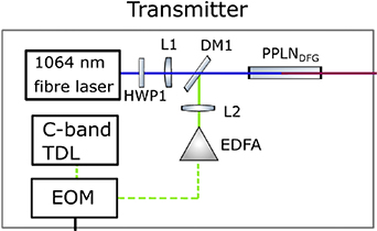
Figure 18. A state of the art single pass setup where a 1064 nm and 1550 nm laser are coupled into periodically poled lithium niobate (PPLN) to generate MWIR light. Reproduced from [115]. CC BY 4.0.
Download figure:
Standard image High-resolution imageThese methods have typically suffered from low output powers in the nanowatt to milliwatt range that would not be suitable for the link distances involved in SatCom. This can mainly be attributed to the use of single-pass device designs, where the two input waves are only allowed to pass through the nonlinear crystal once before producing the DFG or SFG output photons. One potential solution is to use compact intracavity designs, which hold the potential to greatly increase the input and output power of MWIR light available via the use of optical resonators [62, 116, 117]. It is also possible that further development could be achieved using waveguides for higher conversion efficiency and more compact device designs. To the best of our knowledge, such intracavity designs have not been attempted or reported in research yet for high speed MWIR communication and detection, and as such provides a promising avenue for research and development. In terms of the commercial market, there are no packaged sources that you may buy from industry that are designed for high-speed optical communication based on NLO. The commercial market has mainly focused on MWIR and LWIR generation via optical parametric oscillators. These are capable of higher output powers than QCLs, but typically at the cost of less spectral purity, modulation speed, compactness, and mechanical robustness due to the addition of a resonator design and the high degree of alignment required for spectroscopy purposes (the most common usage of OPOs) [87]. As a result, a direct market comparison will look unfavorable for NLO-based lasers, as the commercial market has not currently offered any products that fill this gap in the market.
In summary, NLO frequency conversion remains a promising candidate for creating MWIR and LWIR sources for optical SatCom. There are numerous advantages and disadvantages to this approach. A major advantage is that, outside of QCLs, NLO remains one of the most promising methods of generating MWIR and LWIR laser sources. There is also a large benefit to the proposed designs in that many of the components required can be acquired in the form of SWIR sources and detectors already available on the market, leveraging the maturity and high level of performance of the telecommunications sector equipment. Additionally, because of the near instantaneous timescale of NLO processes, the only limitation on the modulation speed for MWIR and LWIR sources will be the modulation speed of the input SWIR lasers. The main concerns with such systems as they are found in the market are the requirement of two lasers sources to produce one MWIR/LWIR source, increased size, lower power efficiency, low optical output powers, and increased optical alignment complexity. The efficiency problem is particularly difficult to solve, as there must be an additional loss of efficiency due to the added wavelength conversion step. Maximizing wavelength conversion efficiency will be necessary for NLO sources to remain attractive when compared to alternative lasers described previously. Fortunately, there is potential for simplification and miniaturization through the use of either intracavity designs or waveguides, both of which offer the potential for higher conversion efficiencies and higher optical output powers than the current state of the art. Another issue that must be considered in SatCom applications is that nonlinear conversion efficiency is heavily dependent on maintaining a stable temperature for the nonlinear crystal. This is usually accomplished with the addition of a Peltier element, but the extreme environment of space means that special attention must be placed on this requirement. Regardless, there is good reason to believe that with appropriate investment into R&D, it will be possible to produce more efficient and more compact MWIR and LWIR sources and detectors using NLO frequency conversion.
3.5. Modulation
In order to encode information onto the laser signals being transmitted, the laser must be modulated in order to represent the binary data being sent. In the context of SatCom, it is common to use intensity modulation and direct detection (IM/DD) schemes based on return-to-zero (RZ) and non-return-to-zero (NRZ) modulation formats [118]. The trade-off between RZ and NRZ methods are that RZ methods tend to be more power efficient but require twice the bandwidth for a target data rate versus NRZ. Commonly used formats are OOK, where the transmitter is turned on and off repeatedly to represent binary 0s and 1s respectively, and DPSK [119]. DPSK consists of modulating the phase of the transmitted signal relative to the previous signal and can be more power efficient than OOK due to the ability to send multiple bits per symbol. However, PSK schemes are particularly sensitive to the phase noise that accumulates in the transmitted signal over long distances, which is further exacerbated by atmospheric turbulence in the channel. This can be corrected at the receiver via adaptive optics, which corrects the incoming wavefront using fast steering mirrors and an optical feedback system [120]. This has the drawback of increasing the cost and complexity of the receiver. As a result, IM/DD schemes are common in SatCom due to their low cost and simplicity relative to other modulation formats. Some errors in the IM/DD link due to atmospheric losses can be corrected using FEC methods, which sends redundant data to allow for data to be recovered at the receiver even in the presence of significant noise [121]. Discussion of FEC and more complex coherent detection schemes are beyond the scope of this review, and we will instead focus on the availability of high-speed modulators for the SWIR, MWIR, and LWIR bands to facilitate a hypothetical gigabit NRZ-OOK communication link.
The most straightforward way to modulate an optical source is direct modulation. Direct modulation is a form of amplitude modulation where the input injection current to the laser is modulated. This is usually performed practically by maintaining a DC current and adding a smaller AC component to the current that varies with time. A simplified circuit level diagram of direct modulation is illustrated in figure 19.

Figure 19. Circuit schematic of direct modulation. The series resistance Rs protects the laser diode and maintains a fixed current, while  and
and  are the DC and AC current components, respectively.
Download figure:
Standard image High-resolution imageThe main benefit to direct modulation is that it is cheap and easy to implement when compared to commonly used electro-optic (EO) modulators, which will be covered shortly. Most semiconductor lasers have modulation frequency responses ranging from a few GHz up to tens of GHz, with parasitic capacitance from the diode junction structure and diode electrical contacts being a limiting factor. Direct modulation is viable across all three wavelength bands under consideration, and as mentioned in the QCL section, cascade lasers have theoretical modulation bandwidths up to hundreds of GHz. Another form of direct modulation is pulse modulation, which takes advantage of the short turn-on and turn-off times of semiconductor lasers. Direct modulation can produce sub-nanosecond pulses and can reach data rates higher than the pulse repetition rate by taking advantage of modulation formats allowing multiple bits per pulse to be transmitted, such as pulse-interval modulation [122]. Another possibility is to utilize the relaxation oscillations of the semiconductor laser to promote self pulsing, and then modulate the laser using PPM [123]. The main advantage of utilizing optical pulses over CW lasers is that the peak power of optical pulses can be on the order of kilowatts, compared to the typical watt-level power of CW lasers. This can increase the link budget by several orders of magnitude, increasing link availability and reducing downtime for optical links.
The other main alternative for optical modulation is using EO modulators as an external modulator for the laser. In this case, the laser is typically held constant in CW mode and the light passes through an external component where modulation is performed. There are two main types of EO modulators, refractive and absorptive, depending on whether the real part or imaginary part of the refractive index is modified, respectively. A discussion on how refractive and absorptive modulators differ and the theory behind them is beyond the scope of the review, but interested readers can find excellent resources on the Kramers–Kronig relations and how this behavior is derived [124]. The main operating principle of EO modulators is that many materials experience a change in refractive index when an electric field is applied to the material. The most common effect utilized in commercial modulators is Pockel's effect, which is a linear effect governing how the refractive index changes with the electric field. Another effect used in EO modulators is the Franz-Keldysh effect, which modifies the absorption of the EO crystal [125]. There is the nonlinear Kerr effect as well, but this is not typical seen outside of pulsed applications due to the high intensities required to observe NLO phenomena. There are a number of common materials used for EO modulators including GaAs, GaP, LiNbO3, LiTaO3, and quartz, which have large Pockel's coefficients and can be integrated into bulk and waveguide designs relatively easily [126–128]. Outside of amplitude modulation, EO modulators can also be used for phase and polarization modulation, typically by taking advantage of the birefringent nature of many EO crystals. Despite this, the most common use case is intensity modulation due to the ease of detection with standard off the shelf photodetectors.
There are advantages and disadvantages to direct modulation and EO modulation, and which is selected typically depends on the acceptable cost and complexity of the payload, as well as the type of detection being utilized. Direct modulation has the advantage of being cheap to implement, and the minimal external components required keeps complexity low. Additionally, direct modulation is a mature technology, and all of the lasers covered in the review are capable of attaining gigabit modulation speeds via direct modulation. The main disadvantage of direct modulation is that the data rate is limited by the modulation bandwidth of the laser itself, and many lasers fall in the 1–10 GHz range. There can also be unwanted modulation of electromagnetic wave parameters due to nonlinear effects in the semiconductor material, which must be modelled to determine if they will be detrimental to the mission. EO modulators have the advantage of much larger modulation bandwidths, extending well into the tens of GHz for commercially available modulators. Additionally, in applications where waveguides or optical fiber is utilized, it is often possible to integrate the EO modulator into a single circuit, helping keep designs compact. The main downsides of EO modulation are the additional insertion loss due to the added optical component, which can be as high as 4 and 5 dB, EO modulators are typically polarization sensitive meaning great care must be taken with the polarization state of the source laser, and EO modulators can drift over time due to thermal inhomogeneity in the material. It also goes without saying that an external EO modulator is a more expensive option to implement versus direct modulation. Another consideration unique to the discussion on MWIR and LWIR modulation versus the SWIR is that high speed external modulators for the MWIR and LWIR are simply unavailable commercially [129]. The topic is still in an early stage of research, and so direct modulation is the main viable approach for current MWIR and LWIR sources. This is less of an issue than it may seem at first, as many MWIR and LWIR sources have extremely high intrinsic modulation bandwidths allowing for greater than Gbps modulation speeds [130]. Nonetheless, further development of high-speed external modulators for the MWIR and LWIR will only serve to increase the number of options available to optical system designers for transmitters in these longer wavelength bands. For those interested, a more in-depth discussion on various modulation approaches and their benefits and disadvantages can be found in [8] and [20].
3.6. Summary of typical laser performance
The relevant laser parameters for FSO are the optical output power in Watts, the modulation speed in Gbps, the WPE, the beam quality ( ), and the beam divergence. Typically, devices such as fiber lasers or semiconductor lasers will use an additional amplification stage to increase the output power, such as a semiconductor optical amplifier or an EDFA. As a result, the semiconductor and fiber laser technologies will have multiple power values listed: one for a laser with no amplifier stage, and one for a laser with an amplifier stage. There are multiple ways to achieve a desired laser power, and so there may be other commercial options available not covered in this review. The NLO and QCLs do not have these inclusions, as they either do not require additional amplification to reach watt-level powers (QCLs) or the amplifier stage is already required for one or both input lasers, and so there is no non-amplified power to compare to (NLO lasers). This should avoid any confusion with the values listed in table 2.
Table 2. Summary of typical laser parameters by technology.
| Laser technology | Out Pow (W)—no amp | Out Pow (W)—with amp | Modulation speed (Gbps) | WPE (%) @ RT—no amp | WPE (%) @ RT—amp | Beam quality (M2) | Beam divergence (mrad) |
|---|---|---|---|---|---|---|---|
| Semiconductor lasers | 2 [131] | 4 [132] | 40 [116] | 73 [117] | 8 [133] | 1.1 [131] | 0.1 [131] |
| Cascade lasers | 15 [82] | N/A | 4 [134] | 31 [82] | N/A | 1.21 [135] | 1.2 [136] |
| Fiber lasers | 0.34 [137] | 5 [138] | 40 [139] | 51 [140] | 12 [141] | 1.13 [142] | Larger fiber = less divergence |
| NLO-based lasers | 0.027 [115] | N/A | 10 [143] | 17.5 [62] | N/A | 1.06 [144] | Typ < 1 |
After reviewing the laser sources above, there are some broad conclusions that can be drawn about the capabilities of each laser source, as well as the likely direction for laser source research in the context of optical SatCom. The 1st point is that semiconductor lasers and fiber lasers, which are often used in tandem, are going to form the foundation of the majority of optical satellite payloads in the next 5–10 years. They have significant flight heritage over more novel technology like NLO-based lasers and QCLs, and as a result have accrued a number of advantages. The WPE is anywhere from 10% to 20% higher on average for semiconductor and fiber lasers than comparable alternatives and obtaining multi-watt level CW optical powers that can be modulated at gigabit speeds is straightforward. There have been several demonstrations cited above where intersatellite and ground-to-satellite links have been established using SWIR sources ranging from 800 to 1550 nm, achieving speeds as high as 5.6 Gbps in low Earth orbit. Meanwhile, cascade lasers and NLO remain the most likely candidates for extending the emission wavelength for optical SatCom into the MWIR and LWIR ranges. According to the results of this review, both technologies have advantages and disadvantages that are centered on their temperature dependence and efficiencies. QCLs are a promising option in the next 5–10 years for generating MWIR and LWIR light at high CW optical powers. However, given the wide temperature variance and difficulty of removing heat in space, it is possible that the efficiency of a QCL in space could change by more than 15%, which makes allocating a power budget more difficult than with semiconductor and fiber lasers. Additionally, the overall WPE of QCLs is lower than other semiconductor lasers unless the QCL is cryogenically cooled. This type of cooling would most likely be prohibitively expensive in a space environment when an LEO satellite constellation is desired. As such, development of more efficient room temperature QCLs has been an active area of research, and QCLs have advanced quickly since their invention in 1994. It is very possible that watt level output power at room temperatures and gigabit speeds is attained in the next 15 years.
4. Detectors
Detectors play a vital part in FSO communication systems, as they convert the incoming modulated optical signal into an electrical signal that can be demodulated and analyzed at the following electronic stages. This is especially true in optical SatCom applications, where the distances involved vary from hundreds to tens of thousands of kilometers. As a result, a binary signal at the receiver may be represented with only hundreds of photons, so high sensitivity and speed are vital for gigabit optical SatCom links. An FSO receiver typically consist of a telescope to collect the transmitted signal, as well as any optical filters to mitigate the amount of background noise detected. In MWIR and LWIR, this filtering is especially important, as the Earth's surface and the sun serve as blackbody sources of infrared radiation, which can degrade link performance significantly [145]. Following the optics, a photodiode converts the optical signal to an electrical signal, which is then amplified and electronically filtered before being demodulated. There are two main types of FSO receiver: those that use direct detection of optical intensity, and coherent detection using heterodyne schemes.
Direct detection is the more straightforward approach, where the intensity of the signal is modulated to transmit information. A common modulation scheme is OOK, where the signal alternates between on (a binary 1) and off (a binary 0) rapidly in order to transmit information [2, 146]. In the direct detection scheme, the photodetector detects the transmitted light intensity while other elements of light such as polarization, phase, and frequency are often ignored. An alternative, more complicated set-up is coherent detection, where the incoming signal is mixed with a local laser oscillator. This procedure allows accurate detection of the phase, frequency, and polarization of the incoming signal as well as the amplitude, which offers a number of benefits including higher sensitivity and superior background noise rejection [147]. Of course, this comes at the cost of increased receiver complexity and cost. While both approaches have seen use in FSO communications, we will focus on the direct detection, as the distances involved in optical SatCom can make it difficult to obtain a strong enough transmitted signal to mix with the local oscillator in a coherent setup [8]. A block diagram of a typical direct detection receiver can be found in figure 20.

Figure 20. A block diagram of a typical direct detection receiver. Following the low noise amplifier is automatic gain control and a low pass filter which serves to minimize the thermal and background noise.
Download figure:
Standard image High-resolution imageThe photodetector for an FSO receiver is typically a PIN (named after the junction structure: p-type, intrinsic/undoped, n-type) photodiode or an avalanche photodiode (APD). PIN photodiodes are typically cheaper than APDs, with bandwidths as high as 300 GHz having been demonstrated in the SWIR band [148] and high sensitivity (<100 photons per bit, −48.9 dBm [149]). As a result, PIN photodiodes are commonly used in the coherent detection schemes [150]. APDs can cost up to four times as much as a comparable PIN diode [151] and tend to have lower bandwidths compared to the PIN diodes, but they have the benefit of high internal gains, meaning they are ideal candidates for long distance communication where the intensity of the signal drops off significantly due to the geometric beam losses [152, 153]. It is also important to note that both APDs and PINs have been demonstrated operating at gigabit speeds, and so the bandwidth differences between the two are not much of a concern for optical SatCom applications currently targeted. As a result, APDs are much more commonly seen in optical SatCom applications, and we can safely generalize and say PINs are ideal for short link distances (a few km) and APDs work well for longer distances [154]. Another major difference between the two photodetectors is how noise is generated and how it impacts device performance. The general rule is that PIN photodiodes are dominated by thermal noise, while APDs have significant thermal and shot noise due to their high gains. Prediction and modelling of noise parameters and how they will affect link availability is an important part in designing effective FSO links. This is especially true in SatCom links, as it is difficult to repair a poorly designed payload in orbit.
SWIR detectors are currently favored due to their high levels of performance in the telecommunications sector, but there are multiple factors that must be considered in making the transition from fiber optic communication to free space. The first major consideration is significant losses due to beam spreading. In fiber optic communication, the input signal is well-confined to fiber for the entirety of the transit time between emitter and receiver. In free space, the beam is allowed to spread and diffract, and as a result, there are considerable geometric losses that scale with link distance squared. This can easily reach 200 dB, which must be compensated via the use of emitting and receiving telescopes to increase gain [155]. Another factor is the lack of repeaters or amplifiers along the communication channel. The initial power of the emitter must be significantly higher than that used in fiber communication in order to overcome this disadvantage. So, typically, watt-level average optical powers are desirable for low Earth orbit communication [39]. There are also significant sources of noise and attenuation in the form of adverse weather, scattering, and turbulence/scintillation caused by small variations in atmospheric temperature as the beam propagates, as covered in section 2.
While SWIR detectors are certainly an important topic in the field of optical SatCom, we will not be covering SWIR detectors in-depth in this review. This review is intended to evaluate whether MWIR and LWIR technology has progressed to the point where SatCom in these wavelength bands is feasible. Instead, we will look at the relevant detector figures of merit and how they compare to the SWIR. A major metric used to compare different photodetectors is the specific detectivity (D*). Given in units of  , also known as units of Jones, specific detectivity is a way to compare the minimum detectable power of various photodetectors while controlling for detector area and bandwidth. One formula for the specific detectivity is:
where Rp is the peak responsivity (units of  ), A is the cross-sectional area of the infrared photodetector,
  is the bandwidth of the device, and in is the noise current [156]. The specific detectivity can also be thought of as the reciprocal of the noise equivalent power (NEP), which is a measure of how sensitive a device is and is equivalent to the optical input power that produces an output signal equal to the noise power. In other words, the input power required for a signal to noise ratio (SNR) of one [157]. The minimum detectable power can be calculated from the NEP by multiplying the NEP by the square root of the bandwidth of the detector [158]:

Thus, we can clearly see that higher detectivities are desirable for photodetectors, as this signifies a lower minimum detectable power independent of device area or bandwidth. We can also observe that decreasing the noise incident on the detector, such as through optical filtering, can also increase the detectivity of a photodetector. The other important metric for a photodetector in optical SatCom is its bandwidth, as this will determine the acceptable frequencies and thus the maximum communication speed that can be obtained. This of course assumes that the limitation in this case is the detector and not the modulation speed of the laser transmitter. We also ignore the implications of multiplexing on signal speed to keep the discussion simple, and it will also be assumed the optical satcom link is based on direct detection.
Now that we have defined the general metrics by which to compare photodetector performance, we can briefly compare SWIR, MWIR, and LWIR detector performance. Figure 21 below is a plot of the detectivity of several commercial and research detectors versus their detection wavelengths at room temperature, comparing them to each other as well as the black dashed line representing what a theoretically ideal photodetector would be able to achieve. We can clearly see that in the SWIR ranges, commercial photovoltaic (PV) Si and InGaAs detectors have detectivities on the order of 1013 and 1014, while peak MWIR devices have detectivities on the order of 1010 and 1011 and peak LWIR devices on the order of 109 and 1010. Therefore, there is a significant gap in the minimum detectable power for MWIR and LWIR detectors, which has the potential to affect their suitability for optical SatCom where the intensity at the receiver can be on the order of nanowatts (this is expanded upon in the link budget section). From this plot, we can draw the conclusion that MWIR detectors would have to gain around an order of magnitude in detectivity in order to begin to be comparable to SWIR detectors for direct detection. This penalty is somewhat offset in the link budget by the improved performance of the MWIR and LWIR transmitters in poor weather conditions, however, as the average intensity arriving at the receiver should be higher compared to the SWIR for sources of equal starting power.
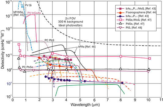
Figure 21. Room temperature detectivity values versus wavelength for a number of MWIR and LWIR detectors. The solid lines are reference commercial detectors [159]. The dashed lines represent the performance of new T2SL QCIPs [160]. The lines with data markers are experimental data. It is clear that the commercial SWIR detectors (PV Si and PV InGaAs) have detectivity values several orders of magnitude higher than many MWIR and LWIR devices. Reproduced from [161]. CC BY 4.0.
Download figure:
Standard image High-resolution imageFor a more detailed look into optical receiver design beyond the photodetectors, an excellent reference can be found in Stephen B Alexander's 'Optical Communication Receiver Design' textbook [162]. As discussed previously, this review will narrow the scope to focus specifically on developments in MWIR and LWIR photodetectors. This is motivated by the improved atmospheric transmission properties of the MWIR and LWIR atmospheric bands in optical SatCom [25, 163]. The detector can be a major limiting factor in the overall performance that can be achieved for an optical SatCom link, which is why the focus will be on detectors. To that end, this review will cover the current commercial offerings in the MWIR and LWIR, as well as novel upcoming detector materials at the cutting edge of photodetector technology. This will include bulk detectors such as HgCdTe (MCT) and InSb, which are the two leading MWIR and LWIR photodetectors on the market [164], as well as quantum well infrared photodetectors (QWIPs), quantum cascade detectors (QCDs), type II super lattices (T2SLs), quantum dot infrared photodetectors (QDIPs), 2D material detectors such as graphene, and NLO solutions based in wavelength conversion from the MWIR and LWIR to the SWIR.
4.1. Noise behavior
Another important consideration for photodetector performance is noise modelling. In optical SatCom applications, noise sources typically consist of the transmitter noise (called relative intensity noise (RIN)), Johnson–Nyquist or thermal noise, background noise from light other than the transmitted signal, dark current, and shot noise [162, 165–168]. Additionally, there are some small but important differences in noise modelling depending on whether the photodetector is a PIN or an APD diode that we will also cover. This discrepancy arises due to the significant internal gain present in APDs, which amplifies the signal as well as the noise (sometimes referred to as excess noise) [169]. There are also atmospheric turbulence effects and beam wander that affect link availability, but these are not direct results of the governing physical principles of photodetectors and so are addressed in the wavelength selection portion of the review. There have been a number of reports over the years on numerically modelling noise in FSO receivers [165–168, 170, 171]. The noise modelling reported here should serve as a good introduction to the topic, but those seeking more in-depth derivations and discussion on receiver modelling should refer to those works.
Starting with RIN, we can consider a practical laser transmitter. The output power of a real laser is not constant in time, and instead fluctuates due to a variety of factors such as thermal changes in the laser cavity and gain medium, quantum mechanical factors beyond the scope of this review, and vibrations in the mechanical housing of the laser. These are typically modelled by introducing a time-dependent term to the optical power of the laser [162]:

where Po is the average power and  represents the time-varying fluctuations in laser power. Typically the time varying term is considered noise and represented using the RIN, defined as the mean-square noise power divided by the mean power squared [172]:
In terms of modelling the impact of the RIN on the photodetector output, it is common to add a current source in terms of the power spectral density (units of  ):
):

where ip is the DC current associated with the average power Po and the 2nd term represents the quantum shot noise of the source. An alternate definition in terms of the variance in measured current can also be used, defined as [171]:

where R is the reactivity of the detector at the wavelength of interest and B is the bandwidth of the detector. If the detector is an APD, we must also consider the excess noise factor of an APD, which is defined as [173]:
where G is the gain of the APD, and K = β/α is the ionization ratio where  is the ionization coefficient for electrons and
  is the ionization coefficient for holes in the APD. In this case, the variance in current due to RIN is then defined as:

We will also see the excess noise factor in the following section on shot and thermal noise, as this excess noise factor is the main reason PIN and APD devices differ. While the RIN is included for the sake of completeness, RIN is usually a negligible source of noise for FSO [154].
Moving on to thermal noise, there will be thermal noise in the photodetector as well as the other electronic components comprising the signal analysis circuit. This is caused by temperature-induced changes to the resistance of an electronic component and was derived by Johnson [174]. The RMS voltage change related to temperature is defined as [175]:

where k is Boltzmann's constant, T is absolute temperature in Kelvin, and B is the bandwidth of the detector. The variance in current associated with the thermal noise is given by:
where RL is the load resistance and F is the noise figure of the system, which is defined as the ratio of input SNR to output SNR to account for noise induced by the measuring system. A similar noise current can be attributed to all components in the electronic circuit between the photodetector and the demodulated signal, so it is important to include thermal noise considerations for the amplification and analysis stages as well.
The background noise can be broadly considered as any light that passes through the optical filters after the receiver telescope that is not the desired optical signal. This can come from a number of sources in FSO, although it is often attributed to a combination of blackbody radiation and light reflected off of the Earth's surface and atmosphere [165, 176]. The amount of background power incident on the receiver will depend mainly on how narrow the optical filter bandwidth will be, as well as the field of view of the receiver telescope. While it may seem that the straightforward option is to then target a narrow field of view system with a narrow optical filter to reduce background, it must be considered that narrow optical filters typically have higher losses and a minimum field of view must be maintained so that the telescope can accurately track the satellite [162]. There is also a time varying component to background radiation, as it will change with time of day and weather/cloud cover. The background radiation power can be estimated as [170]:
The 1st term represents reflected solar radiation while the 2nd term represents blackbody radiation. Ar is the receiver's primary area, FOV is the receiver field of view,  is the optical filter's bandwidth, Rad is the reflected solar radiance, k is Boltzmann's constant, T is the Earth object Blackbody temperature, TA is the atmospheric attenuation, TF is the optical transmission of the filter, c is the speed of light, h is Planck's constant, and
  is the factor of radiant absorbance that relates perfect blackbody spectral radiance to the graybody spectral radiance. We can then use this estimated background power to estimate the current variance as [165]:

Most photodetectors also have a dark current at the output that must be accounted for. As the name implies, the dark current is present when the photodetector is not illuminated. It can be attributed to thermally excited carriers, surface recombination, tunneling between the conduction and valence bands, and more. Dark current is at a minimum when the device is unilluminated and tends to increase with temperature as well as the applied reverse bias that many photodiodes use to sweep carriers out of the depletion region more quickly. As a result, cooling the photodetector can help reduce dark current. We will also see in the following sections that some detector designs have inherently smaller dark currents due to the semiconductor band structure and materials selected. This is also the source of a discrepancy between PIN and APD photodiodes, as the dark current is multiplied by the gain of the APD [154]. Thus for a PIN diode and other diodes with no internal gain, we can model the variance in the dark current as [170]:

where ID is the dark current. In an APD, we must multiply the bulk current by the gain and excess noise factor of the APD, while the dark current from surface recombination is unaffected by the gain. This gives us a variance of [154]:

where IDS is the dark current due to surface recombination, G is the APD gain, IDB is the bulk dark current, and F is the excess noise factor.
We close out this section by considering the shot noise of the photodetector. Shot noise is the result of the flow of charge carriers across a potential barrier being an inherently non-uniform process governed by a Poisson distribution [177]. We can also consider the shot noise as caused by the photogeneration of charge carriers in a photodetector, as the statistics of photons arriving at the photodetector is also modelled by a Poisson distribution. This does not change the model for shot noise, but it is interesting to note that the two are effectively indistinguishable. However the number of charge carriers crossing the pn junction of a photodiode each second is so large that the Poisson distribution for shot noise can be effectively approximated using a Gaussian distribution without much loss of accuracy [177]. The variance in current associated with shot noise can be defined in terms of the DC current flowing through the device:

and, with all of the current variances described, we can define the total variance in current as the sum of all variances:

In conclusion, we can see that while noise modeling for photodetectors is complex and made up of several different physical processes, accounting for noise is relatively straightforward once each source of noise is broken down and analyzed individually. Now, we will look at the state of the art for MWIR and LWIR detectors.
4.2. MWIR state of the art
There are a wide variety of available MWIR detectors across the commercial and research sectors targeted at FSO applications. In order to keep things organized, we will place detectors into one of these two categories. Commercial detectors are developed enough to the point where they can be manufactured with a reasonable degree of reliability and in high enough quantities to support a commercial market. While active research is still on-going for commercial detectors, they are generally closer to fulfilling their theoretical maximum performance than photodetectors in the research category. Research photodetectors are up and coming photodetectors that have several potential benefits over commercial detectors, whether that is increased manufacturability, higher sensitivities, faster response times, higher operating temperatures, lower dark currents, or wider wavelength ranges. These detectors may still be 5–10 years from being commercially viable and still have significant room for growth. However, they are still covered in this review as potential avenues for high performance photodetectors in the near future. It is also important to note that we are only covering photodetectors in this review and not thermal detectors, which operate off different physical principles than photodetectors. The main reason for this is that thermal detectors have an extremely slow response time (milliseconds to seconds) that makes them unsuitable for high-speed communication.
Starting with commercial MWIR detectors, the main two photodetectors on the market currently are HgCdTe (mercury cadmium telluride or MCT) and indium antimonide (InSb). MCT detectors are popular and can even be considered the dominant MWIR technology due to their highly tunable bandgap (from 1 to 30 µm wavelength absorption) and low lattice mismatch, allowing relatively straightforward fabrication of high quality heterostructures [178]. MCT detectors also have high optical absorption coefficients, high quantum efficiency, and long carrier lifetimes leading to higher possible operating temperatures [179, 180]. While MCT detectors can be fabricated using metal organic chemical vapor deposition and molecular beam epitaxy methods, they can be somewhat expensive due to the high cost of the substrate ZnCdTe used for epitaxial growth, and there can be uniformity issues for MCT detectors targeting longer wavelengths due to the difficulty of controlling the material composition to the degree required for such narrow bandgaps [164]. Despite their dominant status in the market, MCT detectors have some negatives as well. One main disadvantage is that MCTs have relatively large dark currents at room temperature due to band to band tunnelling, which can be partially offset by cooling the detector [174]. Background limited performance has been shown to be possible at room temperature, but this requires at least 90% of background radiation to be removed which can be difficult in optical SatCom applications due to celestial background [181]. Despite these drawbacks, MCT remain a popular choice for MWIR and LWIR detection. Recent state of the art devices have been reported by Rothman et al on an MCT APD with a 145 MHz bandwidth and a cut-off wavelength of 5 µm at a temperature of 77 K [182], and Perrais et al reported a 600 MHz RC-limited bandwidth MCT APD with 5.2 µm cut-off wavelength and a 600 MHz bandwidth at an operating temperature of 80 K [183]. If the Cd composition is kept below 0.5, theoretical bandwidths of 1 GHz are predicted [184]. One immediate observation is that the operating bandwidths of state-of-the-art MCT detectors are too low for gigabit direct detection SatCom, and this is a difficult issue to solve as the shorter carrier lifetimes allowing for wider bandwidths also increase the dark current, and thus decrease the detectivity and increase the minimum detectable power. As a result, there will always be a trade-off between these two figures of merit that make it difficult to optimize a MWIR device for optical SatCom.
The main competitor to MCT on the market currently is InSb. The advantages over MCT include a higher stability, lower fragility, and better yield over MCT devices due to the leveraging III–V fabrication techniques [185, 186]. Despite these strengths, there are considerable negatives as well. For example, InSb still suffers from some fabrication issues due to the large range of lattice constants involved, which can be exacerbated further when arsenic (As) is added to further modify the bandgap for MWIR applications. This lattice constant mismatch leads to increased leakage current due to increased dislocations, which has the effect of increasing the dark current and decreasing the detectivity of the device [187]. A state-of-the-art InSb detector was reported by Ibrahim et al grown on gallium arsenide (GaAs) with a bandwidth of 8.5 GHz at 300 K, showing the respectable performance at room temperature at gigabit speeds is possible with InSb, although the detectivity and thus minimum detectable power is still several orders of magnitude off from the comparable SWIR detectors [188].
Now that commercial detectors in the MWIR have been covered, we will move on to state-of-the-art research detectors. A popular technology is QWIPs based on AlGaAs/GaAs quantum wells grown on GaAs substrates [164]. This leverages the mature GaAs growth technologies, and allows for a fine degree of control of the band structure of the device [189]. The GaAs/AlGaAs structures can cover the 8–12 µm range, while utilizing strained InGaAs/AlGaAs allows access to the MWIR [190]. A benefit of this approach is a low cost versus MCT detectors, but the devices currently suffer from low quantum efficiencies and low operating temperatures [191]. The basic structure of a QWIP is repeating two-layer structures of materials with different bandgaps, which approximates a series of quantum wells if the layers can be made thin enough (typically on the order of nanometers). The basic operating principle is that electrons in the ground state of the quantum wells are then excited to higher levels through photon absorption, generating photocurrent [192]. An example of the general band structure of a QWIP is illustrated in figure 22. Another promising property of QWIPs for high speed applications are the very high electron mobility and picosecond-scale carrier transit times, meaning that QWIPs with a theoretical bandwidth greater than 100 GHz have been predicted, and a number of practical devices have been fabricated with up to 30 GHz bandwidths [193, 194].
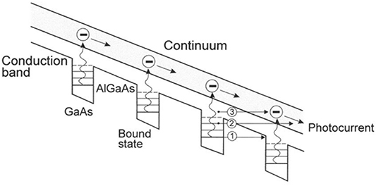
Figure 22. One possible band structure for a AlGaAs/GaAs QWIP. The electrons are excited by photons to the upper states of the quantum well, escaping into the continuum states to generate photocurrent. Reprinted from [195], with the permission of AIP Publishing.
Download figure:
Standard image High-resolution imageDespite these promising features, there are also several drawbacks to the QWIP design. The short carrier lifetime in QWIPs that provides them with such large bandwidths also makes them more sensitive to dark current, decreasing their detectivity [196]. This increased sensitivity to dark current also means that QWIPs have trouble operating at high temperatures [197]. Another problem unique to QWIPs arises as a result of their use of quantum confinement, thanks to their quantum well structure. Many QWIPs can only absorb light incident upon the detector when there is quantum confinement in one of the perpendicular axes. This has the consequence of many QWIPs being unable to absorb normal incident light. While the problem has been solved through the addition of scattering gratings in front of the detectors, this increases complexity and fabrication costs [198, 199]. The absorption efficiency in QWIPs is also low and has significant room for improvement [199].
A variant of the QWIP design is the QCD. Instead of alternating periods of two layers, a QCD may have many layers in a period. The materials and thicknesses are selected so that each layer has a slightly lower energy level than the previous layer, which lets carriers tunnel through the barrier layers until it reaches the ground state of the absorbing layer [164]. This structure has the benefit of significantly reducing the dark current of the detector, and thus the potential stable operating temperature [200]. As photovoltaic devices, the QCD can be operated at zero bias, providing a potentially higher SNR over QWIPs as well due to the reduction in noise [201]. QCDs are also capable of high speed operation, as according to theoretical analysis the 3 dB cut-off frequency for InGaAs/InAlAs QCDs is 65 GHz [202]. In practical devices such as the one reported by Zhao et al QCDs can cover the SWIR to the MWIR, although most results are in the SWIR band. Response times of up to 42 GHz in the SWIR imply plenty of room for improvement in the 9 GHz MWIR QCD that was reported [203, 204]. The sensitivity of QCDs is also tunable through the addition of further stages to the cascade structure [205]. However QCD structures still suffer from the normal incidence rejection rule that requires the use of complicated and expensive grating structures to scatter the incoming light [189]. A number of high speed QCDs have been reported: Zhou et al was mentioned previously, Hofstetter et al reported a room temperature InP-based InGaAs/InAlAs QCD with a 4 GHz bandwidth and maximum modulation frequency of 23 GHz at 5.35 µm, and Dougakiuchi et al reported a 5 GHz bandwidth QCD with a response up to 26 GHz [202, 203, 206].
Adjacent to QCDs are interband cascade infrared photodetectors (ICIPs), with the major difference being the dependence on interband instead of intersubband transitions. A common material for ICIPs is the InAs/AlSbGaSb family [129]. The structure is typically an electron injector region, a hole injector region, and an absorption region. The thickness of each stage in this material family can be much thinner than the diffusion length in InAs/GaSb, allowing carrier transit time to be short with multiple stages. This allows ICIPs to maintain high absorption efficiency while operating at higher temperatures [207]. ICIPs using this material in the MWIR have been shown to be capable of higher detectivity and SNR over MCT detectors [208]. ICIPs are less suited to higher speed operation than QCDs, however. This is caused by the longer phonon scattering times (on the order of nanoseconds) due to the Shockley–Read–Hall and Auger recombination [209]. This longer scattering time allows ICIPs to attain higher peak responsivity and lower dark current than comparable QCDs, so there is a trade-off between the two [210]. Several ICIP devices have been reported as well: Lotfi et al characterized the frequency response of an ICIP with a bandwidth of 1.3 GHz, which was further boosted to 7 GHz using a five-stage configuration. Moreover, other InAs/GaSb based devices have achieved similar performance [211–213].
Other MWIR photodetector designs have focused on higher operating temperatures, higher efficiencies, and lower costs. One such design is the T2SL. T2SLs are based on repeating monolayers of InAs and GaSb grown on GaSb substrates [214, 215]. Generally performance between T2SLs and MCT are comparable, with the main difference being T2SLs being capable of operation at higher temperatures [216]. The ICIP structures described in the previous paragraph are an example of a T2SL based structure. One issue in reported devices so far is a lack of reporting on the 3 dB bandwidth of T2SL devices in the MWIR [217]. T2SLs offer high cut-off wavelength tunability and favorable carrier properties for MWIR detection [218]. Historically InAs/GaSb was a popular material group for T2SLs in the MWIR, but recent developments have focused on gallium free fabrication due to simpler growth methods. Ga based devices remain popular for LWIR detection, however. Optimization work still needs to be performed in this area as well, so potential device improvements could be reported in the next few years [219, 220]. One disadvantage is that T2SL structures can suffer from high non-thermal noise due to high trap assisted tunnelling [221]. A high performance T2SL InAs/GaAsSb device is reported by Chen et al with a cut-off wavelength of 5.3 µm at 300 K, and a 3 dB cut-off frequency of 2.4 GHz for a 40 µm diameter device under a −5 V negative bias [217]. A good review of other Sb based devices can be found in [222].
Another interesting MWIR photodetector is based on QDIPs [223–225]. QDIPs are based on intersubband transitions like QWIPs, with the main difference being full 3D confinement due to quantum dots being a 0th dimensional quantum structure. QDIPs have the advantage of allowing normal incidence detection, so no need for grating couplers in their designs [180]. They are also expected to have lower dark current, higher operating temperature, and lower cost when compared to MCT detectors [226]. Quantum dots also have highly tunable bandgaps that depend on their size [227]. The main challenge in QDIP development so far is increasing the low absorption quantum efficiency. One popular method of fabrication quantum dots for use in QDIPs is colloidal QDs, often grown in solution through precise chemical processes. There are two geometries for turning colloidal QDs into photodetectors: planar and vertical, as illustrated in figure 23.
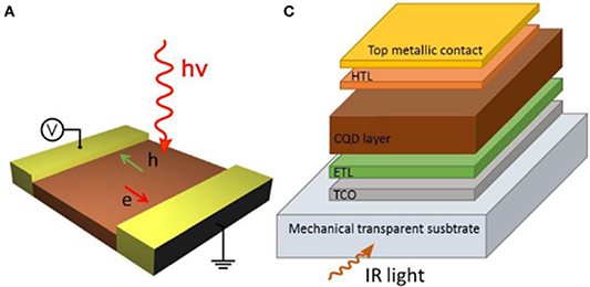
Figure 23. Planar QDIP (left) and vertical QDIP (right). Planar is simpler to fabricate while vertical allows near-zero bias operation due to the built-in electric field of the diode. Reproduced from [228]. CC BY 4.0.
Download figure:
Standard image High-resolution imageWhile UV-visible quantum dots have reached the commercialization stage, infrared QDs have significant development work required before they can reach a similar stage [229]. This is in part due to the difficulty of controlling the colloidal reactions that produce QDs to a high degree of repeatability and uniformity [230]. Another issue is that they can be unstable in air depending on the material choice due to oxidation [224]. The main source of noise in QDIPs tends to be 1/f noise [231, 232]. The absorption issue in QDIPs can be attributed to the short carrier diffusion length (50–100 nm) so the generated photocarriers are only collected near the electrodes. This low carrier mobility significantly limits the potential detectivity of QD-based devices [233]. QD performance is also affected by charge traps that can form on the surface of the dots, leading to slower response times and lower sensitivities [234]. There is also a lack of bandwidth reporting for MWIR QD devices, so it is difficult to determine if they would be suitable for high speed detection [235, 236]. Yet another issue is the low fill factor that can be achieved with one layer of quantum dots on planar QDIP structures, leading to low quantum efficiency and absorption [237]. One method of improving QDIP performance is to supplement QDIPs with 2D materials such as graphene [228].
Two-dimensional materials offer an interesting avenue for MWIR photodetection, both standalone and through integration with QDIPs [161, 216, 238, 239]. A hybrid QD/graphene structure has been demonstrated recently by Wu et al [234]. The concept dates back to 2012 and promises the potential for higher detectivity, high speed, low cost, and scalable IR detectors [240]. When considering standalone 2D materials, they can potentially offer tunable bandgaps through modifying the thickness of the material, reduced cost, increased response speed, and higher sensitivity [241]. 2D materials have demonstrated extremely high gains up to  , which contributes to high responsivity [240]. Sensitivity can be further enhanced by incorporating optical cavity structures with the 2D materials, although this narrows the detection wavelength band significantly due to the high selectivity of optical cavities [242, 243]. This high responsivity comes at the cost of slow response speeds (<10 Hz) which would severely limit their application to high-speed IR detection. One notable exception to this are gold patched graphene nanostripes from Cakmakyapan et al which achieved a responsivity of 11.65 A W−1 and operation speed >50 GHz at a wavelength up to 20 µm [244]. Black phosphorous has also been a promising 2D material in the MWIR as it possesses a highly tunable bandgap and high carrier mobility, with gains as high as
  [245, 246]. Black phosphorous has also been combined with arsenic (bPAs) to create photodetectors with higher detectivities than MCT in the MWIR [216]. While 2D materials have significant potential for IR detection, their current performance at high operating temperatures lags behind MCT and T2SL devices [247, 248]. The low absorption due to very thin active layers (100–200 nm) and short carrier lifetime leads to a tradeoff between responsivity and device speed in most 2D material based detectors as well [216]. Future research should prioritize increasing detectivity and reducing noise if 2D materials are to be useful for practical applications [241].
The final MWIR detection technology to be considered in this review is the use of NLO wavelength conversion. This method is unique compared to all the previous detectors mentioned, as the goal is to avoid MWIR direct detection entirely. Instead, using a NLO phenomenon known as sum frequency generation (SFG), it is possible to convert the incoming MWIR signal into a SWIR signal so that the better developed SWIR technology (such as Si APDs) can be used instead. The basic principle of SFG is illustrated in figure 24, and a detailed derivation can be found in the reference textbook from Boyd [100].

Figure 24. The process of SFG. The three optical waves are the pump ( ), signal (
 ), and idler (
 ), where the idler output frequency is the sum of the pump and signal frequencies.
Download figure:
Standard image High-resolution imageThe process involves coupling a pump laser into a nonlinear crystal such as PPLN along with the incoming MWIR light that would constitute the transmitted signal. Through careful selection of the pump wavelength, it is possible to produce an output idler signal with a wavelength around the peak responsivity of SWIR silicon APDs. For example, a 3.385 µm MWIR signal combined with a 1.064 µm laser from a Nd:YAG or Nd:YVO4 solid state laser would produce an output idler with a wavelength of 809 nm. This is calculated by considering the conservation of energy for the process, which is often represented using the phase matching condition. For SFG, this formula is [100]:

A major benefit of nonlinear wavelength conversion is that NLO processes are effectively instantaneous even over the timescales involved for gigabit communication, so the full bandwidth of the SWIR detector can theoretically be utilized. This approach has been reported with FSO communication in mind [249]. Hao et al reported a system based on NLO generation of a MWIR transmitter using DFG as well as a receiver based on SFG. The MWIR wavelength of 3.594 µm was combined with a 1.083 µm pump to produce a 1.550 µm idler at the detector [59]. The main issue that has plagued this approach so far is low conversion efficiencies; the detector created by Hao et al converted a 9.3 mW of 3.593 µm signal into  of 1.55 µm power, negating a significant portion of the sensitivity gain from using SWIR detectors. One possible solution to this problem is to use intracavity structures, where efficiencies as high as 30% have been reported for different nonlinear processes [250]. If the efficiency can be improved to this level, NLO receivers could outperform other direct detection MWIR schemes in both minimum detectable power and bandwidth [116].
To close out this section of the review, several representative devices for each of the detector structures discussed are listed in table 3 below, with the relevant device figures of merit listed for each reference. The NLO-based detectors are included assuming a −20 dB efficiency penalty and silicon APDs as the selected SWIR detector. This efficiency penalty is conservative in order to illustrate that, if higher SFG efficiencies can be obtained, then NLO detectors can potentially outperform direct MWIR detection by a significant margin. The main conclusion we can draw is that MWIR detectors have advanced significantly in the last decade, but there is still a gap between MWIR detector and SWIR detector performance. The main drawbacks in the context of optical SatCom are the lower detectivities and narrower frequency bandwidths. While gigabit level communication may be possible in LEO with state-of-the-art devices (this is examined in more detail in the section 5), the increased performance in poor weather from the MWIR wavelengths do not counteract the overall poor performance of MWIR detectors when compared to the SWIR. If the last decade is any indication, then the next 5–10 years should produce a number of significant advancements in MWIR detection, and so the advent of MWIR FSO communication may not be far off.
Table 3. A variety of state-of-the-art MWIR detectors across multiple photodetector models. N/A indicates the paper did not report the indicated quantity.
| Material and structure | Cut-off wavelength ( ) ) | Responsivity (A W−1) | Dark current (or density) | Response speed (3 dB) | NEP/detectivity | References |
|---|---|---|---|---|---|---|
| MCT APD | 5 | N/A | N/A | 145 MHz | N/A | [182] |
| MCT APD | 5.2 | N/A | N/A | 600 MHz | N/A | [183] |
| HgTe/graphene quantum dots | 3 | 100 A W−1 @ 300 K | N/A | 1.4 kHz |
 Jones Jones | [251] |
| InSb on GaAs substrate | 5.33 | 1.8 @ 77 K | N/A | 8.5 GHz @ −2.5 V |
 Jones Jones | [188] |
| InAs/GaAsSb T2SL | 5.3 | 0.1 @ 300 K | 1  @ −0.1 V @ −0.1 V | 2.4 GHz @ 300 K | N/A | [217] |
| InGaAs/InAlAs QCD on InP substrate | 5.35 | 0.0032 @ 100 K | N/A | 4 GHz | N/A | [202] |
| HgTe quantum dots | 5.25 | 0.08 A W−1 @ 140 K | N/A | >1 MHz |
 Jones Jones | [174] |
| InGaAs/InAlAs QCD on InP substrate | 4.3 | 0.0078 @ 300 K | N/A | 9 GHz |
 Jones Jones | [203] |
| InAs/GaSb on GaAs | 6.4 | 0.56 A W−1 @ 77 K |

 @ −0.1 V @ −0.1 V | N/A |
 Jones Jones | [218] |
| QCD | 4.5 | N/A | N/A | 5 GHz | N/A | [206] |
| PdSe2/Si | 4.6 | 0.726 @ 300 K | N/A | N/A |
 Jones Jones | [252] |
| ICIP on GaSb substrate | 4.2 | 0.24 @ 300 K | N/A | 1.3 GHz | > Jones Jones | [211] |
| ICIP on InAs substrate | 5.3 | 0.1 @ 300 K | 3.97  @ −0.1 V @ −0.1 V | 2.4 GHz | N/A | [217] |
| InAsSb photodiode | 3.7 | N/A | N/A | N/A |
 Jones @ 170 K Jones @ 170 K | [253] |
| ICIP on InAs substrate | 5 | 0.067 @ 300 K | 0.094  @ −0.1 V @ −0.1 V | 7.04 GHz |
 Jones Jones | [212] |
| HgTe colloidal quantum dots | 5 | 1 A W−1 @ 85 K | N/A | 1 kHz |
 Jones Jones | [254] |
| InAs/GaSb UTC on GaSb | 5.6 | 0.1 @ 300 K | 0.6  @ −0.5 V @ −0.5 V | 6.58 GHz |
 Jones Jones | [213] |
| Black phosphorus | 3.39 | 82 A W−1 @ 300 K | 5  @ 3 V @ 3 V | 2.2 kHz | N/A | [245] |
| BPAs | 3.9 | N/A | N/A | 117 kHz |
 Jones Jones | [255] |
| BP integrate Si on insulator | 4 | 2 A W−1 | ∼10  @ 2.5 V @ 2.5 V | N/A |
 Jones Jones | [256] |
| SFG nonlinear detector | 5 | 0.4 A W−1 | N/A | 1 GHz |
 Jones Jones | [116] |
| High-gain T2SL | 8 | 1284 A W−1 | 3.2  @ 77 K @ 77 K | N/A |
 Jones Jones | [257] |
4.3. State of the art LWIR detectors
We will now look at the state-of-the-art in LWIR detectors. This section will be significantly shorter than the MWIR section, as the devices used in the LWIR have significant overlap with the detectors used in the MWIR in terms of structure and device physics. As a result, we will avoid repeating information unnecessarily and instead look at the differences and provide a similar overview of several representative examples of the state of the art in the LWIR band. This will conclude the detector portion of the review.
Starting with MCT detectors, these are an equally popular choice for the LWIR, as varying the Cd fraction allows tuning of the bandgap from 1 to 30 µm [178, 258–260]. However, MCT encounters a number of issues in the LWIR that were absent in the MWIR, degrading overall performance for the material. One issue is that the absorption depth of the LWIR in MCT is >5 µm, which is much longer than the diffusion length in the material. This means the quantum efficiency for the LWIR is lower in MCT than it is in the MWIR, and QCDs were in part developed to solve this issue and tend to outperform uncooled MCT detectors using similar LWIR wavelengths [161, 261]. Another issue is the repeatability of manufacturing MCT devices in the LWIR range, due to both the weak HgTe bond as well as the bandgap becoming so narrow that the smallest change in Cd fraction can lead to large changes in the bandgap properties, lowering device yield significantly [262]. Nonetheless, good performance has been reported for MCT detectors in the LWIR, with a 1 GHz bandwidth MCT diode with >30% quantum efficiency being demonstrated at a temperature 77 K [263]. Cryogenic cooling is generally required for maximum performance in most LWIR detector technologies, due to thermal noise posing a large issue for the narrow bandgaps required for direct LWIR detection. Operation temperatures above 200 K are difficult to guarantee as the devices begin to suffer from significant Auger recombination, lowering detectivity [264]. QWIPS offer a promising alternative to MCT detectors, with larger frequency bandwidths and higher saturation intensities [265]. Additionally, room temperature QWIPs with reasonable performance have been reported through the use of metamaterials to decrease dark current and increase responsivity [266].
The NLO approach using SFG mentioned previously is also possible for the LWIR region, although there are some key differences to consider. The first major roadblock in utilizing nonlinear wavelength conversion is that the normal nonlinear crystals used for this purpose are only transparent out to 5 µm, and thus cannot be used for frequency conversion to longer wavelengths. The solution that has been in development since the late 2000s is OP-SCs. These effectively serve the same role as periodically poled nonlinear crystals, but take advantage of the much larger transparency region of GaAs and GaP to access wavelengths from 1 to 18 µm [267, 268]. The basic concept remains the same as the SFG detector proposed for the MWIR, with the only difference being the wavelengths utilized. If we assume the incoming light has a wavelength of 10 µm, then it can be combined with 1550 nm light (as an example), producing ∼1340 nm light, which is located in the detection range of high speed InGaAs detectors [117]. The output wavelength can be modified by changing the 1550 nm light to a different wavelength depending on the desired result. These devices are exciting in their potential to open a much larger wavelength band for NLO applications, but fabrication techniques are still being researched to increase the quality, scale, repeatability, and cost of these devices. Similar to the previous section, table 4 serves a summary of the important device metrics for a variety of state of the art LWIR detectors.
Table 4. A variety of state-of-the-art MWIR detectors across multiple photodetector models. N/A indicates the paper did not report the indicated quantity.
| Material and structure | Cut-off wavelength ( ) ) | Responsivity/quantum efficiency | Dark current (or density) | Response speed (3 dB) | NEP/detectivity | References |
|---|---|---|---|---|---|---|
| MCT pin photodiode | 10 | ∼30% | N/A | 1 GHz @ 77 K |
 W Hz−1 @ 1.5 GHz W Hz−1 @ 1.5 GHz | [258] |
| MCT | 12 | N/A | N/A | N/A |
 Jones Jones | [259] |
| Graphene nanoribbons | 20 | 11.5 A W−1 | N/A | 50 GHz | 1 pW 
| [244] |
| Ti2O3/graphene quantum dots | 10 | 300 A W−1 | N/A | 1 kHz # 300 K |
 Jones Jones | [273] |
| InAs/InGaAs | 13 | N/A | N/A | N/A |
 Jones Jones | [274] |
| QWIP on GaAs substrate | 10 | 11% | N/A | 8 GHz @ 77 K |
 Jones Jones | [275] |
| InAs/GaSb T2SL | 18.8 | 4 A W−1 @ 80 K | N/A | N/A |
 Jones Jones | [276] |
| QWIP on GaAs substrate | 9.3 | 0.45 A W−1 | N/A | 19 GHz @ 82 K | N/A | [277] |
| QWIP on GaAs substrate | 9 | N/A | N/A | 75 GHz @ 100 K | N/A | [278] |
| QWIP on GaAs substrate | 9 | 0.2 A W−1 | 3.5 mA @ 0.5 V | 4 GHz @ 300 K | ∼2 Jones Jones | [199] |
| QCD on GaAs substrate | 9 | 50 mA W−1 @ 0 V | N/A | 1.4 GHz @ 295 K |
 Jones Jones | [279] |
| MoO3 | 10 | 0.4 A W−1 @ 300 K | N/A | 10 kHz |
 Jones Jones | [280] |
| PdSe2 photodiode | 10.6 | 42.1 A W−1 @ 1 V | 10  @ 1 V @ 1 V | N/A |
 Jones Jones | [281] |
Now that we have considered a broad spectrum of MWIR and LWIR detectors, we can conclude by summarizing the findings. We can see that MCT and InSb maintain dominant market positions due to their unique mix of high-level performance when cooled and acceptable performance at higher temperatures for many infrared applications, although the bandwidth is lacking for high speed direct detection applications. The QWIPs harness mature III–V growth techniques to produce detectors with a high degree of uniformity and low cost while covering the MWIR and LWIR, with the downsides of lower quantum efficiencies, poor performance at room temperature, and the inability to absorb normal incident light. T2SLs can have high operating temperatures and cover an extremely wide wavelength range with a high absorption coefficient, but they are relatively expensive to produce and have low yields, inhibiting their ability to be commercialized compared to other competitors. QDIPs have lower dark currents than QWIPs and high operating temperatures, but the long carrier lifetimes that help suppress dark current could lead to lower bandwidths (although bandwidth has not been reported frequently with QDIPs). QDIPs also suffer from repeatability due to the imprecise nature of current colloidal quantum dot fabrication methods, and the overall quantum efficiency of QDIPs is still quite low. Two-dimensional materials offer the potential for high quantum efficiencies, low cost, and relatively straightforward fabrication and processing, while they suffer from weak absorption due to the 100–200 nm thick active region. Finally, NLO wavelength conversion offers the potential to avoid direct detection in the MWIR and leverage the affordability and high performance of existing SWIR detectors, but the efficiency of devices demonstrated so far has been low enough to negate most of the benefit of the improved detectors. Increased efficiencies must be demonstrated before NLO can be pursued in the context of optical SatCom. We can still consider MWIR and LWIR devices to be in the early stages of development, at least compared to the SWIR devices currently available commercially. We can expect significant improvement as better growth and processing techniques are developed, and there are still promising results being reported that encourage revisiting this topic in 5–10 years for greater performance [269–272]. We will use the metrics reported here in the section 5 to estimate the link budget for a MWIR and LWIR optical SatCom link to answer the question of whether such a link is at least feasible using state of the art transmitter and detector technology in these wavelength bands.
5. Link budget and conclusion
In this section, a link budget calculated for the SWIR, MWIR, and LWIR using OptiWave's OptiSystem software package is presented. While OptiSystem implements complex equations that have been covered in part in this review, we will also briefly describe simpler background formulas used as well as provide reasonable assumptions to come up with a rough link budget estimate for low earth orbit to ground links. This will allow those without access to this software to come up with a rough estimate of a link budget for any wavelength of their choosing. This is meant to be an illustrative example to compare some of the differences that must be accounted for between wavelength bands. One of the assumptions we will be making is that the output power of the lasers is equal across all bands, which is supported by the reported common laser metrics in section 3. As for calculating the minimum detectable power (Pmin), there will be a sample calculation using the detectivity of a SWIR detector to derive Pmin, and the calculation applies to detectivities in the MWIR and LWIR reported in section 4. In order to assure that the detectors are compared fairly, it will be assumed when deriving the minimum power that all detectors have equal active detection areas, as otherwise detector size would be an additional variable that could skew results unfairly. This is a rudimentary link budget to serve as a 'sanity check' that such links are possible, but more detail analysis has been performed numerically for the SWIR band and can be found in the following references from section 4 [150, 165–168, 170, 171, 282–288].
The average power at the receiver in Watts can be expressed as [289]:

where Pt = avg transmit laser power (typ 2 W peak), Gt = transmitter antenna gain (typ 10^11), Gr = receiver antenna gain (typ 10^13), Tt = transmitter losses (abs, scattering, imperfect optical coatings, etc typ 0.5), Tr = receiver losses (abs, scattering, imperfect optical coatings, etc typ 0.5), Ta = atmospheric losses (can vary significantly, best calculated using empirical and statistical models), Ls = geometric loss due to beam spreading.
The transmitter antenna gain can be calculated as:

where [290]:
Here, a is the radius of the telescope aperture in meters, AT is the area of the telescope primary,  is the transmitter wavelength, and
  if the telescope has zero central obscuration. The receiver antenna uses a similar formula [291]:
where  where b and a are the aperture radii of the secondary and primary mirrors, respectively. The third term
  represents losses due to the detector, where for direct detection losses are assumed to be a result of energy missing the detector entirely due to beam spreading, while for heterodyne detection there are several factors such as the local oscillator field distribution discussed in more detail in [291]. The geometric losses due to beam spreading are given by:
where R is the link distance in meters. The geometric loss is the most significant source of loss, typically in the 200 dB range for satellite to ground distances. This is mainly compensated for by the transmitting and receiving optics, although it is important to note the wavelength dependence of both this loss and the antenna gain. An unfortunate downside of this wavelength dependence is that, all else being equal, longer wavelengths will suffer from increased losses overall due to the reduced efficiency of telescopes as shown in equations (31) and (32). As a result, while it is assumed in the OptiSystem simulation that the telescopes in the SWIR, MWIR, and LWIR are the same size, in practical applications it may be necessary to increase the transmitting and/or receiving telescope apertures to account for this increased loss.
At the receiver, we must consider the minimum detectable power to set the link budget, which is largely determined by the detector being used. In order to determine the minimum detectable power, we must know the bandwidth the detector will be operated at, the active area of the photodetector, and the detectivity. The calculation for minimum power requires the NEP at the given detection wavelength and the measurement bandwidth in hertz:

We will assume a bandwidth of 3 GHz to ensure sufficient margin of error for a gigabit link using OOK. As for the NEP, we can derive this from the detectivity of a given detector so long as we know the active area of the photodetector, thanks to the definition of specific detectivity:
where A is the area in cm and  is the specific detectivity. In order to remove area as a potential factor across devices, we will assume all photodetectors have an active area diameter of
  , which is suitable for Gigabit speeds. What follows is a sample calculation for the SWIR, using a detectivity of
  which is attainable for InGaAs detectors at 1550 nm [161]. The detectivity values for the MWIR and LWIR are
  and
and  , respectively [257, 274]
So we can see the minimum detectable power in the SWIR 36 picowatts, or −74 dBm. The MWIR Pmin is 18 picowatts −77 dBm, and the LWIR  is 3.6 nanowatts, or −54 dBm. We can clearly see that while the MWIR and SWIR detectors are somewhat similar in performance, the LWIR is two orders of magnitude less sensitive. It is important to note, the minimum detectable power will be much higher than this value as we also seek to achieve a given bit error rate, which will necessitate a higher power at the receiver than the minimum power given by the NEP. Given that the rough limit of SWIR gigabit sensitivity is −48.9 dBm, we will add a 30 dBm margin to each detector to ensure a satisfactory bit error rate can be achieved [149]. This leaves the SWIR, MWIR, and LWIR minimum powers for the link budget at −44 dBm, −47 dBm, and −24 dBm, respectively. We now have all of the necessary information to create a link budget simulation in OptiSystem. The simulation in OptiSystem can be found in figure 25 below.
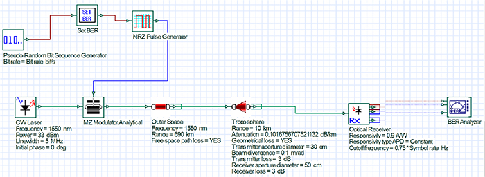
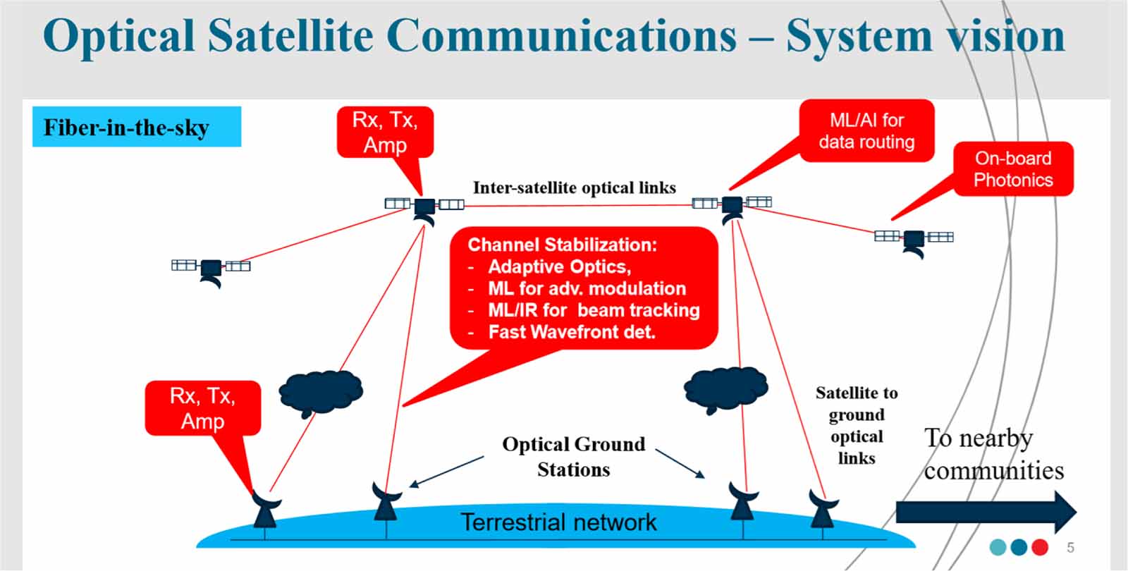
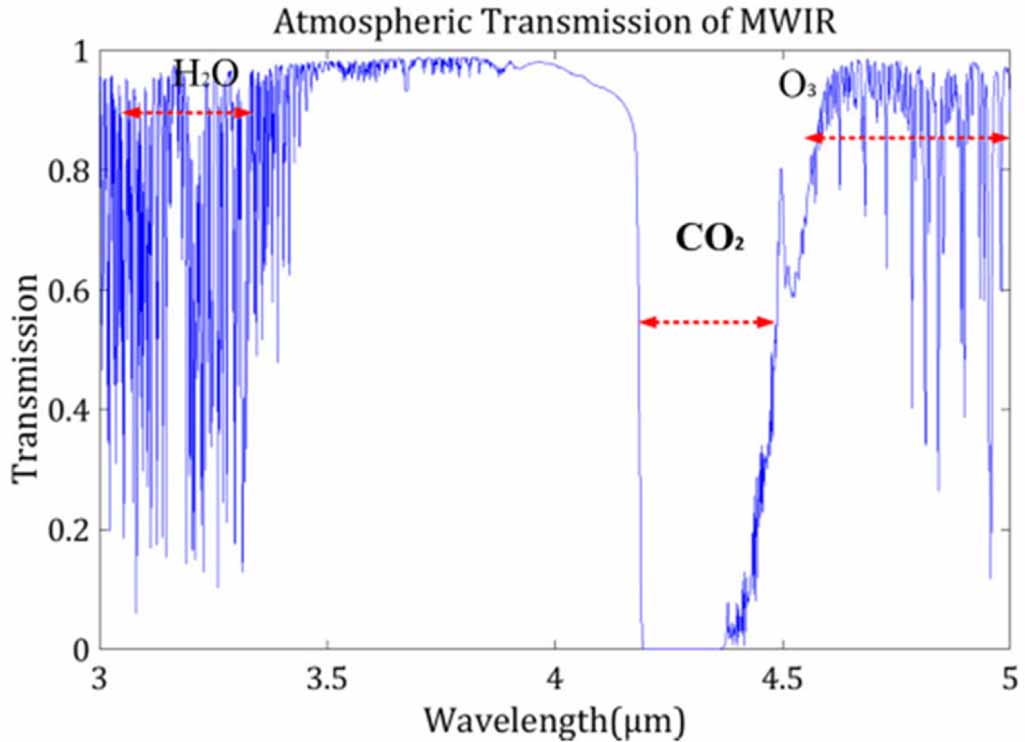
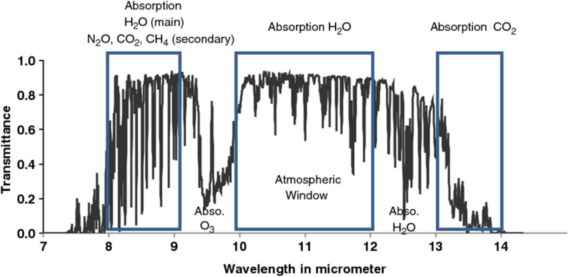
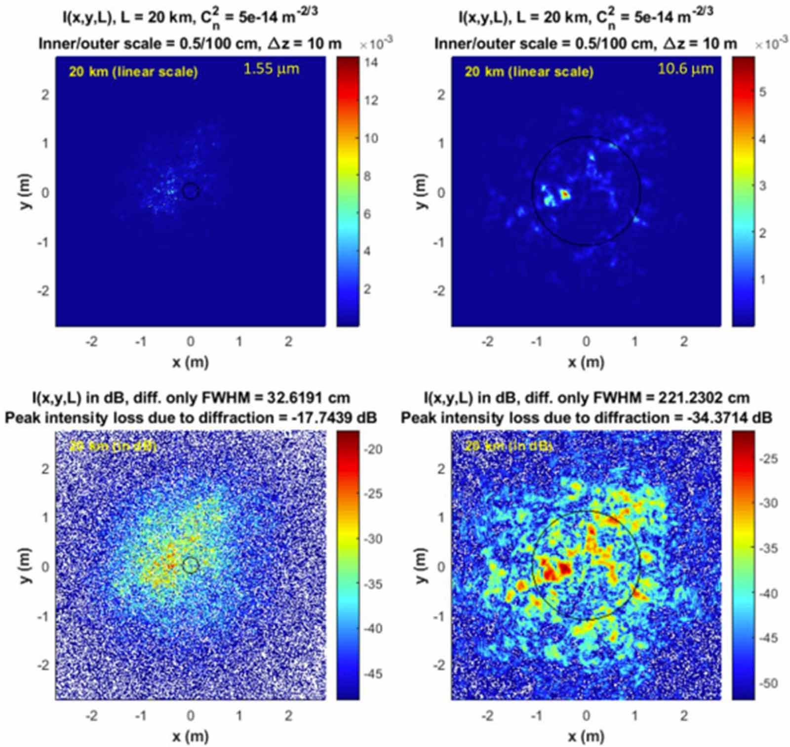
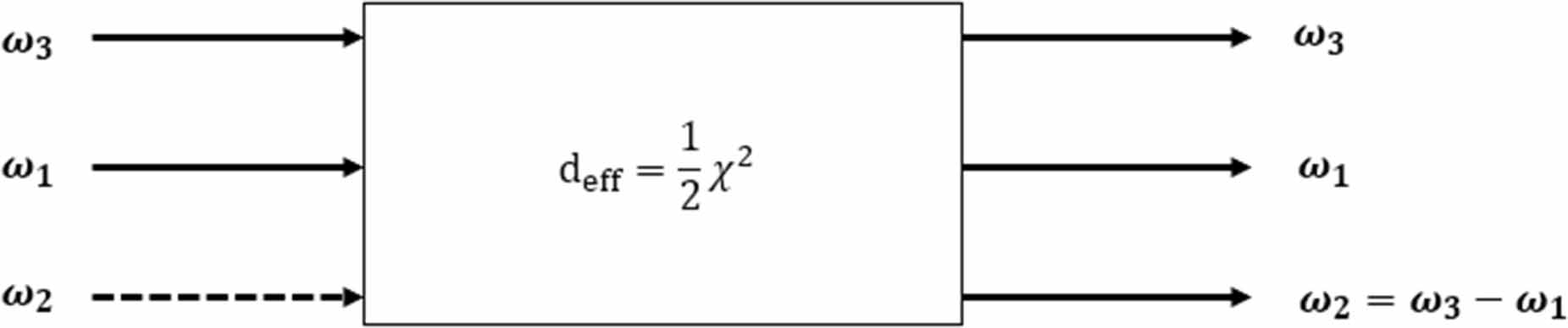
Figure 25. The OptiSystem link budget model. The example provided here is for a SWIR link, with the wavelength and atmospheric attenuation changing for each wavelength band tested.
Download figure:
Standard image High-resolution image
The simulation was run assuming an APD type detector as the receiver in all cases, and the transmitter laser was kept at a fixed output power of 2 W or 33 dBm for each wavelength used. The SWIR, MWIR, and LWIR wavelengths selected for the transmitter were 1550 nm, 3385 nm, and 10 000 nm, respectively. The output of the laser was simulated as a pseuodorandom bit sequence with a bit error rate of  . The transmitted light travels through 690 km of vacuum/free space, which is a reasonable approximation for LEO distances, followed by 10 km of troposphere. The atmospheric attenuation in the troposphere is calculated as a combination of the Kim and Kruse model as well as a gamma–gamma distribution for atmospheric scintillation as covered in section 2. Four visibility values for the atmospheric attenuation were used: 1, 2, 5, and 10 km, meant to represent heavy, moderate, light, and very light weather. The following table shows the power at the receiver as calculated by the simulation, which we then subtract the minimum detectable power derived previously to come up with a link budget for each wavelength band.
In table 5, a negative value for net link budget in dBm indicates that the received power is below the minimum detectable power for a given detector, and so we cannot expect a reliable link. We see that in heavy weather, the MWIR outperforms the SWIR by several dB, but both would struggle to form a reliable link in such conditions. As we move to better weather, the SWIR outperforms the MWIR more as the weather improves. The LWIR struggles to form a reliable link at any visibility, in part due to the significant gap in detector performance for the LWIR versus the SWIR and MWIR. This difference in performance may be surprising at first but is easily explained. Due to the wavelength dependence in equations (32) and (33), the decreased antenna gain from using longer wavelengths offsets the improved performance in poor weather from utilizing longer wavelengths. A few assumptions here could be reasonably challenged; for one, we cannot say with certainty that the efficiency of a MWIR or LWIR will be equal to the efficiency of a SWIR telescope, due to the different optical materials involved. Additionally, the detector sensitivity will likely be lower for practical MWIR and LWIR detectors, as the detectivity values used here are for state-of-the-art research photodetectors. Additionally, if the telescope size is kept constant, there is a loss in gain as the wavelength is increased due to the difficulty of focusing longer wavelengths coupled with increased beam spreading loss. As a result, it may be necessary to increase the diameter of the transmitting or receiving telescope when using longer wavelengths in order to maximize the link budget at longer wavelengths, which maximizes the benefit of the lower losses due to weather effects from longer wavelengths due to reduced scintillation and scattering. Another potential solution for increasing MWIR and LWIR performance is to increase the output power of the transmitter/emitter. Due to the reduced sensitivity and potentially higher noise in the MWIR and LWIR versus the SWIR, the higher output power could partially compensate for these issues (keeping in mind satellite power budget limitations, of course).
Table 5. Link budget estimate for SWIR, MWIR, and LWIR in OptiSystem.
| Wavelength band | Net link budget dBm (V = 1 km) | Net link budget dBm (V = 2 km) | Net link budget dBm (V = 5 km) | Net link budget dBm (V = 10 km) |
|---|---|---|---|---|
| SWIR | −8.25 | 18.56 | 33.39 | 36.09 |
| MWIR | −5.73 | 15.89 | 25.67 | 26.94 |
| LWIR | −32.25 | −19.94 | −14.69 | −14.28 |
In conclusion, we have covered the state of the art in wavelength selection, optical transmitters, and optical receivers for LEO SatCom in the MWIR and LWIR. In general, optical SatCom in the MWIR band is nearing the point where a practical demonstration could be feasibly carried out in the next 5–10 years. The LWIR band, on the other hand, is significantly bottle-necked by the detector technology, and further research will have to occur before a LWIR SatCom link is feasible. It is important to consider the purpose of this review was to determine if MWIR and LWIR LEO SatCom links were possible with state-of-the-art technology, not whether MWIR and LWIR links were more economically viable than the SWIR. The potential additional benefit of using longer wavelengths is offset by the additional cost of components in the MWIR and LWIR. This means that a MWIR or LWIR SatCom link would almost certainly be more expensive and potentially bulkier/heavier than an equivalent SWIR link, at least with current technology. The MWIR is slowly approaching the performance of the SWIR for both the detector and transmitter, while the LWIR still suffers from detectivities several orders of magnitude lower than comparable SWIR and MWIR detectors. As a result, the MWIR is better positioned for a practical demonstration soon, likely in the next decade. Given the lack of experimental data for MWIR or LWIR SatCom missions, the first practical demonstration of such a link will provide valuable data to validate existing empirical models or uncover new behavior for the MWIR and LWIR over such long distances. A practical demonstration would also help illustrate whether the increase in link stability due to lower attenuation is worth the trade-off for the more difficult to use and more expensive MWIR and LWIR components. As an aside, MWIR and LWIR links are also quite promising for terrestrial links, where the much shorter distances involved make the wavelength bands a more attractive option due to the decreased significance of geometric losses that impact SatCom links heavily. The link budget calculations support the idea that the MWIR could potentially see such a demonstration in LEO soon, and so the next 5–10 years will likely be exciting times for optical SatCom as various wavelengths are tested and compared to come up with an ideal solution for a standardized global optical communication network.
Acknowledgments
The authors would like to thank the Optical SatCom Consortium (OSC) and the National Research Council (NRC) of Canada for the support of the project. The authors would also like to thank OptiWave for providing access to their OptiSystem software for link budget modeling and Michel Bellemare of MDA and Dr Siegfried Janz of NRC for helpful discussion on the transmitter, wavelength selection, and modulation review packages during the OSC Roadmapping process.
Data availability statement
The data that support the findings of this study are available upon reasonable request from the authors.