

Abstract
Enhancement cavities (ECs) seeded with femtosecond pulses have developed into the most powerful technique for high-order harmonic generation (HHG) at repetition rates in the tens of MHz. Here, we demonstrate the feasibility of controlling the phase front of the excited transverse eigenmode of a ring EC by using mirrors with stepped surface profiles, while maintaining the high finesse required to reach the peak intensities necessary for HHG. The two lobes of a  mode of a 3.93 m long EC, seeded with a single-frequency laser, are delayed by 15.6 fs with respect to each other before a tight focus, and the delay is reversed after the focus. The tailored transverse mode exhibits an on-axis intensity maximum in the focus. Furthermore, the geometry is designed to generate a rotating wavefront in the focus when few-cycle pulses circulate in the EC. This paves the way to gating isolated attosecond pulses (IAPs) in a transverse manner (similarly to the attosecond lighthouse), heralding IAPs at repetition rates well into the multi-10 MHz range. In addition, these results promise high-efficiency harmonic output coupling from ECs in general, with an unparalleled power scalability. These prospects are expected to tremendously benefit photoelectron spectroscopy and extreme-ultraviolet frequency comb spectroscopy.
Export citation and abstract BibTeX RIS

Original content from this work may be used under the terms of the Creative Commons Attribution 3.0 licence. Any further distribution of this work must maintain attribution to the author(s) and the title of the work, journal citation and DOI.
1. Introduction
The availability of isolated attosecond pulses (IAPs), produced by high-order harmonic generation (HHG), has enabled the observation of attosecond-time-scale dynamics in atoms, molecules, solids and plasmas [1, 2]. While considerable progress has been made scaling up the photon flux at repetition rates below 1 MHz [3], some applications require increasing the repetition rate rather than the number of photons per shot. This is the case for experiments involving the detection of charged particles, where the number of photons per shot is limited by the detection scheme, e.g. coincidence spectroscopy or time-resolved photo-electron emission spectroscopy and microscopy. One application that could particularly benefit from multi-10 MHz IAPs is time-resolved photo-electron microscopy of nano-plasmonic fields [4–6].
Coherently stacking the pulses of a high-repetition-rate modelocked femtosecond laser inside of a passive optical resonator (or enhancement cavity (EC)) provides a convenient way to reach the required peak intensities for HHG, on the order of 1 × 10¹⁴ W cm−2, at repetition rates of several tens of MHz. Recent progress in power scaling and increasing the bandwidth of ECs has allowed to produce attosecond pulse trains with photon energies exceeding 100 eV at repetition rates as high as 250 MHz [7]. Since then, the bandwidth of EC mirrors has been pushed further with the most broadband high-finesse near-infrared EC to date supporting 5-cycle pulses at a central wavelength of 1050 nm [8].
At present, dielectric multi-layer optics that allow the enhancement of near-single-cycle pulses do not seem feasible. Thus, to isolate attosecond pulses from ECs, it is necessary to implement a gating scheme. In [9], several methods have been evaluated and a new scheme termed transverse mode gating (TMG), similar to non-collinear optical gating [10], was identified as the preferred method in terms of robustness and expected photon flux. In TMG, a  mode is excited, which consists of two lobes of contrary phase, separated by an intensity minimum. One of the lobes is delayed with respect to the other by means of an EC mirror with a stepped surface profile (figure 1). After the focus, this delay is reversed by a second, identical mirror. To achieve an on-axis intensity maximum in the focus, the delay is chosen as an odd number of optical half-cycles [11]. The introduced delay leads to a wave-front rotation (WFR) in the focus and therefore to angular dispersion of the individual harmonic bursts produced in a gas target, allowing the selection of an IAP by spatial filtering. A mirror with a slit can be used for efficient output coupling while introducing negligible losses to the excited eigenmode, which has an on-axis intensity minimum on the mirror [12, 13]. Assuming a state-of-the-art EC [7, 8] and 0.7 μJ, phase-stable 17.5 fs seeding pulses centered at 1040 nm, parameters that are within reach with current Yb-based lasers [14, 15], thorough simulations predict that it is possible to generate IAPs with photon energies around 94 eV at a photon flux of 1 × 10⁸ s−1 in a 2% bandwidth, at repetition rates of 10 MHz and higher [9].

Figure 1. Working principle of transverse mode gating. IC: input coupler, HR: highly reflective mirror, SM: HR mirror with a stepped surface profile, CM: curved HR mirror, OM: curved HR mirror with a slit for output coupling, IAP: isolated attosecond pulse.
Download figure:
Standard image High-resolution imageHere, we present an experimental milestone towards the realization of such a source: we produce stepped mirrors and use them to introduce and compensate a delay between the two lobes of a  mode excited in a high-finesse resonator seeded with a single-frequency laser. The observation of an on-axis maximum in the focus is proof that the lobes are indeed shifted by a phase corresponding to the introduced delay, which is confirmed by simulations in excellent agreement to the experimental data. As the size of the mode on the mirrors and the focus size demonstrated in this experiment are in concordance with the parameters assumed for the 3+1D TMG simulations in [9], the demonstrated geometry can be expected to allow for the efficient generation of multi-MHz IAPs when combined with state-of-the art broadband mirror coatings, a high-power waveform-stable few-cycle seed and a mirror with a geometrical opening for output coupling.
2. Methods
We set up a 3.93 m long EC (figure 2), corresponding to a repetition rate of 76.3 MHz, which is similar to the repetition rate used for intracavity HHG in [16]. The geometry was chosen according to the parameters given in [9]. The EC consists of focusing mirrors with a radius of curvature of 300 mm, an input coupler with a reflectivity of 99.4% and two mirrors with a stepped surface profile. The step edge was oriented parallel to the optical plane. We operated the EC near the inner stability edge, so that the cavity arm containing the input coupler is collimated well, which is desirable for power scaling [17]. The stepped mirrors should be imaged onto each other to keep the losses of the excited mode low [9]. We placed the stepped mirrors at a distance of 10.5 mm from the curved mirrors, so that a small angle of incidence on the curved mirrors can be achieved while still being close to the imaging condition. The stepped mirrors were manufactured by sputtering 2.34 μm of  on one half of the mirror substrate before applying the highly-reflective multi-layer coating. The height of the step determines the introduced delay, which is 15.6 fs, or 4.5 cycles of 1040 nm light. In order to prevent length fluctuations due to air movement, the EC was enclosed in a housing.
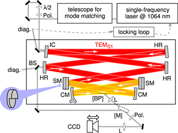
Figure 2. Experimental setup for the high-finesse enhancement cavity with stepped mirrors.  : half-wave plate, Pol.: wire-grid polarizer, IC: input coupler, HR: highly reflective mirror, SM: HR mirror with a stepped surface profile, CM: curved HR mirror, BP: optional Brewster plate, L: lens, BS: beam splitter, diag.: diagnostics, M: optional mirror, CCD: camera on a translation stage.
Download figure:
Standard image High-resolution imageWe seeded the EC with the  mode of a 1064 nm single-frequency laser (Coherent Mephisto S) with a maximum power of 0.5 W, which was linearly polarized in p direction. The seeding laser wavelength was locked to the EC with a Pound–Drever–Hall scheme. The seed was aligned for optimum spatial overlap with the phase-shifted
  mode, which is obtained by offsetting the incoming beam to overlap with one of its lobes.
Near the focus of the EC, we placed a 100 nm thick silicon nitride Brewster plate which allowed us to image the focal region onto a camera placed on a translation stage. To suppress s polarization, which is preferentially reflected off the BP, we used a wire-grid polarizer placed between the BP and the camera. The BP was placed on a magnetic stage, so that the EC could be switched easily between operation with and without the BP.
3. Results
In the first experiment, we operated the EC without the BP and measured the profile of the eigenmode in transmission through a plane, highly reflective mirror, imaging the mirror surface. Figure 3(a) shows the excited mode, with equal scaling for both axes, and figure 3(d) shows a fit of a  intensity profile to the data. From the fit, we obtain a mode size of wx × wy = 2.6 mm × 5.1 mm, corresponding to a beam waist of
  , i.e. Rayleigh ranges of 1105 μm in the horizontal and 296 μm in the vertical direction. Here,
  and
and  were obtained from the complex beam parameter
  , and the wavelength
  assuming a wave-front radius of curvature of 150 mm as given by the focusing mirrors. From the reflected and transmitted powers, we obtain a finesse of 652, corresponding to a round-trip loss of 0.36%. The seed power was enhanced by a factor of 97, at a spatial overlap with the seed of 37%. Theoretically, the spatial overlap can be improved to 82.7% [18] by means of cylindrical lenses and phase masks placed before the EC, which would increase the enhancement to 217. The lock was equally stable as for the operation of the cavity without stepped mirrors at the same position in the stability range. By rotating the wire-grid polarizer placed before the camera by 90°, it was possible to extinguish the signal, confirming that the eigenmode is linearly polarized in p direction.
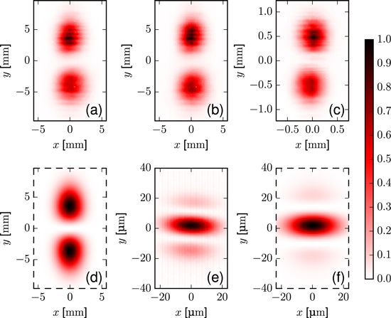
Figure 3. (a) Measured intensity profile on the plane mirror for the cavity without Brewster plate. (b) Measured profile on the plane mirror for the cavity with Brewster plate. (c) Measured profile 19.6 mm before focus, imaged via the Brewster plate. (d) Fit of a  to (a). (e) Measured profile at the focus, imaged via the Brewster plate. (f) Fit of a phase-shifted
  to (e). All images are normalized to the same maximum intensity and the scaling of the y axis fits the scaling of the x axis.
Download figure:
Standard image High-resolution imageIn a second configuration, the BP was introduced, while still imaging the plane mirror. To avoid extreme suppression of p-polarization versus residual s-polarized light when imaging the focus region later, resulting in measurement artifacts, we placed the BP moderately detuned from Brewster's angle. This lead to a drop in power enhancement by a factor of 5.7. However, the cavity mode did not change notably (figure 3(b)). Next, the focal region was imaged via reflection from the BP. Remaining s-polarized light was filtered out by a wire-grid polarizer placed before the camera. First, the plane 19.6 mm before the focus, i.e. well in the far field, was imaged. The intensity profile matched the one measured in transmission through the EC mirror (figure 3(c)). Next, the CCD was moved to image the focal plane. A clear on-axis maximum was obtained, as expected for a  of which one lobe was phase-shifted by approximately half a wavelength (figure 3(e)). To determine the actual focus size, the focal intensity profile of an accordingly phase-shifted
  was fitted, yielding a beam waist of
  =21 μm × 13 μm (figure 3(f)).
Finally, the region near the focus was scanned by translating the camera. This allowed for the observation of the transition from a mode with an on-axis maximum to the intensity profile of a  (figure 4(a)).
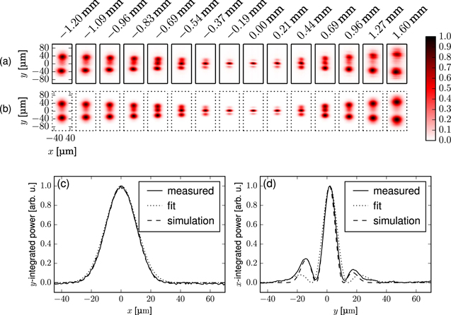
Figure 4. (a) Transverse intensity profiles of the measured resonator mode at different positions near the focus. (b) Comparison with the simulation results. (c) Intensity profile of the measured resonator mode (solid line) in the focus, integrated over the y coordinate. The dotted line shows a fitted  mode with one lobe phase-shifted by π and the dashed line the result of a simulation, accounting for spherical aberrations of the curved mirrors. (d) Intensity profiles, integrated over the x coordinate.
Download figure:
Standard image High-resolution image4. Discussion
The measured mode exhibits some notable differences to a  of which one lobe was phase-shifted by π far from the focus: first, the mode profile in the collimated arm of the EC shows weak modulations in the vertical direction, and the upper lobe appears more intense than the lower one (figure 3(a)). Further inspection reveals that the power contained in the upper lobe is in fact equal to the power contained in the lower (51%/49%), i.e. the power of the lower lobe is just spread over a larger area. We attribute this effect to imperfections in the surface profile of the stepped mirrors. The observed modulations are most probably attributed to the fact that the first stepped mirror was not perfectly imaged onto the second one [9], so that the modification of the mode introduced on the stepped mirror is not completely compensated for.
Another deviation is that the side lobes in the focus are asymmetric and more pronounced than expected from a perfect  with one lobe phase-shifted by π (figures 3(e), (f)). To understand these deviations, we numerically determine the eigenmode of a simulated resonator with the same parameters as in the experiment, using restarted Arnoldi iterations to determine the eigenvectors of a round-trip operator computed on a two-dimensional spatial grid. For this, stepped mirrors with a step height of 2.34 μm, spherical focusing mirrors with a curvature of 300 mm and a resonator length of 3.93 m were assumed, and the curved mirror separation (300.045 mm) and angle of incidence (1.366°) were chosen such that a fit to the
  intensity profile yields a mode size of 2.6 × 5.1 mm, just as in the experiment. The transverse profile was computed at the same positions near the focus where the mode was imaged in the experiment. The simulated profiles (figure 4(b)) show excellent agreement with the experimental data.
When comparing the measured vertical profile in the focus plane with the simulated one, it can be seen that the asymmetry of the side lobes is reproduced (figure 4(d)). This can be attributed to the slight mismatch between the step height and the laser wavelength: the step height of 2.34 μm was chosen to introduce a delay of 2 × 2.34 μm/1040 nm = 4.5 cycles, and thus a phase shift of π, for 1040 nm light. This corresponds to a delay of 2 × 2.34 μm/1064 nm = 4.4 cycles, i.e. a phase shift of  , for the actually used wavelength of 1064 nm. Accordingly, we obtained symmetric side lobes when we repeated the simulation assuming a 1040 nm seed.
The simulation results also reveal the reason why the side lobes are more pronounced than expected (figure 4(d)). Repeating the simulation with a wavelength of 1040 nm and parabolic instead of spherical mirrors, the relative lobe heights of the focal intensity profile of a  mode with one lobe phase-shifted by π can be reproduced. We conclude that the side-lobes are more pronounced due to the spherical aberrations of the curved mirrors.
In the experiment and in the simulations, we observed a second resonance with a similar power enhancement. The spatial profile of the corresponding mode resembles that of a  over the whole cavity length. In contrast to the mode shown in figure 4, the phase difference between the lobes is approximately π in the cavity arm delimited by the stepped mirrors and containing the focus, and 0 in the other arm. The resonant frequencies of the two modes differ by about half a free spectral range, so that each can be locked independently.
4.1. Suitability for TMG
When using broadband pulses, each frequency component of the seed will be enhanced independently by the cavity. For each component, the stepped mirrors will cause a different phase shift  , where
  is the delay given by the step height. Reference [9] shows that the losses for frequency components with a phase shift
  are even lower than the losses for phase shifts around π, the situation demonstrated here. Therefore, good enhancement can be expected even for broadband pulses, when using suitable mirror coatings.
In [9], it is calculated that IAPs around H79 with a photon flux of 108 s−1 can be obtained by TMG, assuming a 156 μm long, 4.6 bar neon gas target placed  before a 15 μm focus of a circulating Gaussian pulse with a FWHM of 17.5 fs, a pulse energy of 33 μJ, a central wavelength of 1040 nm, and a delay of 7 fs, corresponding to a step height of 2.09 μm. In the resonator geometry demonstrated here, a mode size of 2.6 mm × 5.1 mm was measured on the cavity mirrors. Assuming that the transverse intensity profile is identical to the one of a
  mode, it follows that the scheme is power-scalable up to a peak power of 2.6 GW without exceeding a maximum peak intensity of 9 × 10⁹ W cm−2 on the mirrors, which was shown to be low enough to avoid damage in commercially available dielectric mirrors [7]. For 17.5 fs pulses, this corresponds to a pulse energy of 48 μJ, which is even higher than the 33 μJ assumed in [9]. Moreover, the measured focus size of 21 μm × 13 μm = (16.5 μm)2 is comparable to the focus size of (15 μm)2 assumed in [9]. Consequently, the demonstrated geometry would allow the necessary peak intensities in the focus and a sufficient extreme ultraviolet (XUV) generation volume for efficient TMG.
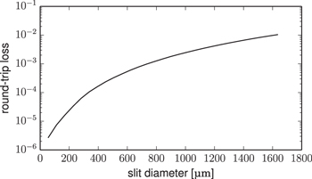
For TMG with the parameters assumed in [9], one beamlet of the generated on-axis XUV radiation can be efficiently output-coupled through a slit opening with a diameter of  in one curved mirror [9]. This corresponds to a diameter of 0.05 × 5.1 mm = 255 μm for the mode size measured here. Figure 5(b) shows that the round-trip loss due to the slit mirror, computed from the simulated mode depicted in figure 4, can be kept on the order of 0.1% for slits as wide as 1000 μm. This would decrease the finesse from 652 to 591 for the input coupler transmission used here.
Figure 5. Round-trip losses of the simulated mode due to a slit mirror, versus slit diameter.
Download figure:
Standard image High-resolution image
5. Conclusions
In conclusion, we produced stepped cavity mirrors with a highly reflective coating, and used these mirrors to set up a high-finesse EC which is compatible with operation at the inner stability edge, showing that such mirrors can be fabricated with sufficient profile quality as well as accuracy in the step height.
If the step height is chosen to cause a delay of half a field cycle, such a resonator does not cause significant WFR and constitutes an efficient broadband output coupling method for XUV radiation generated in an intracavity gas target [11]. In contrast to output coupling using superpositions of higher-order modes in degenerate resonators [13, 18, 19], which requires operation in the middle of the stability range, our scheme permits large modes on the EC mirrors so that mirror damage can be avoided when scaling up the power.
Here, the step is chosen high enough to cause intracavity WFR when operating with pulses, such that the demonstrated resonator geometry can be used to generate IAPs at multi-MHz repetition rates. Such an XUV source will find applications in time-resolved spectroscopy/microscopy and for coincidence measurements. It can also be of use for precision spectroscopy with ultra-broadband XUV frequency combs. Simulations in [9] predict that such a scheme can produce IAPs with a photon flux of 9 × 10⁷ s−1 in a 2% bandwidth around 94 eV, assuming 0.7 μJ, 5-cycle pulses from the seeding laser and state-of-the-art broadband coatings for the EC mirrors. The demonstrated resonator geometry supports a comparable generating volume and peak intensities in the target, so that a similar performance can be expected.
To realize such a source, one has to combine the demonstrated geometry with a phase-stable, high-power and few-cycle pulsed seed [15], broadband cavity mirror coatings [8] and a round-trip carrier-envelope phase shift of zero [20], as well as a slit mirror for output coupling [12, 13]. The mode matching can be improved by shaping the seeding beam profile with cylindrical lenses/mirrors and phase masks, and/or by using an input coupler with a half-sided highly-reflective coating.
Acknowledgments
This research was supported by the Fraunhofer Society/Max-Planck Society cooperation 'MEGAS'. We thank Johannes Weitenberg for useful discussions.