
Abstract
We propose a simple and compact method for implementing an in-fiber Mach–Zehnder interferometer, which is constructed with two optical paths, propagating through the core and the ring-shaped silica cladding modes in the double-cladding fibers. Strong cladding-mode resonance across the thin inner cladding is used to excite the cladding modes. The measured spectra fringe presents high-contrast interference from cascading a pair of well-overlapped resonant spectra dips. In combination with the nonlinear polarization rotation (NPR) technique, switchable and tunable multi-channel laser outputs are experimentally demonstrated with a fluctuation of less than 0.1 dB.
Export citation and abstract BibTeX RIS
1. Introduction
Multiwavelength erbium-doped fiber lasers (MW-EDFLs) are able to provide simultaneously multiple channels with tunability of the lasing wavelength, the wavelength spacing and the number of channels. Such features have attracted great interest for many applications, such as wavelength division multiplexed (WDM) systems, fiber sensors and sensing network, precise spectroscopy, etc. The functionality and flexibility was enhanced through several approaches, such as a Fabry–Perot filter [1], cascaded long-period fiber gratings (LPFGs) [2], a Sagnac high-birefringence loop filter [3], a superimposed chirped-fiber Bragg grating [4], etc. In-fiber interferometers have been studied widely. These periodical filters have been inserted into the laser cavity acting as the comb function but with polarization asymmetry due to the exposure fabrication of the fiber grating [5]. Recently, several approaches regarding the in-fiber Mach–Zehnder interferometer (MZI) have been experimentally investigated based on LPG and a photonic crystal fiber (PCF). Two interference arms are integrated into a single fiber forming the in-fiber interferometer [6–11]. Compared with the conventional MZIs, the in-fiber MZI has a singular fiber structure, and the arm difference can be easily controlled. Additionally, recent attempts to exploit the intrinsic optical-path difference between the fundamental core and cladding modes have been reported by using a micro air cavity [6] or air holes collapsed in a single piece of PCF [7] or through deliberately forming the lateral offset during fusion splicing the PCF or multi-mode fibers [9].
In this paper, a novel and simple in-fiber MZI serving as the comb filter in the cavity is proposed. The MZI demonstrated here is constructed by simply splicing a standard single mode fiber (SMF) sandwiched inside two sections of double-cladding fiber (DCF), which has an inner cladding layer between the core and the conventional cladding layers of a fiber [12]. The inner cladding has lower refractive index than the core and out cladding layers, which lead to the power being transferred to the outer cladding and supporting the cladding modes at phase-matching wavelengths. As a result, the core mode presents a band-rejection filter spectrum [13]. We show the filter spectrum through the all-fiber structure of SMF–DCF–SMF and the spectra fringe from cascading a pair of well-separated resonant spectra dips. Then we sandwich the MZI in the ring cavity acting as a comb filter. In combination with the nonlinear polarization rotation (NPR) technique to alleviate mode competition [1, 14], we achieve switchable and tunable multi-channel laser outputs, which are experimentally demonstrated with a fluctuation of less than 0.1 dB. The wavelength space and numbers can be controlled by the comb filtering of the in-fiber interference.
2. Principle of the in-fiber MZI
Figure 1(a) shows the schematic diagram of an in-fiber MZI by simply sandwiching a standard SMF inside two sections of multi-cladding special fiber. Through the conventional modified chemical vapor deposition (MCVD) technique, the core and outer cladding layers of DCF are made of pure silica and the inner cladding is made of fluorine-doped silica. The core and outer cladding layers have the same refractive index, which is a little higher than that of the inner cladding (n1 = n3 = 1.4560, n2 = 1.4536) and the cross section and the diameter geometry (a = 4.6 µm, b = 13.0 µm, c = 63.0 µm) as shown in figure 1(b). By using an optical fiber analyzer (EXFO NR9200), the refractive index profile of DCF was measured as shown in figure 1(c). The core and outer cladding had equal refractive index and the refractive index difference is 0.2%.
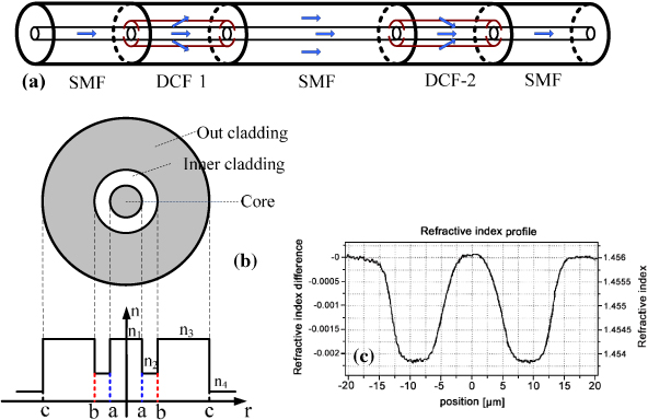
Figure 1. (a) Schematics of the in-fiber MZ interferometer based on splicing DCFs and SMFs and (b) cross-section view and (c) refractive index profile of the DCFs.
Download figure:
Standard imageBased on the mode analysis of the depressed cladding structure [14], the double-cladding fiber is a typical leaky waveguide, i.e. the core mode wave will tunnel out through the inner cladding layer at phase-matching wavelengths. To understand the dynamics of light evolution in DCF, we expand the fundamental mode φLP01 of SMF as the sum of ϕLP0n modes of DCF, φLP01(r,z) = ∑ncc1nϕLP0n(r)exp(−jβnz) [15]. βn is the propagation constant of ϕLP0n and cc1n is the coupling coefficient between the SMF φLP01 mode and the DC fiber modes ϕLP0n. These excited modes ϕLP0n propagate along the double-cladding fiber and beat with each other due to their different propagation constants. Using the measured parameters from DCF investigated here, we calculate the coupling coefficient cc1n of the dominant mode fields ϕLP0n of DCF and the field distribution. It is noticed that the lower ten modes accounted for most of the optical energy, especially the dominant modes ϕLP05 and ϕLP06 as shown in figure 2(a). The sum of these two modes has 92% energy of the input SMF φLP01. Thus the transmission spectrum of the DC fiber can be explained by a dual-mode interference process. This dual-mode interference will cause optical power exchange between the core and the outer cladding modes.
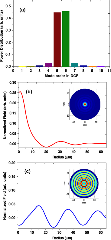
Figure 2. (a) Power distribution of excited modes in DCF. (b) Field distribution of the sum of LP05 and LP06 modes at the input point and (c) at the beat length point.
Download figure:
Standard imageConsequently simplifying the propagation analysis, the superposition of the modes ϕLP05 and ϕLP06 can be used to approximate the real energy distribution. At the input point of DCF, due to no phase difference between LP05 and LP06 modes, most of input optical energy is the sum of the dominant two modes and restricted in-fiber core. After a propagation distance of LB = π/(β05 − β06), namely a beat length, the phase difference between the two modes becomes π and total energy is coupled to the fiber cladding. The field distribution at the input and the beat length, are shown figures 2(b) and (c), respectively.
3. Experiment setup and results discussion
We prepared an in-fiber MZI using DCFs, whose core and inner cladding are made of pure silica and fluorine-doped silica deposited with the conventional modified chemical vapor deposition (MCVD) method. The coats of both DCF and SMF are removed to ensure cladding modes can propagate in-fiber.
After fusion splicing a proper length of SMF between two DCFs, an in-fiber Mach–Zehnder interferometer is obtained. The input fundamental mode guided through the SMF core is coupled to several cladding modes and separated into two paths as it enters into the first DCF; one passes through the fiber core while the other propagates as a ring-shaped cladding mode in the outer cladding layer. Two separated light waves experience different effective indices in the middle segment of SMF. The cladding modes are coupled back to the core mode in the second DCF and interfere with the core mode.
The interference spectrum is cause by a phase difference between the dominant modes traveling different optical paths in the DCF–SMF–DCF structures. At a certain wavelength, output power reaches the maximum owing to the cancellation of two interference paths when the phase difference between them equals the odd times of π; the output power reaches the minimum when the phase difference between two interference paths equals the even times of π. The total phase difference at the output of in-fiber MZI includes the phase difference caused by both the DCFs and the SMF between them. Usually the SMF is much longer than the DCF; therefore the total phase difference in interference is mainly cause by the SMF and can be estimated by

where  and
and  are the effective refractive indices of core and cladding modes, respectively. In order to maximize the contrast of the interference spectrum, the coupling ratios of two DCFs are required to be 3 dB, which can be achieved by choosing the length of DCFs to be the odd times of the half beat length LB according to the coupled mode theory. The free spectrum range (FSR) can be estimated by using
The lengths of two DCFs are approximately 48 mm to obtain the identical resonant spectrum dips and the measured spectra are depicted in figure 3(a). The subtle mismatch between two resonant spectra stems from the micro-scale length error of DCFs used under current experimental conditions, which can be alleviated by improving the fiber cutting and splicing technique. The FSR of interference is measured to be about 4.6 nm, in good agreement with the numerical results. The light power coupled to the inner cladding from the fiber core leads to a 5 dB drop in the transmission spectrum at the resonant wavelength. The measured interference spectrum is shown in figure 3(b). It also shows good coincidence with the theoretical transmission spectrum by simulating 48 mm DCFs and 16 cm SMF of in-fiber MZI in figure 3(c). Besides LP05, LP06 there are still small modes stimulated in our practical operation which may cause the small fluctuation, it also explains the difference between measurement and theory. But this fluctuation does not affect the resonant wavelength of our interferometer.
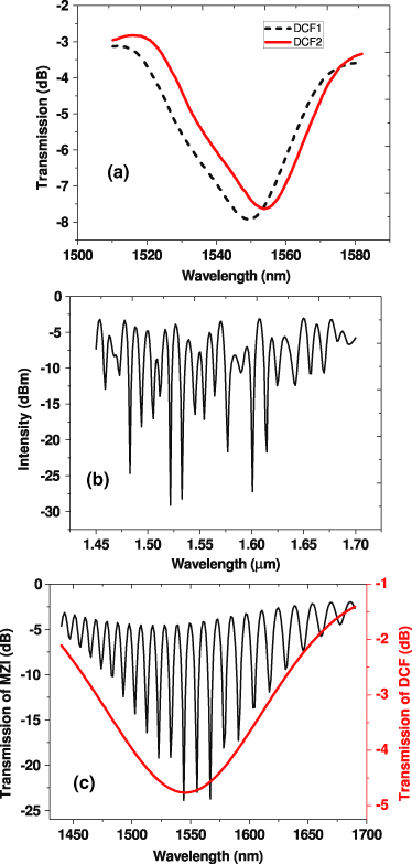
Figure 3. (a) Measured transmission spectrum of the DCFs, (b) measured interference spectrum of the in-fiber MZI, (c) numerical result of the transmission spectrum of DCF and in-fiber MZI.
Download figure:
Standard imageThe switchable erbium-doped fiber laser (EDFL) is configured as shown in figure 4. We use the same nonlinear polarization rotation (NPR) technique as in recent reports [1, 14] to alleviate mode competition. It consists of an in-fiber MZI as the comb filter, a 980 nm pump source, 980 nm/1550 nm WDM and an erbium-doped fiber, a standard SMF, two polarization controllers (PCs), a polarization dependent isolator (PDI), which serves both as an optical isolator and a polarizer, and a 95:5 coupler through which 5% of the light goes to the optical spectrum analyzer (OSA) while 95% continues to cycle in the laser cavity.

Figure 4. Schematic diagram of the multiwavelength fiber laser.
Download figure:
Standard imageThe two PCs, PDI and SMF control the evolution of mode polarization inside the laser cavity, in which the NPR effect induces intensity dependent loss (IDL). The IDL is not the same for different wavelengths, which can be used to alleviate the mode competition and also to choose the oscillation mode that we need. The extra SMF is used to increase the Kerr nonlinearity. By adjusting PCs, a different status of output laser is observed. We achieve the tunable single wavelength output as shown in figure 5(a), the dual wavelength output in figure 5(b) and the triple wavelength output in figure 5(c), respectively. The expected oscillation wavelengths correspond to the transmission spectrum of the MZI employed as 1546.2, 1550.8, 1556.4, 1561.0, and 1565.6 nm. The signal to noise ratios (SNRs) of all channel outputs are nearly 30 dB and the fluctuation is less than 0.1 dB. The stable multiwavelength laser output is dependent on the cavity loss induced by the NPR effect and different modes can be obtained by precisely adjusting PCs.
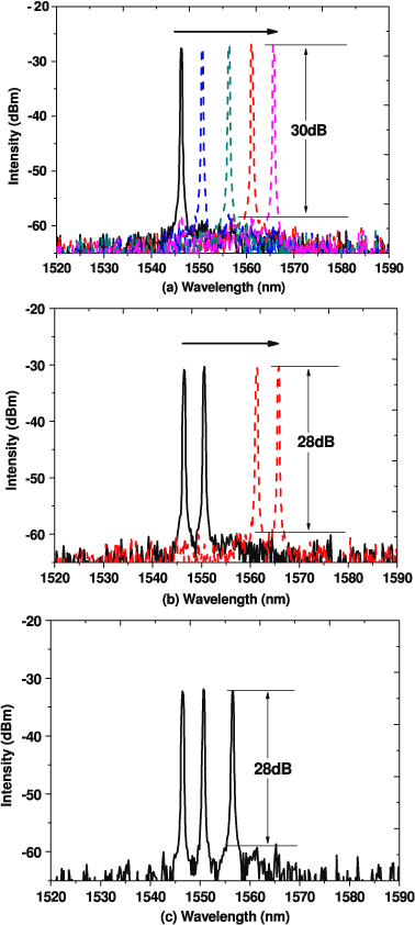
Figure 5. Different laser output channels: (a) single wavelength; (b) dual wavelengths; (c) triple wavelengths.
Download figure:
Standard image4. Conclusion
In conclusion, we demonstrate a novel and simple technique to generate a stable multiwavelength laser. The demonstrated spectra fringe presents high contrast from cascading a pair of well-overlapped resonant spectra dips. In combination with the nonlinear polarization rotation (NPR) technique, switchable and tunable multi-channel laser outputs are experimentally demonstrated with a fluctuation of less than 0.1 dB.
Acknowledgments
This work is supported in part by the National Natural Science Foundation of China (60978004, 60937003, and 61132004), Shanghai Municipal Education Commission (10YZ14), the Shuguang Program (10SG38), the Rising-Star Program (10QA1402600), SSTCP (11511502501-2), and the Leading Academic Discipline Project (S30108).