

Abstract
Osteochondral (OC) matrix design poses a significant engineering challenge due to the complexity involved with bone-cartilage interfaces. To better facilitate the regeneration of OC tissue, we developed and evaluated a biodegradable matrix with uniquely arranged bone and cartilage supporting phases: a poly(lactic-co-glycolic) acid (PLGA) template structure with a porosity gradient along its longitudinal axis uniquely integrated with hyaluronic acid hydrogel. Micro-CT scanning and imaging confirmed the formation of an inverse gradient matrix. Hydroxyapatite was added to the PLGA template which was then plasma-treated to increase hydrophilicity and growth factor affinity. An osteogenic growth factor (bone morphogenetic protein 2; BMP-2) was loaded onto the template scaffold via adsorption, while a chondrogenic growth factor (transforming growth factor beta 1; TGF-β1) was incorporated into the hydrogel phase. Confocal microscopy of the growth factor loaded matrix confirmed the spatial distribution of the two growth factors, with chondrogenic factor confined to the cartilaginous portion and osteogenic factor present throughout the scaffold. We observed spatial differentiation of human mesenchymal stem cells (hMSCs) into cartilage and bone cells in the scaffolds in vitro: cartilaginous regions were marked by increased glycosaminoglycan production, and osteogenesis was seen throughout the graft by alizarin red staining. In a dose-dependent study of BMP-2, hMSC pellet cultures with TGF-β1 and BMP-2 showed synergistic effects on chondrogenesis. These results indicate that development of an inverse gradient matrix can spatially distribute two different growth factors to facilitate chondrogenesis and osteogenesis along different portions of a scaffold, which are key steps needed for formation of an OC interface.
Export citation and abstract BibTeX RIS
1. Introduction
Repair of osteochondral (OC) defects caused by osteoarthritis (OA) is a major clinical challenge. OA, a degenerative joint disease, ranks 11th in global disability contribution, affecting more than 66 million people in the US and costing about $303 billion in medical expenditures annually [1–4]. Microfracture and the use of autografts or allografts are some of the major clinical modalities currently adopted to treat OC defects [5–7], but neither are completely effective. Microfracture is often reported to form fibrocartilage or hypertrophic cartilage over time, which leads to mechanically inferior tissue and further deterioration [8–10]. Autografts suffer from limited availability and donor-site morbidity, and allografts present risk of disease transmission and lack of integration with the host tissue [11, 12].
Recently, tissue engineering (TE) has emerged as an alternative strategy for OC tissue repair and regeneration. This approach involves natural/synthetic biomaterials in association with bone/cartilage-forming cells and/or growth factors. There has been tremendous progress in the design of biomaterial structures that are optimally porous and biomechanically compatible for bone formation [13–16]. Similarly, advances have been made with the design and assessment of various hydrogels, including hyaluronic acid, fibrin, and synthetic hydrogels for mesenchymal stem cell (MSC) chondrogenesis and cartilage engineering [17–21]. While much has been achieved in terms of the biomaterials, cells, and growth factors for bone and cartilage TE, challenges in regeneration of bone-cartilage interface remain [3, 4, 12, 17].
The major challenge in OC TE lies in recapitulating distinct phases of native tissue, bone, cartilage, and their interface, in one graft [3, 22, 23]. In the past, biphasic grafts were developed with distinct phases to support either bone or cartilage growth as separate tissue types [24–27]. Although, some of these strategies partially supported cartilage and bone regeneration in their specified layers, they failed to establish an interface similar to that of native OC tissue [28, 29]. Since OC tissue is uniquely structured, with a mineralized subchondral layer followed by articular cartilage layer, OC TE requires the development of unique matrices, which not only support regeneration of the individual tissue layers but also help to establish a proper bone-cartilage interface [30]. Therefore, to recapitulate native zonal structures and promote integration of the bone and cartilage phases, gradient scaffolds that feature a smooth transition between the bone and cartilage layers have been developed. These structures were studied for osteogenesis and chondrogenesis in different parts of the scaffold in vitro and OC tissue development in OC defect models [3, 23, 31–34].
Previously, we reported the development of a unique matrix platform with continuous structure from one end to the other but with variable pore structure [15, 35, 36]. Additionally, through the development of co-differentiation media, we demonstrated that our OC gradient matrix scaffold is capable of both chondrogenesis as well as osteogenesis in vitro [17]. However, beyond simply developing a matrix that resembles OC tissue, it is imperative that the OC implants also include signaling molecules to induce osteochondrogenesis [37]. This is achieved by incorporating growth factors that promote either bone or cartilage differentiation in the respective layers. The efforts in this direction have used transforming growth factor beta 1 or 3 (TGF-β1 or TGF-β3) as a chondrogenic factor and bone morphogenetic protein 2 (BMP-2) as an osteogenic factor in conjunction with OC scaffolds [17, 38]. Furthermore, growth factor synergy studies have also found that TGF-β1 in unison with BMP-2 can be used to aid MSC chondrogenesis [39, 40]. Some current approaches introduce growth factors into OC scaffolds, ranging from physical encapsulation to chemical tethering, allowing for controlled release [33, 41–43]. However, in addition to controlling release kinetics of growth factors in defect areas, it is also necessary to control growth factor distribution in the scaffold. Therefore, it is warranted to design OC scaffolds to enable control on spatial distribution of TGF-β1 and BMP-2 along the scaffold length to support zonal structure and bone-cartilage interface formation.
Here we report a gradient scaffold system developed using biodegradable polymer and gel biomaterials with spatial growth factor loading of BMP-2 and TGF-β1 for OC TE.
2. Materials and methods
2.1. Gradient template fabrication
A gradient template structure was fabricated using thermal sintering and porogen leaching technique developed in our lab [35, 36]. In this method, poly-(85-lactide-co-15-glycolide) (PLGA 85/15, Evonik Industries) microspheres were combined with NaCl porogen to form a 3D, porous structure. To form the microspheres, PLGA 85/15 was dissolved in methylene chloride at a 1:6 ratio and poured into a beaker of 1% polyvinyl alcohol solution spinning at 250 rpm to form microspheres via an oil-in-water emulsion process. The PLGA microspheres were then vacuum filtered to dry, and sieved to obtain spheres in the size range of 355–425 µm. The collected microspheres were then mixed with NaCl (size range 106–212 µm) at different ratios (0%, 5%, 10%, 20%, and 40% NaCl by weight). These different mixtures were sequentially layered upon each other within a metal mold, generating a NaCl porogen gradient through the scaffold. The mold was then thermally sintered at 100 °C for 1 h to form scaffolds of 5 mm diameter and 10 mm length. Once the mold reached room temperature, the structure was collected and leached for porogen removal by soaking samples in deionized water for 2 h [15, 35]. Template structures without porogen and with 30% porogen evenly distributed throughout the structure were also prepared using the same method.
2.2. Inverse gradient matrix fabrication
To create an inverse gradient matrix, the available pore space of the developed template scaffold was filled with a hyaluronic acid hydrogel (Glycosil, Advanced Biomatrix). In short, the hydrogel was mixed with polyethylene glycol (PEG) crosslinker (Extralink, Advanced Biomatrix) in a 2:1 ratio, and immediately pipetted onto the more porous end (distal end) of the scaffold, as previously reported [17]. Prior to completely crosslinking, the gel infiltrates downward, filling the scaffold's available pore space. Using this method, an inversely graded matrix is developed that has a distal cartilaginous region and a proximal (less porous) osseous region.
To increase regenerative potential of both cartilage and bone phases, growth factors were incorporated into the inverse gradient matrix. The gel phase was formed with thiol-modified gel and crosslinker to increase the gel phase affinity to bind with external factors. For the template matrix, PLGA polymer was combined with hydroxyapatite (HAp) nanoparticles, a strong promoter of growth factor adsorption [44, 45]. Just as before, PLGA and HAp were dissolved in methylene chloride at a 1:4 ratio to form PLGA:HAp composite microspheres [46]. The composite microspheres were used to form template structures as well as the inverse gradient matrices using the methods described above. The completed PLGA:HAp scaffolds were subjected to x-ray energy dispersive spectroscopy (EDS) analysis to confirm HAp nanoparticle distribution. The scaffolds were sputter coated with gold/palladium for 3 min (E5100, Polaron) and examined using a scanning electron microscope (Nova NanoSEM 450, FEI). EDS was performed using Oxford Aztec Energy Microanalysis System with X-Max Silicon Drift Detector using an accelerating voltage of 15 kV.
2.3. Scaffold characterization via micro-computed tomography (Micro-CT)
Template structures were imaged using cone beam micro-focus x-ray computed tomography (µCT40, Scanco Medical AG, Bassersdorf, Switzerland) to render 3D models for direct quantitation of the porosity gradient [15]. Serial tomographic images were acquired at 45 kV and 177 µA, collecting 2000 projections per rotation at a 300 ms integration time. 3D, 16-bit grayscale images were reconstructed using standard convolution back-projection algorithms with Shepp and Logan filtering, and rendered within a 12.3 mm field of view at a discrete density of 4629 630 voxels mm−3 (isometric 6 µm voxels). Segmentation of solid scaffold from open porosity was performed in conjunction with a constrained Gaussian filter to reduce noise, applying a threshold of −100 Hounsfield units (water = 0, air = −1000). Scaffold pore volume was measured directly in a plane transverse to the cylindrical axis at every 6 µm interval, producing a gradient map of pore volume along the length of the scaffold.
To verify infiltration of hyaluronic acid gel into the inverse gradient matrix provided by the PLGA, and to quantify this inverse gradient of the two discrete phases, the same micro-CT imaging technique was used as described above. Since the two constituent phases attenuate x-ray to a low degree and without differentiation, a contrast agent was added to the gel phase in a 1:1 ratio (Histopaque, Sigma-Aldrich) to clearly distinguish the two discrete phases of hyaluronic acid gel and PLGA [47, 48].
2.4. Oxygen plasma treatment of PLGA:HAp scaffold
To increase growth factor binding, the scaffolds were treated with oxygen plasma. Briefly, PLGA:HAp gradient template structures were placed in the chamber of a CUTE-1MP/R Plasma Processing System (FEMTO Science Inc.) and were individually treated for 5 min at 100 W power, 5 torr processing pressure, and 0.5 torr base pressure.
To characterize the effect of the oxygen plasma treatment, PLGA:HAp composite films were treated with oxygen plasma and then subjected to contact angle measurements. In brief, PLGA and HAp was dissolved in methylene chloride, as described above, and cast into a plastic 100 × 15 mm culture dish covered with Bytec paper (Saint Gobain). The dissolved polymer was poured onto the dish at 4 °C. The composite film was left overnight in 4 °C and further dried in a desiccator. After 24–48 h, 18 mm diameter pieces were bored from the films and were plasma-treated using the same parameters described above. Finally, using a goniometer (Rame Heart, Model 100), the static contact angle measurement was performed for untreated as well as plasma-treated films (n = 5).
2.5. Model protein loading and visualization
To test and model growth factor loading, the PLGA:HAp template scaffold and the crosslinked hyaluronic acid hydrogel were loaded with bovine serum albumin (BSA) fluorescently tagged with either Alexa Fluor 647 or Alexa Fluor 555, respectively (ThermoFisher Scientific). For the template structure, 80 µl of the reconstituted BSA with Alexa Fluor 647 (1 mg ml−1) was added directly onto the scaffold and was allowed to dry overnight. The next day, 20 µl of BSA with Alexa Fluor 555 (1 mg ml−1) was added to 33.3 µl of hyaluronic acid gel prior to addition of PEG crosslinker (2 hyaluronic acid:1 PEG), and the resulting solution was pipetted onto the distal end of the PLGA:HAp template that was previously loaded with BSA with Alexa Fluor 647. Once the gel was crosslinked, the distal and proximal ends of the BSA-loaded matrix were visualized using a Zeiss Confocor 2 Confocal Microscope for model protein distribution.
2.6. In vitro evaluation of growth factor-loaded OC scaffolds
Inverse gradient matrices with PLGA:HAp composite templates infused with hyaluronic acid were selected for in vitro evaluation. The template scaffold was loaded with BMP-2 by loading 1 ml of BMP-2 solution (2.5 µg ml−1) to the PLGA:HAp template and allowing it to dry and adsorb overnight. The scaffolds were cut into two halves along the transverse plane and labeled as either distal (more porous end of the graded template) or proximal ends (less porous end of the graded template).
For the hydrogel portion of the matrix, hyaluronic acid gel containing 1.25 µg of TGF- β1 was prepared by combining 20 µl of TGF-β1 solution (62.5 µgml−1) with 33.3 µl of hyaluronic acid and 16.7 µl of PEG crosslinker (2:1 ratio, as described in section 2.2). Further, the gel was mixed with 500 000 CD271+ bone marrow-derived human MSCs (hMSCs; passage 5). hMSCs were isolated by concentrating freshly isolated human bone marrow aspirate with proper ethical controls and consent obtained by Lonza (Lonza, Cat #. 1M-125) with the automated Magellan system (Arteriocyte Medical Systems) to obtain concentrated bone marrow aspirate (cBMA) as previously described [49, 50]. Then, MSCs were isolated from the cBMA via magnetic-activated cell sorting for cells expressing the MSC marker, CD271, and cultured until passage 5 [35]. CD271 was used as a marker for MSCs due to its specificity to isolate homogeneous MSC population without going through plastic culture [51, 52]. The flow cytometry cell sorting data and tri-lineage differentiation experiments were conducted as per the established protocols [17]. Afterwards, based on the micro-CT data, the appropriate amount of gel containing hMSCs and TGF-β1 was added to both the distal and proximal portions of the cut scaffold to fill the available pore space (53.7% and 46.3% of the total mixture, respectively). Once crosslinked, distal portions of the scaffolds were cultured in the co-differentiation media, previously established by our group [17]. The proximal portions were treated with the same co-differentiation media with the addition of 100 000 hMSCs in the suspension to mimic the infiltration of bone marrow stromal cells that would occur post-implantation due to its proximity to bone marrow.
After 21 days, both the distal and proximal portions of the scaffolds were assessed for chondrogenesis through glycosaminoglycan (GAG) quantification (n = 3) via dimethyl methylene blue (DMMB) assay [35, 49, 53], and osteogenesis through mineral formation (n = 3) using the alizarin red assay [54]. Briefly, for GAG quantification, samples were removed from culture, digested in a proteinase K solution (1 mg ml−1) for 16 h at 56 °C. Afterwards, 50 µl of the resulting lysate was combined with 200 µl of DMMB solution (16 µg ml−1, pH 3) and absorbance was measured at 520 nm wavelength. For quantifying total calcium deposition, samples were removed from culture, washed with PBS, and fixed with 70% ethanol. The fixed samples were then stained with 40 mM alizarin red solution (pH 4.23) for 10 min. at room temperature. The samples were then washed thoroughly to remove excess dye and the stain was solubilized using a 10% cetylpyridinium chloride solution for 15 min. The solubilized dye was then measured for absorbance at 562 nm wavelength.
2.7. BMP-2-treated chondrogenic cultures
To determine whether BMP-2 might deter chondrogenesis or promote osteogenesis in the distal (cartilaginous) region of the matrix, chondrogenic cell pellets were made and treated with increasing concentrations of BMP-2. Briefly, 250 000 hMSCs, passage 5, were placed in microcentrifuge tubes to form a pellet and cultured with one of five media combinations. The control media was chondrogenic media (serum free, high glucose, basal media (Gibco) supplemented with ITS+, 100 μl ml−1 sodium pyruvate, 40 μg ml−1 L-proline, 50 μg ml−1 ascorbate-2-phosphate, 10−7 M dexamethasone, and 10 ng ml−1 TGF-β1). The remaining four groups were chondrogenic media supplemented with 25, 50, 100, or 250 ng ml−1 of BMP-2.
BMP-2 in the culture media was refreshed once every 3 days when the media was changed. After 21 days of culture, the cell pellets were assessed for both their chondrogenesis via DMMB assay and osteogenesis using alizarin red staining. The scaffolds were also subjected to whole-mount immunofluorescence analysis using primary antibodies (Abcam, Cambridge, MA) to image chondrogenic (Collagen Type II (1:100) and Sox9 (1:50)) as well as osteogenic (Collagen I (1:100) and RUNX2 (1:50)) marker protein expression. Deoxyribonucleic acid (DNA) content was quantified using the PicoGreen double stranded DNA (DNA) assay and used to normalize GAG and calcium quantification.
2.8. Statistical methods
Statistical analyses were performed using an unpaired t-test for all studies that compared the distal to the proximal end. The analyses to determine the effect of BMP-2 on chondrogenesis used a one-way analysis of variance with Tukey's post-test. Quantitative data were reported as means ± the standard deviation, and a significance level of p < 0.05 was used in all statistical tests performed.
3. Results
3.1. Design of a porosity gradient template structure
We employed thermal sintering and porogen leaching scaffold fabrication method and varied the amount of porogen along the scaffold length. The resulting scaffolds were imaged using micro-CT to qualitatively and quantitatively characterize the variation in pore volume with respect to the amount of porogen added (figure 1). PLGA template without any added porogen presented a relatively even distribution of pores that fluctuated around 40% pore volume with respect to the longitudinal axis of the scaffold (figure 1(A)). PLGA template with an even amount of porogen (30% by mass) also showed relatively uniform porosity throughout the scaffold, around 45% pore volume (figure 1(B)). However, varying porogen content along the longitudinal axis resulted in a template structure with pore volume that gradually increased from approximately 35% to 65% (figure 1(C)). The gradient nature of the template structure is also clearly visible in the rendered image, where the bottom of the template (without any porogen) is densely packed with PLGA while the top (40% porogen) is relatively open with less PLGA. The increase in pore volume with respect to scaffold height corresponds with increasing amounts of porogen added to the scaffold, which ranged from 0% to 40% by weight.
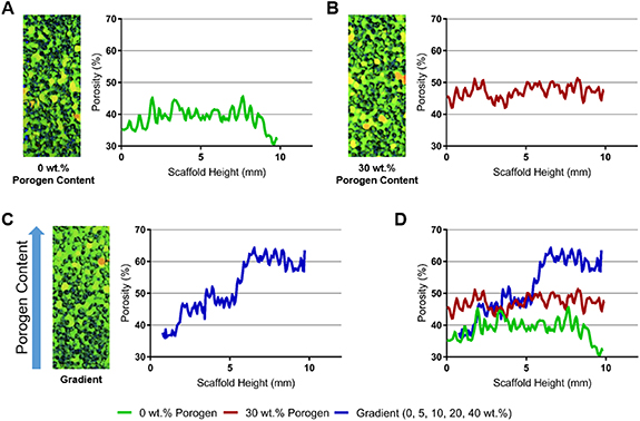
Figure 1. Micro-CT scans and pore volume quantifications of the PLGA template structures. (A) Structure without the addition of porogen, (B) structure with 30% of porogen (by weight) throughout the scaffold length, (C) structure formed by layering polymer and porogen batches, and (D) comparison of the structure pore volume along the scaffold length after porogen leaching.
Download figure:
Standard image High-resolution image3.2. Formation of an inverse gradient matrix
While the PLGA template structure is suitable for bone regeneration, an OC matrix requires bone and cartilage supporting regions in a single matrix system. To achieve this, an inverse gradient matrix was formed by infusing the gradient PLGA template with hyaluronic acid gel. The gel phase served as the secondary phase, which is known to support MSC chondrogenesis in vitro and in vivo [17, 55]. Micro-CT was performed to confirm the creation of an inverse gradient matrix. As seen in figure 2(A), moving from the top to the bottom of the scaffold (0–10 mm), hydrogel content decreased from 50% to 35%. In contrast, the PLGA content increased from 50% to 65%. Representative slices at 0 mm, 4.04 mm, and 8.10 mm clearly allowed visualization of the inverse relationship between the hydrogel and PLGA content along the scaffold length (figure 2(B)). The hydrogel (shown as black) is relatively prevalent in the 0 mm section, while the PLGA (shown as green) is much more abundant in the 8.10 mm section. These results show that the gel phase of the graft (hyaluronic acid) was able to infiltrate the PLGA gradient template to establish an inverse gradient matrix.
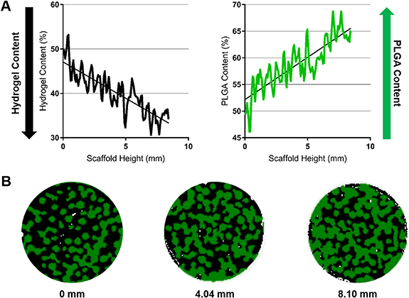
Figure 2. Hyaluronic acid gel and PLGA material quantification in the inverse gradient matrix using Micro-CT. (A) Gel and PLGA contents in the inverse gradient matrix showing that the gel content decreases from top to bottom while the PLGA content increases. (B) Representative sections taken at 0 mm, 4.04 mm, and 8.10 mm depths (from top to bottom) depict the gradual decrease in hydrogel (black) and increase in PLGA (green) seen from the distal cartilage and proximal bone ends.
Download figure:
Standard image High-resolution image3.3. Spatial distribution of model proteins in the inverse gradient matrix
The presence of HAp in the PLGA:HAp composite microsphere scaffold was analyzed via EDS analysis. As shown in figure 3, composite microspheres showed presence of HAp on the surface of the microspheres, determined by the co-localization of calcium and phosphorus atoms. The HAp nanoparticles formed clusters distributed sparsely along the surface of the PLGA microspheres. The Ca:P ratio was also found to be relatively close to that of HAp (1.57 vs 1.67) which indicates minimal change in chemical composition of HAp, although the results are only semi-quantitative. The PLGA:HAp composites were subjected for plasma treatment, as described in section 2.4. For this purpose, PLGA:HAp films were cast and plasma-treated in order to provide a flat surface for the contact angle measurements (as described in section 2.4). The untreated PLGA films showed a contact angle of 70.16 ± 3.41°, while the treated samples exhibited significantly lower contact angle of 48.72 ± 2.14° (figure 3). This indicates a significant increase in hydrophilicity of the template scaffold through oxygen plasma treatment.

Figure 3. Hydroxyapatite loading and oxygen plasma treatment to increase growth factor affinity. (A) SEM and EDS of PLGA:HAp composite scaffold. SEM shows hydroxyapatite distribution on the scaffold surface, while EDS imaging show the atoms that are present in the sample. EDS spectra present peaks corresponding to Ca, P, O, C (from PLGA:HAp sample) and Au, Pd (from the sputter coating), and the atomic ratios taken from the spectra are shown the table. (B) PLGA:HAp contact angle via static contact angle measurement. Oxygen plasma treated PLGA:HAp films show a significant decrease in contact angle (increase in hydrophilicity) (n = 5). The asterisk depicts significance at P < 0.05.
Download figure:
Standard image High-resolution imageFluorescently labeled model proteins were used to visualize growth factor distribution in the inverse gradient matrix. BSA tagged with Alexa Fluor 647 was used to model osteogenic factor adsorption to the plasma-treated PLGA template structure, and BSA tagged with Alexa Fluor 555 incorporated into the hydrogel was employed to track chondrogenic factor distribution in the gel phase. The template structure and the hydrogel with model proteins were integrated to form the inverse gradient matrix (figure 4). The osteogenic model protein was labeled with red fluorescence while chondrogenic model protein was labeled with green fluorescence. The distal, cartilaginous region of the matrix with an abundance of hyaluronic acid gel showed the presence of both osteogenic and chondrogenic model proteins. The proximal, osseous region of the matrix only showed the presence of osteogenic model protein. Since the amounts of each model protein in PLGA and gel phase is directly proportional to the amounts of each phase present, gradient matrix formation itself can result in spatial distribution of the respective growth factors.
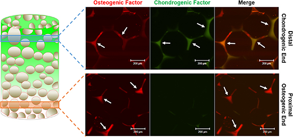
Figure 4. Visualization of protein loading in the inverse gradient matrix. Fluorescently conjugated model BSA proteins adsorbed on plasma-treated PLGA:HAp microsphere scaffolds and mixed into the hyaluronic acid gel were imaged by confocal microscopy. Red depicts the osteogenic model protein and green depicts the chondrogenic model protein in the distal (chondrogenic) end as well as the proximal (osteogenic) end. As depicted by the arrows, osteogenic model protein presence is seen both in the distal (chondrogenic) and proximal (osteogenic) ends with increased levels in the proximal (osteogenic) end, while the chondrogenic model protein presence is limited to the distal (chondrogenic) end.
Download figure:
Standard image High-resolution image3.4. Growth factor-induced chondrogenesis and osteogenesis
To assess growth factor-induced effects of the developed scaffold, inverse gradient matrices loaded with BMP-2 and TGF-β1 were studied in vitro. The BMP-2 loaded matrices were cut in half, loaded with hMSCs and TGF-β1 containing hydrogel, and cultured for 21 days in OC co-differentiation media (figure 5(A)). The proximal half of the cut scaffold was also cultured with cells in suspension to model the infiltration of bone marrow cells post-implantation.
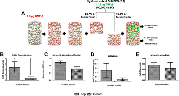
Figure 5. In vitro study design and culture of the inverse gradient matrices. (A) Oxygen plasma-treated PLGA:HAp scaffold with surface-absorbed BMP-2 is cut in half and infiltrated with cross-linked hyaluronic acid gel containing TGF-β1 and hMSCs. The distal (top) and proximal (bottom) portions are cultured separately in co-differentiation media [17]. Additional hMSCs are added to media in suspension to the distal portion to simulate in vivo implantation. After 21 days of side-by-side culture, GAG quantification for the top and bottom half of the matrices is shown in (B), and mineralization is shown in (C). The normalized GAG and mineralization amounts with respect to the amount of DNA are shown in (D) and (E), respectively. The asterisk depicts significance at P < 0.05.
Download figure:
Standard image High-resolution imageAfter the 21 days of culture, the top (distal; cartilaginous) portion of the graft presented significantly higher GAG content than the bottom (proximal; osseous) portion of the graft (figure 5(B)). The higher GAG expression by cells seeded on the top cartilaginous half of the graft indicated increased chondrogenesis by the seeded hMSCs. However, alizarin red staining and quantification of the cultured scaffolds showed no statistical difference in levels of mineralization for both halves, indicating the same level of osteogenic differentiation in both matrix portions (figure 5(C)). These trends remained after normalization with DNA content (figures 5(D) and (E)).
3.5. BMP-2 synergy in MSC chondrogenesis
Although the in vitro characterization demonstrated the ability of the matrix to support chondrogenesis in the distal, cartilaginous region of the matrix, similar amounts of mineralization were seen in both regions of the matrix (figure 5). In addition, the inverse gradient matrix showed localization of TGF-β1 model protein only in the top portion of the matrix, but BMP-2 model protein was prevalent throughout the matrix (figure 4), as it is adsorbed to the template PLGA structure. To determine whether the presence of the BMP-2, an osteogenic factor, caused mineralization in the distal (cartilaginous) region, hMSC cell pellets were cultured in chondrogenic media containing TGF-β1 along with varied amounts of BMP-2 (0, 25, 50, 100, and 250 ng ml−1).
The cultured samples were evaluated for chondrogenesis and osteogenesis via GAG and matrix mineralization quantification, respectively (figure 6). It was found that the addition of BMP-2 in any amount significantly increased the amount of GAG produced by the cells, indicating higher chondrogenic differentiation (figure 6(A)). Increasing the amount of BMP-2 also significantly increased the amount of GAG produced in a dose-dependent manner, up to 250 ng ml−1. Meanwhile, the addition of BMP-2, in any concentration, did not have a significant effect on the amount of mineralization in the cell pellets (figure 6(B)).

Figure 6. TGF-β1 and BMP-2 synergy on chondrogenic matrix deposition. Chondrogenic cell pellets cultured for 21 days with increasing concentrations of BMP-2 significantly increased GAG content (A) (GAG quantification via DMMB assay normalized to dsDNA), but there was no significant difference between groups in the amount of mineralization normalized to dsDNA (B). The asterisk depicts significance at P < 0.05.
Download figure:
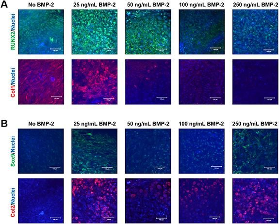
Standard image High-resolution imageImmunofluorescence staining was further used to determine the influence of BMP-2 on chondrogenic differentiation. Osteogenic differentiation markers RUNX2 (green) and Collagen type I (Col1; red) were used to visualize osteogenic differentiation (figure 7(A)), and chondrogenic differentiation was visualized using Sox9 (green) and Collagen type II (Col2; red) (figure 7(B)). The cultures without any BMP-2 still showed relatively abundant expression of RUNX2 and Col1, indicating some levels of osteogenic differentiation. The addition of BMP-2 and its effects on RUNX2 expression did not present a distinct trend, but the inclusion of 100 ng ml−1 and 250 ng ml−1 of BMP-2 displayed a dramatic decrease in RUNX2 expression. Meanwhile, the Col1 expression decreased in a dose-dependent manner with lower doses of BMP-2 (25 and 50 ng ml−1), while no expression was observed for higher doses (100 ng ml−1 and 250 ng ml−1) of BMP-2. On the other hand, the cells cultured without BMP-2 did not express much Sox9 or Col2, and were undergoing minimal chondrogenic differentiation. The groups with 50 ng ml−1 and 100 ng ml−1 of BMP-2 also did not show high levels of Sox9 expression. However, the cultures treated with 25 ng ml−1 and 250 ng ml−1 of BMP-2 expressed higher levels of Sox9. As for Col2 expression, all groups treated with BMP-2 expressed higher levels of Col2, with 25 ng ml−1 of BMP-2 group showing the highest level of Col2 expression.
Figure 7. Synergistic effects of BMP-2 and TGF-β1 on MSC chondrogenesis. Immunofluorescence imaging via confocal microscopy of (A) osteogenic, RUNX2 (green, top) and Collagen Type I (Col1; red, bottom), as well as (B) chondrogenic, Sox9 (green, top) and Collagen Type II (Col2; red, bottom), proteins in the 21 days cultured cell pellets showing osteogenic protein expression is down-regulated in the presence of increasing amounts of BMP-2 while chondrogenic protein expression is up-regulated in the presence of BMP-2.
Download figure:
Standard image High-resolution image
4. Discussion
We used a combined thermal sintering and porogen leaching method for the development of a template scaffold with structural strength required to support OC tissue regeneration [15, 35, 36]. A porosity gradient in the scaffold was achieved by increasing the porogen content along the scaffold length. The porosity gradient confirmed through micro-CT analysis (figure 1) showed the template pore volume gradually increased from the bottom to the top. This increase in pore volume was further used to introduce a gel phase into the template. Hyaluronic acid gel was chosen as it is an integral part of cartilage extracellular matrix and has been shown to support MSC chondrogenesis [17, 55–58]. The gel phase infusion into the gradient template gave rise to opposing/inverse gradients for the PLGA and gel phases. This arrangement resulted in an inverse matrix system with gradual transition from the cartilaginous region down to the osseous region. This transition between the chondrogenic and osteogenic regions of the scaffold would provide material and structural cues for the development of a bone-cartilage interface while maintaining structural integrity of the scaffold and regenerated tissue [59–62].
To enhance the capabilities of the inverse gradient scaffold system to support bone-cartilage interface formation, osteogenic and chondrogenic growth factors were incorporated. For growth factor loading, template material PLGA was formed into a composite by combining with HAp, which is the mineral component found in natural bone and is known for being osteoinductive and bioactive [63]. Moreover, HAp addition to biodegradable polyesters has been shown to improve protein adsorption capacity due to the electrostatic interactions between amino groups of the proteins and the negatively charged sites of the HAp particles [63–65]. SEM imaging and EDS analysis demonstrate HAp presence on the scaffold surface (figure 3(A)). Although the distribution of HAp nanoparticles along the surface of the PLGA microspheres are sparse, the exposed HAp presents additional electrostatic binding sites for the loaded BMP-2 to interact with. Oxygen plasma treatment was also utilized to further improve BMP-2 adsorption to the scaffold and subsequent release. The plasma-treated template scaffold was found to show decreased contact angle, therefore increased wettability. The increase in hydrophilicity via plasma treatment can be attributed to the addition of OH− groups on the surface of the polymer [66, 67]. The increase in hydrophilicity and introduction of additional functional groups on the surface of PLGA via plasma treatment has been demonstrated to increase growth factor loading [68–70]. Therefore, in combination with HAp nanoparticles, the growth factor binding affinity of the PLGA:HAp scaffolds has been enhanced to allow for localization of the loaded osteogenic growth factor.
In the inverse matrix, the osteogenic growth factor BMP-2 was adsorbed to the surface of the PLGA, while the chondrogenic factor TGF-β1 was loaded into the hyaluronic acid gel phase. The resulting scaffold displayed localization of the model chondrogenic factor to the upper portions of the scaffold, while the model osteogenic factor was detected with the PLGA template structure. The scaffold developed in this study features dual-factor loading with spatial control of the loaded factors. In particular, the chondrogenic factor localized in the gel phase is aimed to promote chondrogenesis in the distal part of the matrix, while the osteogenic factor is associated with PLGA to promote osteogenesis in the template structure. However, this method of growth factor loading may be altered to provide spatial isolation of the two growth factors by partially submerging the PLGA scaffold in BMP-2 solution, as opposed to loading BMP-2 throughout the scaffold. In addition, limiting HAp to the lower portions of the PLGA template may also provide localized growth factor affinity and aid in spatial control of growth factor loading.
The in vitro testing of the developed OC scaffold system was designed to mimic the infiltration of native MSCs into the lower half of the scaffold from host bone marrow. After separately culturing the top (distal) and bottom (proximal) portions of the scaffold, the upper portions of the scaffold showed greater GAG deposition than the lower half of the scaffold. This increased deposition of GAG indicates greater chondrogenesis, which can mainly be attributed to the localization of TGF-β1 in the upper portions of the graft. However, evidence of osteogenesis was seen in both the top and bottom portions of the scaffold, and similar levels of mineralization indicated osteogenesis of cells in both regions of the graft. This could be attributed to the presence of the β-glycerophosphate in the co-differentiation media, HAp in the scaffold, and/or BMP-2 in the distal layer. β-glycerophosphate, a common additive to induce osteogenesis in vitro, may have induced mineralization in the upper portions of the matrix as it serves as the source of phosphates during precipitation of HAp [71]. In addition, HAp, along with being a well-known osteogenic factor, is known to promote additional passive precipitation of calcium apatite when introduced to an aqueous environment with calcium and phosphate ions, such as cell culture media [72, 73]. Therefore, these previous results do not clearly show whether the mineralization seen was due to passive precipitation of calcium apatite or active cellular mineralization brought on by osteogenesis due to the presence of BMP-2 throughout the scaffold.
To isolate the effects of BMP-2 on the apparent osteogenesis of the cells seen in the cartilaginous section of the scaffold, hMSC cell pellets were cultured in the presence of TGF-β1 and BMP-2, without the addition of β-glycerophosphate and HAp. The effects of exogenous BMP-2 on hMSC chondrogenic differentiation, assessed through GAG quantification and immunofluorescence staining, showed that BMP-2 enhances chondrogenesis beyond culturing with regular chondrogenic media alone. Increasing the amount of BMP-2 added to the culture increased the amount of GAG produced by the cells in a dose-dependent manner. The expression of chondrogenic markers were also increased with the addition of BMP-2, although not in a directly proportional manner as seen with GAG expression. Osteogenic response of the cells cultured with BMP-2 and TGF-β1 was also minimal and showed no significant difference between the cells cultured with or without BMP-2.
The synergistic effects of TGF-β1 and BMPs on MSC chondrogenesis have been well established and further support the effects of TGF-β1 and BMP-2 seen in this study [39, 40, 74–76]. Studies using isolated MSCs [40] and cartilage explants [75] have shown that when TGF-β1 and BMP-2 are used in conjunction, chondrogenic marker expression, such as Col2, Sox9, GAGs, and aggrecan, were increased. The inhibition of downstream differentiation of the cells within the explant into hypertrophic cartilage has also been reported [75]. Similar results were also reported when chondrocytes were cultured on chitosan-based hydrogels with TGF-β1 and BMP-7 [76]. Studies also confirmed the importance of Smad signaling in the synergistic effects of BMP and TGF-β signaling, noting that the dual growth factor treatment results in an increased expression of Smad8, responsible for BMP signal transduction, while downregulating the expression of Smad3, which enhances osteogenic response of MSCs [76, 77]. Therefore, when considering the results from this study and the previously published synergistic effects of the two growth factors used on chondrogenesis, the mineralization seen in the upper portion of the scaffold may be due to the presence of HAp and β-glycerophosphate, rather than the co-localization of BMP-2 and TGF-β1.
5. Conclusions
Our study developed a unique OC matrix system with biodegradable PLGA template with gradient pore volume and hyaluronic acid gel. The integration of these two phases established an inverse matrix with continuous material gradients along the scaffold length. The adsorption of an osteogenic factor into the template and incorporation of a chondrogenic factor into the gel phase resulted in the formation of an OC graft with spatial growth factor loading and distribution. The dual growth factor profile was shown to be beneficial in chondrogenesis in the upper, cartilaginous region of the scaffold, while also supporting osteogenesis in the lower, osseous phase of the scaffold. Consequently, the developed inverse gradient matrix system with spatial growth factor arrangement is advantageous in promoting bone-cartilage interface formation—a critical need in developing effective OC TE scaffolds.
Acknowledgments
The authors acknowledge support from the National Institute of Biomedical Imaging and Bioengineering of the National Institutes of Health (#R01EB030060 & #R01EB020640). Dr. Nukavarapu also acknowledges funding from NSF EFMA (#1640008 & 1908454), and the University of Connecticut for SPARK and REP awards. Thanks to Dr Adams for helpful discussion on Micro-CT data and analysis, and Drs Bonin and Hargis for help editing the manuscript.