
Abstract
Understanding the distribution of critical elements (e.g. silicon and calcium) within silica-based bone scaffolds synthesized by different methods is central to the optimization of these materials. Time-of-flight secondary ion mass spectrometry (ToF-SIMS) has been used to determine this information due to its very high surface sensitivity and its ability to map all the elements and compounds in the periodic table with high spatial resolution. The SIMS image data can also be combined with depth profiles to construct three-dimensional chemical maps. However, the scaffolds have interconnected pore networks, which are very challenging structures for the SIMS technique. To overcome this problem two experimental methodologies have been developed. The first method involved the use of the focused ion beam technique to obtain clear images of the regions of interest and subsequently mark them by introducing fiducial marks; the samples were then analysed using the ToF-SIMS technique to yield the chemical analyses of the regions of interest. The second method involved impregnating the pores using a suitable reagent so that a flat surface could be achieved, and this was followed by secondary ion mapping and 3D chemical imaging with ToF-SIMS. The samples used in this work were sol–gel 70S30C foam and electrospun fibres and calcium-containing silica/gelatin hybrid scaffolds. The results demonstrate the feasibility of both these experimental methodologies and indicate that these methods can provide an opportunity to compare various artificial bone scaffolds, which will be of help in improving scaffold synthesis and processing routes. The techniques are also transferable to many other types of porous material.
Export citation and abstract BibTeX RIS
1. Introduction
For bone regeneration, an ideal synthetic bone graft must fulfil many critical criteria simultaneously such as bioactivity, osteoinduction, osteoconduction, satisfactory mechanical properties and have a porous interconnected pore network that encourages bone and blood vessel ingrowth [1–5]. Bioactive glass granules are used because they can bond to bone, degrade in the body and stimulate bone growth [5–8]. Bioactive glasses can be melt- or sol–gel derived. The sol–gel process has the advantage that it is easier to produce porous scaffolds that retain the amorphous structure of the glass from sol–gel processes than it is from commercially available melt-derived glasses. The latter tend to crystallize on sintering.
One such sol–gel composition is 70S30C (70 mol.% SiO2 and 30 mol.% CaO). 70S30C has very high bioactivity and bonds to bone while being remodelled leaving regenerated bone [5, 9–12]. Sol–gel scaffolds can be produced in various forms of porous scaffold, e.g. foams by the foaming process [3, 7] and electrospun fibres [13]. These scaffolds are promising materials for regenerating bone in non-load bearing defect sites; however they are not suitable for bone defect sites that are under cyclic loading due to their brittle nature. Therefore inorganic/organic hybrid materials have been developed to provide toughness [8, 14, 15]. In a hybrid the inorganic and organic components form an interpenetrating network at the molecular level. Hence the different components are not distinguishable above the submicron scale. In addition, the hybrids also have the potential to have excellent mechanical properties such as high toughness and can degrade congruently as one material [8, 16–20].
For the optimization of such silica-based bone grafts, an important step is calcium incorporation since calcium is vital for the formation of the hydroxycarbonate apatite (HCA) layer, which has a great influence on stimulating new bone formation [21, 22]. Therefore, key to the development and improvement of such biomaterials will be an understanding of the distribution of the critical elements (silicon, which is the backbone of the inorganic network, and calcium) in the 3D network. Yue et al applied synchrotron x-ray microtomography (µCT) to successfully observe an enhanced calcium distribution near the surface of the 70S30C bioactive glass foam due to the synthesis process [23]. Jallot et al investigated the surface physicochemical reactions of a bioactive glass scaffold (75 wt% SiO2 and 25 wt% CaO) ex vivo by using particle-induced x-ray emission (PIXE) associated with Rutherford backscattering spectroscopy (RBS) and major, minor and trace elemental maps and quantification were obtained in such porous material [24]. However, information on compound species cannot be obtained by these techniques, which is a limitation for biological and organic materials.
Time-of-flight secondary ion mass spectrometry (ToF-SIMS), a powerful analytical tool in material science, has been acquiring a pivotal role in the biological and biomaterial fields due to its high surface sensitivity (from the top 2–3 atomic layers) and its ability to map all the elements and even compounds with high spatial resolution [25–29]. Also, by introducing a second ion beam for etching ToF-SIMS can be used to depth profile materials and hence to construct three-dimensional ion images (chemical maps). The time-of-flight analyser has very high transmission (>50%) and thus high sensitivity (up to the range of ppb). In addition, excellent mass resolution, i.e. exceeding 10 000 (m/Δm), can be attained [30].
However, SIMS is a surface sensitive technique and thus the accuracy of the SIMS results is topography dependent [25] and the secondary ion yield and the sputter yield both depend upon the angle of incidence of the primary ion beam with respect to the sample surface. Roughness in the sample surface can deteriorate and even, sometimes, destroy the information in the results. Thus, many of the artificial porous bone grafts are challenging for the SIMS technique. For instance, porous scaffolds fabricated by the foaming process have interconnected pore networks, which lead to extreme difficulty in SIMS analysis unless the sample is modified. Also, locating the very small struts of interest becomes an added complication. As a consequence, the sample preparation procedure is a critical issue and should be carefully considered with the aim of producing a flat surface for the SIMS analysis.
In this paper, we will propose and demonstrate two experimental methodologies, soak & solid and mark & map, to overcome the topography issue presented by porous scaffolds, so that SIMS analysis on highly porous scaffolds becomes feasible. Here, three different types of sol–gel bioactive artificial bone scaffolds with various pore sizes and structures were investigated: a 70S30C glass foam and a novel calcium-containing silica/gelatin hybrid scaffold, both synthesized by the sol–gel foaming process, and 70S30C glass fibres fabricated by the electro-spinning technique. Each of the scaffolds mentioned was extremely challenging for the SIMS technique (figure 1) and therefore two corresponding strategies were evaluated.

Figure 1. SEM images of (a) a 70S30C bioactive glass scaffold produced by the sol–gel foaming process, (b) electrospun 70S30C bioactive glass sol–gel fibres and (c) a calcium-containing silica/gelatin sol–gel hybrid scaffold (50 wt% gelatin and the molar ratio of silicon to calcium to phosphorus was 70:10:5). Each of these materials presents SIMS with some challenges.
Download figure:
Standard image High-resolution imageSoak & solid involves impregnating a suitable reagent into the pores to flatten the sample surface. The challenge then becomes the choice of appropriate reagent. It must at least satisfy these requirements: (1) it should be inert to avoid reacting with the sample or destroying the structure; (2) it should flow easily and then solidify within the sample; (3) it cannot contain any element of interest in order not to interfere with the SIMS analysis; (4) the sputter rate it experiences should be very similar to that of the sample (i.e. the matrix). Due to the restrictions above the choice of the reagent varies with different materials. Here, epoxy resin was selected and applied to all three types of 70S30C glass scaffolds; however, since resin is incompatible with organic materials and therefore inorganic/organic hybrids due to its organic nature, the following method was proposed for such materials.
Mark & Map involves the combination of the focused ion beam (FIB) to locate the strut of interest and the ToF-SIMS for secondary ion mapping. This strategy is based on the fact that the video camera resolution of the ToF-SIMS is too poor to locate a very small strut while clear SE/SI images and fiducial marks can be obtained by FIB-SEM/SIMS to indicate the struts of interest. Therefore, combining both techniques provides an opportunity to analyse some challenging structures with SIMS. In addition, the SIMS data obtained with this approach will be more convincing as no additive is used for sample modification/embedment. The calcium containing silica/gelatin hybrid foam was used for testing this method.
2. Materials and methods
2.1. 70S30C bioactive glass foam synthesis
The sol–gel derived bioactive glass foams 70S30C with the nominal composition of 70 mol.% SiO2, 30 mol.% CaO were prepared as described previously [3]. The sol–gel precursor solution for foaming was prepared by acid hydrolysis of tetraethyl orthosilicate (TEOS) using a molar ratio of water to TEOS (R ratio) of 12:1. Calcium was added using calcium nitrate tetrahydrate (all reagents from Sigma). Fifty millilitres aliquots of sol were foamed by vigorous agitation with the addition of 0.5 ml of the surfactant Teepol (Thames Mead Ltd, London) and 2.0 ml 5 vol% HF (a gelation catalyst). The foamed solution was cast into cylindrical polymethyl propylene moulds as soon as the gelling point approached and the moulds were sealed. The cylindrical discs of foam (∼15 mm height and 25 mm diameter) produced were then aged, dried and thermally stabilized at 700 °C and furnace cooled.
2.2. 70S30C bioactive glass fibre synthesis
Sol–gel precursor solutions for the production of 70S30C fibres were prepared by mixing TEOS, ethanol, deionized water and 1 N hydrochloric acid with the molar ratio of 1:2:2:0.01. Calcium was added to the composition as calcium nitrate tetrahydrate. The 70S30C precursor solutions were allowed to react for 24 h at room temperature followed by heating at 70 °C in an oven while continuously mixing. After evaporation of a given amount of solvent the sol–gel precursor solutions were loaded into a glass syringe with a metallic needle (22 gauge) attached to it. This was then electrospun on the Nanofiber Electrospinning Unit (NEU, Kato Tech Co., Japan) and a high tension field of 10 kV was applied to the metal needle. The fibres were collected on Teflon-coated aluminium foil placed on a rotating drum that was positioned at a distance of 100 mm from the capillary. The electrospun fibres were then dried at 60 °C and stabilized at 600 °C.
2.3. Silica/gelatin hybrid scaffold synthesis
The silica/gelatin hybrid scaffold (50 wt% gelatin with a molar ratio of silicon to calcium to phosphorus of 70:10:5) was synthesized using a variant of the sol–gel process modified from previous work [16]. A sol was prepared using TEOS and gelatin with 3-glycidoxyproyltrimethoxysilane (GPTMS) acting as a covalent coupling agent. Functionalizing gelatin with GPTMS allows bonds to form between the silica and the gelatin (the molar ratio of GPTMS : gelatin was 1000) [16]. Mono calcium phosphate was used as a soluble calcium source. A surfactant was introduced in the presence of a gelation catalyst (hydrofluoric acid) and vigorous agitation was used to produce a foam. At the onset of the gelling point the foam was poured into moulds which were then tightly sealed. The samples were then heat treated for 96 h at 40 °C before being freeze dried to obtain the final scaffolds.
2.4. SEM topography characterization
The morphology of the 70S30C foam and silica/gelatin hybrid scaffold coated with gold was imaged by using a scanning electron microscope (JEOL JSM-5610 LV, Japan) with an operating voltage of 15 kV. A field emission scanning electron microscope (Leo 1525 Gemini, Germany) with a gun voltage of 5 kV was applied to study the microstructure of the electrospun 70S30C fibres coated with chromium.
2.5. Soak & Solid
Electrospun 70S30C fibres and three 70S30C foams (S1, S2 and S3) were investigated by this method. Sample preparation before ToF-SIMS analysis was done by filling the pores of the samples with epoxy resin (EpoThin®, BUEHLER) by pressure impregnation. The resin mixture was prepared with a ratio of approximately ten parts of epoxy resin to four parts of hardener by weight. After solidification the bulk was ground and polished down to 4000 grit so that a flat sample surface was obtained. Drying was required in a 40 °C oven to remove any moisture.
A ToF-SIMS instrument (TOF.SIMS 5, ION-TOF GmbH) was then used to analyse these samples. A Cs+ sputter beam with a voltage of 1 keV was used to eliminate the sample surface contaminant prior to collecting any chemical information (for S1 a 10 keV  cluster gun was used). Charge compensation using a low-energy 20 eV electron flood gun was carried out in all analyses. All the samples were imaged by using the 25 keV
  liquid metal ion source (LMIS) of about 0.1 pA with a cycle time of 100 µs in the burst alignment mode, except for S1 where the Bi+ beam with a current of 0.33 pA was used. In the burst alignment mode the primary ion beam is not bunched and the pulse time of primary ion bombardment is long (>80 ns); therefore, an excellent lateral resolution of ∼250 nm can be obtained [28, 31, 32]. For the electrospun 70S30C fibres ToF-SIMS imaging was obtained on a 150 µm × 150 µm area at an accumulated ion dose intensity of 3.54 × 10¹³ ions cm−2. In terms of the 70S30C foam, each of three struts (S1, S2 and S3) was rastered over an area of 500 × 500 µm2 for secondary ion mapping. The depth profiles were generated by using a 1 keV Cs+ gun of approximately 95 nA to sputter the sample surface and form a 800 µm × 800 µm crater. The sample was sputtered each time after generating a secondary ion map (a scan) and a total of 500 scans was obtained, except for S1 (1500 scans), to observe more information inside the material. The sputter time was 1 s per scan, followed by 0.1 s pause time for charge compensation.
2.6. Mark & Map
For organic porous materials, resin embedment is not applicable to SIMS analysis due to the masking and contamination of the organic phase by the same organic compounds in epoxy; therefore, mark & map was applied here to overcome this issue. A novel calcium containing silica/gelatin hybrid scaffold was investigated. To enable the SIMS technique to analyse this porous hybrid material, a FIB-SIMS (FIB200-SIMS, FEI Ltd) equipped with a Ga+ LMIS was used to obtain clear secondary-ion images to determine the small strut of interest, followed by fabricating a FIB-milling fiducial mark (i.e. a gallium arrow) to indicate the location (figure 2(a)). The sample was then transferred to the TOF.SIMS 5 instrument for secondary-ion mapping. The gallium arrow could be observed under the video camera of the ToF-SIMS (figure 2(b)) such that the position of the region of interest could be approximately located and further confirmed by the secondary-ion image of ToF-SIMS (figure 2(c)). Once the analysed strut was located, the distributions of the elements and compounds of interest were determined by ToF-SIMS imaging. Secondary-ion mapping with a raster size of 25 × 25 µm2 was acquired in the burst alignment mode by using the Bi+ primary-ion gun with a target current of 0.25 pA at 25 keV energy. The total ion dose was 1.02 × 10¹⁰ ions. A low-energy 20 eV pulsed electron flood gun was used for charge compensation.

Figure 2. Combination of FIB and ToF-SIMS to locate the strut of a calcium-containing silica/gelatin hybrid scaffold: (a) FIB-SIMS secondary-ion image of the FIB fiducial arrow (red rectangle) and the strut of interest (red oval), (b) location of the FIB fiducial arrow (red rectangle) under the video camera of ToF-SIMS and (c) ToF-SIMS secondary-ion image of the strut of interest.
Download figure:
Standard image High-resolution image3. Results and discussion
3.1. 70S30C bioactive glass foam
Figure 1(a) shows the highly porous 70S30C foamed scaffold fabricated through the sol–gel foaming process. Owing to the foaming technique the pores are spherical with numerous circular interconnections between neighbouring pores. The porous morphology of the 70S30C foam is extremely challenging for SIMS analysis. Hence, the soak & solid sample preparation method was employed. The feasibility of the soak & solid technique was verified by comparing the distribution of the total ions (figure 3(a)) and silicon or calcium (figures 3(c) or (d)). In the total ion image, ion signals were observed over the whole sample surface, whereas both the silicon and calcium ion images exhibited a clear strut-shaped distribution. This is due to the fact that the two main components of the 70S30C scaffold, silicon and calcium, did not exist in the epoxy resin with which the pores were impregnated. This thus proves that this technique is applicable to such highly porous materials for SIMS analysis. This technique could be applied to other inorganic materials with open porosity and is therefore transferable to a number of other systems.
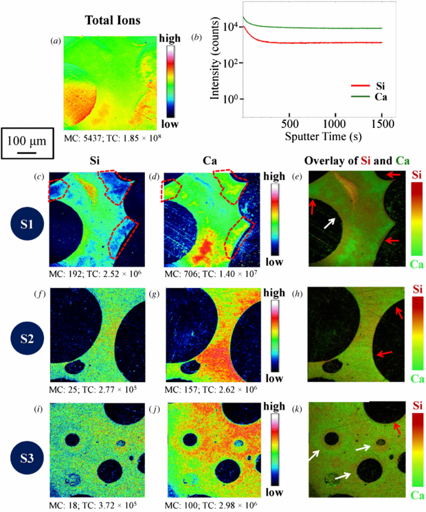
Figure 3. ToF-SIMS analysis of 70S30C bioactive glass scaffolds fabricated by the sol–gel foaming process. The data were obtained from three samples with epoxy resin embedding: (a)–(e) S1, (f)–(h) S2 and (i)–(k) S3. Secondary ion maps revealed the distribution as follows (MC: maximum ion counts; TC: otal ion counts): (a) total secondary ion map of sample 1 (S1); (b) depth profile of sample 1 (S1); (c) (d) (e) elemental maps of sample 1 (S1) for Si, Ca and (Si+Ca); (f) (g) (h) elemental maps of sample 2 (S2) for Si, Ca and (Si+Ca); (i) (j) (k) elemental maps of sample 3 (S3) for Si, Ca and (Si+Ca). The depth profiles of silicon and calcium in S1 (b) are presented to show the intensity of these major ions with sputter time. Field of view 500 × 500 µm2. The white arrows indicate the regions where there is more silicon than calcium while the red arrows show the inverse case. The scale bar is 100 µm for all images.
Download figure:
Standard image High-resolution imageTo evaluate the 70S30C foam synthesis routes, ToF-SIMS secondary ion mapping and depth profiling were performed. Figure 3(b) shows the distribution of silicon and calcium with sputter time. Both elements experienced a high initial intensity which then gradually decreased and levelled off. The initial high intensity could be due to the well-known SIMS pre-equilibrium effects where in the early stages of a depth profile the chemical composition in the near-surface region changes as atoms of the primary ion beam are implanted and the near surface is 'loaded' with atoms of the primary beam. During the pre-equilibrium period the secondary ion yields and sputter yields continuously changed as the near-surface chemistry changed and it was very difficult to quantify the composition of the material. At steady state the rate of implantation of primary species is equal to the rate at which they are sputtered, and sputter rate and secondary ion yield are fixed (in a given matrix). The silicon and calcium signals were parallel in the equilibrium part of the profile indicating that there was no change in composition with depth. It should be noted however that the SIMS depth profile data points are gathered from a large area (500 × 500 µm2) in the crater base and there may be lateral variations in composition.
On examining the Si and Ca ToF-SIMS 2D images (figures 3(c)–(k)), several interesting observations can be made at the interface between the pores and the struts of the foamed scaffolds. Three samples (S1, S2 and S3) were investigated. In the case of sample 1 (S1) silicon-depleted and calcium-rich regions in the same areas highlighted by the red dashed boxes can be found along some of the pore contours in figures 3(c) and (d), respectively. Such regions are indicated by the red arrows indicated in the overlay image of silicon and calcium (figure 3(e)). However silicon-dominant regions can also form at the interface between the pores and the struts, and one such area is indicated by a white arrow, so clearly the situation is quite complicated.
Moving onto sample 2 (S2) and sample 3 (S3), the distribution of silicon was relatively homogeneous (figures 3(f) and (i)) whilst the calcium distribution showed a distinctly higher intensity in some regions compared to others (figures 3(g) and (j)). As with sample S1, the formation of calcium-rich and silicon-depleted regions was observed along some of the pore contours in both samples, and these regions are indicated by the red arrows (figures 3(h) and (k)). For sample S3 the white arrows indicate that silicon tended to be enriched around the small closed pores (figure 3(k)).
Lin et al observed that during the aging process of sol–gel monolith synthesis the calcium and nitrate ions leached out of the silica gel into the pore liquor and on drying re-deposited onto the surface regions of the silica matrix [33]. Later, Yu et al showed that traditional calcium salts such as calcium nitrate and calcium chloride went through this leaching out and re-deposition process during the synthesis of monolithic sol–gel bioactive glasses [34]. Yue et al then qualitatively showed using µCT that there was a preferential deposition of calcium near the surface of the 70S30C foamed scaffolds [35]. It was generally believed that the theory of leaching out/re-deposition was also applicable to foamed scaffolds. However, the SIMS evidence in this study clearly indicates that there is not a clear trend for the re-deposition of calcium near or at the surface regions of the scaffold walls. The ToF-SIMS data have shown that the simple model of calcium being rich near the interface between pores and the struts of the foamed scaffold is not absolutely applicable and therefore during the aging process pore liquor does not necessarily form around the foamed scaffold gels in the way that was described by Lin et al for the 70S30C monoliths. This suggests that a more detailed study investigating the way the pore liquor develops in and around the foamed 70S30C gels should be undertaken to further explain the pattern of calcium deposition seen in these images. In addition, the heterogeneous distribution of the two main components (silicon and calcium) suggests that the silica network and the calcium nitrate source cannot be evenly dispersed into the scaffolds during the synthesis process.
3.2. Electrospun 70S30C bioactive glass fibre
During electrospinning the application of a high tension electric field causes the solution to be highly charged. When the repulsion of the charges within this solution is greater than the surface tension a Taylor cone is formed (figure 4). From this a stable jet is ejected which travels towards the grounded collector. The stable jet undergoes bending and whipping instabilities which are responsible for thinning the initial jet such that nanofibres can be obtained. In the electrospinning of 70S30C sol–gel fibres sub-micron diameter sized long fibres were produced (figure 1(b)). It was hypothesized that the application of a high voltage to the 70S30C sol–gel solution could lead to separation of charges such as Ca2+ and SiO4− which could result in phase separation along the fibres. The SIMS technique is ideal to prove or disprove this hypothesis; however the extremely porous topography as seen on the SEM image in figure 1(b) meant that the soak & solid sample treatment was required.

Figure 4. Schematic illustration of the synthesis of electrospun 70S30C sol–gel glass fibres. The zoom-in SEM image suggests that positive charges may be pushed to distribute in the fibre end due to the same-charge repulsion from the jet device.
Download figure:
Standard image High-resolution imageFigure 4 briefly illustrates the possibility of calcium-dominant formation on fibre ends during the synthesis process of electrospun 70S30C fibres. The redistribution and accumulation of Ca2+ at oriented ends may occur due to the same-charge repulsion from the positively-charged Taylor cone. ToF-SIMS secondary ion maps for silicon and calcium are shown in figures 5(a) and (b) respectively, and the overlay image of both elements is presented in figure 5(c). Red circles are placed around a calcium-rich aggregation with high intensity where there was no silicon signal. The calcium circle was approximately 4 µm in diameter, which is consistent with the dimensions of the fibres obtained by the SEM image (figure 1(a)). To further verify the existence of the fibre end a SEM image was taken on the same area of the ToF-SIMS images. Figure 5(d) clearly indicated that a round-shaped structure beside the fibres embedded in the epoxy resin can be observed; therefore, the fibre end repelled by the jet device did capture calcium with high concentration. Figures 5(a) and (b) showed the inhomogeneity of the silicon and calcium distribution along the fibres. This suggests that during the electrospinning process in the short time of going from a homogeneous solution to a solidified fibre the calcium has time to diffuse and cause microscale phase separation that could be observed with SIMS. Although more weight is required to support the proposed hypothesis, SIMS was beneficial in this case in providing a clear understanding of the distribution of Si and Ca along the fibre.

Figure 5. ToF-SIMS secondary ion maps showing the distribution of (a) silicon, (b) calcium and (c) an overlay image of silicon (red) and calcium (green) in the electrospun 70S30C sol–gel glass fibres with epoxy resin embedment. (d) SEM image of the same fibres indicating the existence of the fibre end. (MC: maximum ion counts; TC: total ion counts.)
Download figure:
Standard image High-resolution image3.3. Calcium containing silica/gelatin hybrid scaffold
The mark & map technique provides an opportunity to analyse porous organic materials by SIMS. In addition, SIMS analysis without any sample modification enables more reliable information to be obtained. Here, a novel calcium-containing silica/gelatin hybrid scaffold synthesized by the sol–gel foaming process was investigated using this technique. The molecular structure of the silica/gelatin hybrids has been reported in previous work [16]. However, in this work calcium incorporation into such hybrid materials was attempted for the first time. A soluble calcium phosphate was used and ToF-SIMS used to inspect the distribution of some critical elements, thereby evaluating the feasibility of such a calcium source.
Figure 6 illustrates the molecular structure of this new hybrid system with calcium incorporation estimated from the SIMS data. The heterogeneous distribution of all elements and compounds indicated that the hybrid sol cannot be thoroughly dispersed in the scaffold during the processing routes. An enhanced secondary ion intensity can be observed at the bottom right hand corner of all images, which may be due to a SIMS charging effect in which small variations in surface potential lead to non-uniform secondary ion emission across the crater base. However, the images are still very useful and some important trends can be seen in the silicon and calcium maps. The distribution of the silicon was fairly uniform whilst the calcium tended to aggregate and formed a particle-like structure. Mahony et al showed that gelatin can be covalently linked to the silica network through the coupling agent GPTMS [16]. The SIMS data (figure 6) support their data. The similar distribution of SiOH (the silica network) and the C–SiO2 bonding (the link between GPTMS and the silica network) and the silicon distribution indicate that the silica and gelatin are interpenetrating networks with covalent bonds between the components: a true hybrid. Therefore, the different trends of silicon and calcium distribution suggests that the calcium phosphate source cannot be successfully incorporated into the hybrid system, rather it remains heterogeneously distributed after the hybrid scaffold fabrication.

Figure 6. Estimated schematic of a calcium-containing silica/gelatin hybrid scaffold used in this work and ToF-SIMS secondary ion maps for the corresponding critical elements and compounds. Scale bar is 10 µm for all images. (MC: maximum ion counts; TC: total ion counts.)
Download figure:
Standard image High-resolution image
However, figure 6 shows that the distribution of the covalent bonding (C–N bonds) between the components may not be homogeneous. GPTMS is a small molecule with an epoxide ring on one end and three methoxysilane groups on the other. The gelatin was functionalized with GPTMS prior to adding it to the sol. The COOH groups on the gelatin are hypothesized to open the epoxide ring through nucleophilic attack so that the gelatin is functionalized with trimethoxysilane groups [36]. When the functionalized gelatin is added to a sol (hydrolysed TEOS), the methoxysilane groups should hydrolyse, leaving Si-OH groups that can condense with Si–OH groups in the silica network, covalently coupling the gelatin to the silica [16].
Here, C–N bonds were detected with the SIMS. The C–N bonds can only be sputtered from the amine group of the gelatin. The distribution of the C–N bonding inferred that part of the gelatin and thus the silica network was functionalized with GPTMS, while a proportion was not. As a consequence, the calcium phosphate may also be incorporated into two groups: the covalently coupled gelatin and the 'free' gelatin. The gelatin may still interact with the silica through hydrogen bonding. The phosphorus ion map was consistent with this hypothesis, exhibiting a distribution between that of silicon and calcium and thus more homogeneity. Two calcium containing species (C–N–Ca and Ca–O) represented two different calcium incorporation routes respectively. Calcium can be chelated into the hybrid system through the carboxylic group [22]. The CaO ion image suggested such an occurrence and showed that the distribution was similar to that of free calcium. It can consequently be inferred that the reaction happened between the gelatin that was not covalently coupled and calcium phosphate. The C–N–Ca bonding implied another possibility, namely that calcium may also react with amine groups in the gelatin. The C–N–Ca secondary ion map showed that the C–N–Ca distribution was between that of Ca and Si but more resembled the Si distribution. This may suggest that calcium tends to be incorporated into the hybrid system through the amine group. This can be easily explained since the carboxylic group from the gelatin in the hybrid was used to covalently link the GPTMS and therefore many were occupied. However, incorporating calcium into this silica/gelatin hybrid scaffold as a soluble calcium phosphate is not suitable for producing a homogeneous composition. Therefore, another method of introducing calcium has to be devised.
4. Conclusion
In this work development of sample preparation methodologies prior to the SIMS analysis of various highly porous bioactive bone scaffolds was investigated. 'Soak & solid', i.e. impregnating the material with a suitable reagent to fill the pores, proved to be a promising way to obtain a flat sample surface for the SIMS technique. Resin embedding facilitated ToF-SIMS comparison of porous 70S30C bioactive glass scaffolds produced by foaming process and electrospinning. For 70S30C foam, in some cases more calcium was distributed along the contour of the pores as the calcium could dissolve in the synthesis by-products and was therefore driven to open pores for evaporation. After drying, calcium re-deposited on the pores. For the electrospun 70S30C fibres, calcium accumulated on the fibre ends, which could be attributed to same-charge repulsion from the fibre jet device.
For organic or inorganic/organic hybrid scaffolds, the 'mark & map' technique provided a strategy to overcome the masking of the same organic compounds caused by the resin. A gallium fiducial mark was fabricated to locate the strut of interest by the FIB and secondary ion maps were thus obtained by the ToF-SIMS. Combining both FIB and ToF-SIMS instruments provides an opportunity to analyse a very small region of interest in an extremely rough bulk sample using the SIMS technique. In addition, more convincing data can be obtained without any modification/embedment. The results showed that calcium and silicon had distinct and heterogeneous distributions. This suggests that calcium phosphate is not an optimal precursor for the sol–gel hybrid synthesis.
Both methodologies demonstrated the ability to compare various artificial bone scaffolds with high porosity, which will facilitate the optimization of their fabrication routes and thus the properties of the scaffolds. These strategies can also be applied to many other types of porous material, and so they will be of help more generally in the SIMS analysis of highly porous materials.
Acknowledgments
The authors would like to thank EPSRC for funding the project (EP/H006060/1 and EP/I020861/1). The authors are also indebted to Dr Sarah Fearn of Imperial College London for her great help with the TOF.SIMS 5 experiments.