

Abstract
Flapping-wing micro air vehicles (FWMAVs) are a class of unmanned aircraft that imitate flight characteristics of natural organisms such as birds, bats, and insects, in order to achieve maximum flight efficiency and manoeuvrability. Designing proper mechanisms for flapping transmission is an extremely important aspect for FWMAVs. Compliant transmission mechanisms have been considered as an alternative to rigid transmission systems due to their lower the number of parts, thereby reducing the total weight, lower energy loss thanks to little or practically no friction among parts, and at the same time, being able to store and release mechanical power during the flapping cycle. In this paper, the state-of-the-art research in this field is dealt upon, highlighting open challenges and research topics. An optimization method for designing compliant transmission mechanisms inspired by the thoraxes of insects is also introduced.
Export citation and abstract BibTeX RIS
1. Introduction
Flapping-wing micro air vehicles (FWMAVs) are a class of unmanned aircraft that imitate flight characteristics of natural organisms like birds, bats, and insects. Research on FWMAVs has been carried out over the past years. The interest in this subject has increased due to its suitability for many potential applications especially in confined spaces, from search and rescue in buildings or inside collapsed structures, sensing of chemical leaks in industry, detection of radiations in nuclear plants as well as surveillance and reconnaissance [1]. The interest of this kind of flying robots is also due to the fact that, as the size of the vehicles get smaller, standard mechanisms like rotating blades do not perform as well flapping systems, because of low Reynold numbers.
FWMAVs mainly contain two kinds of aerial vehicles. One is the bird-size flapping-wing aerial vehicle, which is generically called 'ornithopter'. The other is the insect-size flapping-wing aerial vehicle which, mainly mimics flapping wing motions of insects or very small birds (e.g. hummingbirds) [2]. Additionally, in 2005, the US Defense Advanced Research Projects Agency (DARPA) introduced the aerial vehicles into nano scales, in which the vehicles are no larger than 7.5 cm or heavier than 10 g (carrying a 2 g payload).
The main components of FWMAVs consist of a power source, actuators, control units, flapping transmission mechanisms, wings, and other supporting structures [3]. This paper is focused on the flapping transmission mechanism, which is functionally responsible for the conversion of the rotational or linear movements of the actuators to the desired flapping motions. Currently, most flapping-wing aerial vehicles use rigid-body mechanisms for their transmission systems due to high forces transmitted and easier controllability. Gerdes et al [4] categorized flapping mechanisms used in bird-size FWMAVs into four classifications: (1) front mounted double pushrods; (2) front mounted double cranks; (3) front mounted single pushrod; and (4) side-mounted crank [4]. Primary representative designs of the types (1) and (3) are shown in figure 1 and examples for types (2) and (4) can be found in [4]. Insect-size FWMAVs, like Nano Hummingbird [5], usually do not have tails and only use a couple of wings with large flapping amplitudes and high flapping frequency to control their attitude. In this case, much more complicated flapping driving mechanisms are required. Recently, some interesting attempts of transmission mechanisms, such as the dual series four-bar linkage and string-based designs [5], the six-bar linkage design [6], the rack-pinion mechanism [7], and the Watt straight-line linkage system [8], have been proposed for FWMAVs.
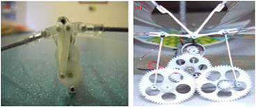
Figure 1. Representative models of primary rigid-body transmission mechanisms. (a) Front mounted double pushrods (Chung Hua University, FWMAV [9]). Reprinted from [9], Copyright (2009), with permission from Elsevier. (b) Front mounted single pushrod (Wright State University, FWMAV [10]). Reproduced with permission from [10] Copyright © 2010 by the American Institute of Aeronautics and Astronautics, Inc.
Download figure:
Standard image High-resolution imageUnlike rigid-body mechanisms, compliant mechanisms generally contain flexural joints, segments or other elastic components, which can transform motion, forces and energies through the deformation of the compliant elements. Compared to rigid-body mechanisms, compliant mechanisms have several benefits, such as reduced wear, no friction and backlash, and compatibility with micro-electro-mechanical system (MEMS) processing techniques [11, 12]. These advantages make compliant mechanisms suitable for designing FWMAVs.
The objective of this paper is to present the current state-of-the-art in the design of compliant transmission mechanisms inspired by biological organisms for FWMAVs. The structure of this paper is as follows. A brief description of flapping-wing micro aerial vehicles and the benefits of using compliant transmission mechanisms are introduced in the first section. Section 2 introduces some biological bases. It also reviews representative designs of compliant transmission mechanisms inspired by the thorax structures of insects. A classification of compliant transmission mechanisms (CTMs) according to the type of actuators is also presented. In section 3, an optimization method for designing compliant flapping mechanisms combined with pseudo-rigid-body (PRB) theory and the principle of virtual work, proposed in former work [13] are briefly introduced. Finally, section 4 presents a summary of open challenges and section 5 presents conclusions of this paper.
2. Compliant transmission mechanisms
2.1. Bio-inspiration
The capability to store and release elastic energy is an important characteristic of most animals' locomotion systems, for flight, in legged locomotion, as well as in undulatory fish swimming.
Here, we focus on mechanisms for storing and releasing elastic energy at high rates for flapping-wing flight. During flapping, as a wing approaches the end of each stroke, the kinetic energy of the wing is stored in the musculoskeletal system, decelerating the wings toward the end of a wing stroke and minimizing the sharp shock of the beating wing. Afterwards, the stored elastic energy is released, helping accelerating the wing. The kinematic energy is stored mainly in two ways: in the flight muscle system [14, 15] and in the elasticity of the thoracic skeleton (including the cuticle and wing hinges) [16].
This paper is centered on the thoracic skeleton system. As Wootton [17] pointed out, the insect thorax is an interesting system of light, thin composite shells and plates, which is interesting for FWMAVs due to the minimal inertial of its moving parts. Springy, resilient structures, which deform elastically and are capable of elastic energy storage, are also beneficial for an oscillating system. Fair insensitivity to scaling effects is another advantage of insects' thoraxes.
Therefore, to design a small, effective and versatile flapping mechanism, engineers have centered their attention to the thorax of the insects. The insects' thorax can be described as as a box with the sides (pleura) and base (sternum) rigidly fused, and the wings attached to the pleura by flexible membranes [18]. To power their flight, a series of muscles are involved. These muscles can be classified into two types: direct flight muscles and indirect flight muscles. The direct flight muscles, including the basalar, subalar, and third axillary muscles, insert directly on the wing hinge sclerites or on axillary sclerites or movable sclerites of the pleuron of the thorax. The indirect flight muscles power wing movements by changing the shape of the elastic thorax. These are power muscles and include the dorsal longitudinal muscles that arch the tergum and the dorsoventral and oblique dorsal muscles [19].
As shown in figure 2(a), the upward stroke is produced by contracting the muscles (in red) that connect to wings inside the pivotal point. In figure 2(b), the muscles that attach to wing bases outside the pivot point contract, causing downward wing stroke. Most advanced insects, like Diptera, use a combination of both direct and indirect muscles for flight: direct muscles control wing orientation while indirect muscles provide flapping motion. As shown in figure 2(c), muscle contraction causes the tergum, together with the base of the wing, to be pulled down and thereby to force the wings upward. The downward flap is produced by the contraction of the second set of muscles, which run from front to back of the thorax, thereby slightly lifting the tergum and the attachment base of the wings and finally moving the wings downward (figure 2(d)). At each cycle, the energy is stored through the elastic deformation of thorax (but also in other ways, i.e. in the muscles themselves and in wing deformation).
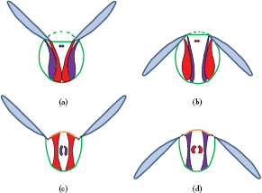
Figure 2. Diagrammatic cross section of insect thorax mechanisms for flight. Thorax mechanisms with direct flight muscles: (a) upstroke and (b) downstroke. Thorax mechanisms with indirect flight muscles: (c) upstroke and (d) downstroke. Contracting muscles are depicted in red, the tergum is depicted in orange.
Download figure:
Standard image High-resolution imageAccording to the type of actuators used in current FWMAVs, compliant transmission mechanisms can be divided into two major categories: DC motor-based and smart actuator-based CTMs. Next, the DC motor-based CTMs will be described firstly in the following.
2.2. DC motor-based compliant transmission mechanism
DC motors are the most popular actuators for FWMAVs because they are reliable, versatile, cheap and easily available in the market [4].
Agrawal at the University of Delaware has done an intensive research on the design, kinematic and dynamic analysis, and simulation of FWMAVs that are actuated using DC motors especially regarding the design of the driving system for flapping flight [20–23]. Even though most of their work concentrates on the study of rigid-body transmission systems, attempts that integrate compliant elements into flapping mechanisms have been proposed. In [20], it presented an energy storage mechanism (shown in figure 3(a)) where linear springs act as elastic energy storage units. When a wing approaches to stop at the end of an upstroke, the two linear springs are fully stretched and the kinetic energy of wings is transformed into elastic potential energy of the spring. During the subsequent downstroke, the potential energy is released. A similar idea appears in [21], with a different mounting location of the springs (see figure 3(b)). The difference between these two solutions is that in the two ends of a linear spring are connected to the base and a wing leading edge in the same side in the first, whereas the second uses a torsion spring to bridge a rocker and the responding wing holder. In addition, Baek et al [24] used a linear spring to directly connect the coupler of the four-bar transmission mechanism and the body frame, as shown in figure 4. According to their experiments, by integrating a linear spring into the flapping mechanism, the average power could be reduced by 30%.
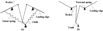
Figure 3. DC motor-based compliant transmission mechanisms using linear/torsion springs. (a) Two ends of a linear spring are connected to the base and the wing leading edge, respectively. (b) A spring is mounted between the rocker of the driving mechanism and its responding wing holder.
Download figure:
Standard image High-resolution image
Figure 4. A 5.8 g flapping mechanism developed at UC Berkeley, in which a linear spring is directly linked the coupler. Reproduced with permission from [24].
Download figure:
Standard image High-resolution imageRecently, coil springs have also been directly coupled with DC motors for directly driving flapping wings toward resonance. Campolo et al [25–27] presented a proof-of-concept flapping-wing micro aerial vehicle shown in figure 5. Their prototype consists of two brushed DC motors, two 7 cm-length wings, two helical springs, and two shaft-spring-wing couplers. The pair of small helical springs is treated as the compliant structures for energy storage and recovery. The two separate DC motors can drive the individual wing to resonate, respectively. Experiments demonstrated the prototype can successfully lift off and the maximum lift-to-weight ratio can be achieved at the flapping frequency 10 Hz. A similar principle is presented in [28, 29].

Figure 5. The prototype of a motor-driven flapping-wing micro aerial vehicle. Reproduced with permission from [27].
Download figure:
Standard image High-resolution imageThe described FWMAVs could lift off and successfully fly, but face a major drawback: the additional springs do not reduce joint frictions energy losses [30], and also add weight. Therefore, structures that combine functions of mechanical parts with elastic energy-stored components [31] seem to be more promising.
The University of Maryland's Small Bird [33, 34] demonstrates a good application of compliant mechanisms in the FWMAV. Figure 6(a) shows the schematic concept of the compliant mechanism for flapping motions. The compliant transmission frame was manufactured as a single piece by using injection moulding. This mechanism reduces the use of traditional joints, lowers the weight of the transmission, decreases the part count, and improves overall efficiency of the transmission. A multi-material compliant mechanism was also developed as driving mechanism for a larger Jumbo Bird [32]. The mechanism is shown in figure 6(b). The miniature hinges were adopted to carry out selective and localized compliance in the multi-material structure, which has been demonstrated to be efficient and feasible for successful flight tests.
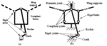
Figure 6. Flapping mechanisms of Small and Jumbo birds. (a) Schematic of the compliant flapping-wing mechanism used in Small Bird. (b) Diagram of compliant mechanism for flapping wing actions of Jumbo Bird. Reproduced with permission from, [32], © Springer-Verlag London Limited 2011.
Download figure:
Standard image High-resolution imageLau et al [30, 35] proposed a similar compliant mechanism, which is shown in figure 7. Lightweight polyimide film hinges, which were chosen as elastic elements to store inertial energy, were integrated into the mechanism. In order to strengthen the stiffness of polyimide film hinges, carbon-fibre reinforced polymer (CFRP) plates were also used in order to build the system. Due to non-linear stiffness characteristic of compliant hinges, the mechanism can abruptly slow down the wings toward the end stroke and subsequently accelerate to reverse the wings. Their research results demonstrated that the compliant transmission mechanism could save almost  power needs when flapping at 25 Hz, compared to a rigid-body mechanism. Furthermore, using the compliant mechanism has led to needing less power to produce the same thrust needed for a full rigid-body mechanism.
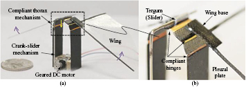
Figure 7. A compliant thoracic mechanism at Nanyang Technological University, in which lightweight polyimide films were integrated into the compliant hinges for elastic energy storage. Reproduced with permission from [30].
Download figure:
Standard image High-resolution imageSimilarly, Sahai et al [36, 37] attempted to integrate flexural hinges into a four-bar compliant flapping transmission for a FWMAV with approximately 3 g of weight. A distinguishing feature of the mechanism is using rubber-based flexures in two of its joints (joints 3 and 4, see figure 8). According to their experiments, not only did compliant mechanism save up to 20% of the input power and 1% of the weight, but also produced more thrust.

Figure 8. The prototype of the Harvard University's FWMAV and its the four-bar transmission mechanism. Note that the rubber flexural hinges are located at joints 3 and 4 while joints 1 and 2 are both rigid joints. Reproduced with permission from [36].
Download figure:
Standard image High-resolution imageTable 1 shows a comparison among various DC motor-based FWMAVs that adopted compliant elements into their drive mechanisms. It can be seen that the weight ratios of compliant elements are far smaller than the counterparts of springs. Moreover, the use of compliant mechanisms for driving FWMAVs can save input energies for flight, which to some extent can improve the flight duration and/or available payload of FWMAVs.
Table 1. Comparison among various compliant flapping transmission mechanisms driven by DC motors.
| Group | Wing span (cm) | FWMAV weight (g) | Compliant element | Weight of compliant element (g) | Compliant stiffness | Compliant mass ratio (%) | Maximum power saving |
|---|---|---|---|---|---|---|---|
| Univ. of Delaware | |||||||
| FWMAV [20] | 69 | 46 | Linear spring | — | 375.2 |
— | 56.3% (in torque) |
| Univ. of California, Berkeley | |||||||
| FWMAV [24] | 8 |
5.8 | Linear spring | 0.259 |
140 |
4.5 | 30% |
| Carnegie Mellon Univ. | |||||||
| FWMAV [27] | 14 | 2.7 | Coil spring | 0.12 |
2.83 |
4.4 | — |
| Uni. of Maryland | Compliant | ||||||
| Small Bird [33, 34] | 33 | 12.8 | segments | 0.01 |
0.034 |
0.08 | — |
| Univ. of Maryland | Compliant | ||||||
| Jumbo Bird [32] | 63.5 | 72.5 | joints | — | — | — | — |
| Harvard Univ. | Rubber | ||||||
| FWMAV [36, 37] | 12.4 | 3 | strips | 0.02 | 3.2 |
0.6 | 20% |
| Nanyang Technological Univ. | Polyimide film | ||||||
| FWMAV [30] | 10 | 3.51 | strips | 0.066 |  |
1.9 | 31% |
aN m−1. bmNm rad−1. cFor detail information, please refer to [30]. dEstimated for four 17.5 mm-length, 0.89 mm-width and 1.52 mm-depth compliant segments, made of ABS material. Such material has a Young modulus of 2.3 GPa, and a density 1040 kg m−3.
2.3. Smart actuator-based compliant transmission mechanism
When the sizes of flying robots fall into millimeters or even micrometers scales, the efficiency of conventional DC motors will substantially reduce. Furthermore, low friction pin joints are not feasible. Compliant mechanisms therefore become a natural solution for designing micro aerial vehicles. Considering the advancement in micro-electro-mechanical systems (MEMS) technology, developing complex and reliable micro-structures becomes possible. Having new technologies for materials will also allow producing lightweight and controllable actuators. Many different kinds of alternative smart actuators have been suggested for flapping-wing MAVs.
A smart actuator is a micro mechanical device that generates motion using smart materials. Table 2 shows the main characteristics of the commonest smart actuators in terms of maximum free strain, maximum stress, deformation energy density, efficiency, and relative speed of response. As shown in the table, shape memory alloys (SMAs), shape memory polymers (SMPs), electrochemo-mechanical conducting polymers (EMCPs), thermal actuators, mechano-chemical polymers (MCPs) can undergo large free strains and exhibit large blocking forces, but have slow response and limited efficiency, which make them not suitable for actuating a FWMAV. In contrast, piezoelectric actuators exhibit a relatively lower free strain. They are capable of producing very high blocking forces and more efficient sensitivity. Due to speed requirements, piezoelectric, dielectric elastomer, electrostatic, electromagnetic actuators are valid alternatives for FWMAVs.
Table 2. Overview characteristics of smart actuators. Source: [38].
| Actuator type | Maximum strain (%) | Maximum pressure (MPa) | Specific elastic energy density(J g−1) | Maximum efficiency (%) | Relative speed (full cycle) |
|---|---|---|---|---|---|
| Dielectric elastomer | |||||
| (Acrylic) | 380 | 7.2 | 3.4 | 60–80 | Medium |
| (Silicone) | 63 | 3.0 | 0.75 | 90 | Fast |
| Electrostatic | 50 | 0.03 | 0.0015 | >90 | Fast |
| Electromagnetic | 50 | 0.10 | 0.003 | >90 | Fast |
| Piezoelectric | |||||
| (Ceramic(PZT)) | 0.2 | 110 | 0.013 | 90 | Fast |
| (Single crystal(PZN-PT)) | 1.7 | 131 | 0.13 | 90 | Fast |
| (Polymer(PVDF)) | 0.1 | 4.8 | 0.0013 | 80 est. | Fast |
| Shape memory alloy (TiNi) | >5 | >200 | >15 | <10 | Slow |
| Shape memory polymer | 100 | 4 | 2 | <10 | Slow |
| Thermal (expansion) | 1 | 78 | 0.15 | <10 | Slow |
| Electrochemo-mechanical conducting polymer | 10 | 450 | 23 | <5% est. | Slow |
| Mechano-chemical polymer | >40 | 0.3 | 0.06 | 30 | Slow |
Generally, smart actuators are integrated into compliant mechanisms and driven at their resonant frequency. Running at resonance can reduce inertial costs of acceleration and deceleration in the wings and will thereby improve efficiency in energy usage for FWMAVs [24]. Currently, the types of smart actuators that have been used together with the compliant transmissions towards resonance can be generally sorted into three categories, including piezoelectric actuator [12, 39, 40], electromagnetic actuator [41, 42], and dielectric elastomer actuators [43, 44]. In the following sections, a review of compliant transmission mechanisms for FWMAVs will be carried out according to the types of smart actuators used for driving.
2.3.1. Piezoelectric actuators
Piezoelectric actuators are devices that make use of an inverse piezoelectric effect [40]. The driving voltage for piezoelectric actuators normally ranges from tens of volts to hundreds of volts. For example, popular monolithic stack actuators are available in voltage ratings from 60 V to 200 V; for high-voltage discrete stacks actuators, their operating voltages ranging from 500 V to 1000 V are typical; the working voltage for the RoboBee mentioned below varies between 150 V and 300 V [45].
When coupled with mechanical transmission subsystems, the actuator can be capable of enhancing stroke amplitudes and reciprocating motions required for flapping flight [42]. Piezoelectric actuators offer high displacements, fast response [46, 47] and high efficiency levels at high actuation frequencies [48]. Therefore, piezoelectric actuators are frequently used for producing insect-scale flying robots.
Mateti et al [12, 49, 50] developed an insect-scale air vehicle called LionFly, shown in figure 9, whose compliant flapping mechanism was manufactured monolithically from an epoxy-based negative photoresist (SUEX) dry film. The prototype, with a mass 112 mg was actuated by a PZT-5H bimorph actuator. Its resonant flapping frequency ranges approximately from 47.5 to 50.5 Hz. The maximum amplitude for flapping can reach 75°. A lift to weight ratio of 1.5 was achieved by the prototype.

Figure 9. Robotic flying insect Lionfly at Pennsylvania State University. (a) Conceptual drawing of the LionFly. (b) A prototype LionFly with zoomed inset showing an end view of the flapping mechanism and actuator. Reproduced with permission from [50], © IOP Publishing Ltd. All rights reserved.
Download figure:
Standard image High-resolution imageSitti [39] has researched on piezoelectric actuators to drive a micro mechanical flying insect for stroke amplification. The piezoelectric materials, soft PZT and single crystal PZN-PT piezoelectric ceramics were used for fabricating the actuator. The piezoelectric actuator treated as a flexible part was compacted in a four-bar thorax mechanism as input link. The prototype of the compliant four-bar structure was made using laser micro machining and folding techniques. The stroke amplification of around 20–25 is achieved by the piezoelectric actuator-based four-bar mechanism. The wing can resonate at 29 Hz with around 90° flapping motion.
Arabagi et al [46] developed a spherical four-bar transmission mechanism actuated by a bimorph piezoelectric bending actuator driven in a quasi-static manner. The piezoelectric actuator was made of two unidirectional M60J ultra-high-modulus carbon fibre layers sandwiched between two PZT-5H piezoelectric sheets. A passive extension out of two S-Glass layers was used for increasing the actuator stroke. A working prototype was manufactured via the smart composite microstructures technique to test and characterize the robot's lift production capabilities and the scaling law of the design with decreasing size. In [51], the authors presented a tool for designing flapping wing mechanisms using piezoelectric bending actuators.
Finally, Wood et al at Harvard University [45, 47, 52–55] have carried out intensive studies on an insect-scale flapping robot, called RoboBee, using a piezoelectric actuator. RoboBee was the first robotic insect capable of lift-off. The authors presented an innovative insect-scale robotic thorax design that is capable of producing an asymmetric wing kinematics that is similar to those observed in nature and used by two-winged insects in order to maneuver. Inspired by the thoracic mechanics of insects, a piezoelectric actuator has been fabricated as a bending bimorph cantilever actuator. The transmission maps the approximately linear motions of the actuators into flapping movements of wings. The transmission consists of links and joints with geometries designed to maximize the product of stroke amplitude and first resonant frequency, given that the actuator and airfoil properties are known. The insect-like robot, shown in figure 10, is capable of flapping at 110 Hz. Actuators are created by laminating two piezoelectric plates (PZT-5H from Piezo Systems, Inc.) to a carbon fibre spacer and electrode layer. The airframe and compliant transmission are created by layering a  m polyimide film with carbon fibre face sheets.
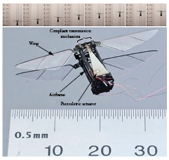
Figure 10. Harvard RoboBee driven by piezoelectric actuators. Reproduced with permission from [53], © IOP Publishing Ltd. All rights reserved.
Download figure:
Standard image High-resolution image2.3.2. Electromagnetic actuators
Electromagnetic actuators transform electrical and mechanical energy into each another by using the electromagnetic-mechanical principle. Electromagnetic actuators have a fast response, simple structure and are easy to control [56]. Having very low voltage requirements is an advantage for using electromagnetic actuators. Their driving voltages can vary from 0 to 24 V [57].
Dargent et al [41] presented a flapping structure concept at insect-scale based on MEMS technologies, which was actuated by a linear electromagnetic actuator. Based on this, Meng et al [56] made a prototype FWMAV with 3.5 cm wingspan and 144 mg weight (figure 11). Flexure hinges are used for occupying the gap between thorax and tergum [41] in order to avoid the energy loss and structure shocks. Two wings were also integrated in the prototype. According to the tests, the maximum flapping resonance frequency was 150 Hz.
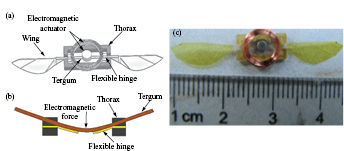
Figure 11. A 3.5 cm wingspan, 144 mg weight prototype actuated by an electromagnetic actuator. (a) Top view of the structure. (b) The variation of wing' stroke with the effect of the electromagnetic force. (c) The physical prototype. Reproduced with permission from [56], © Springer-Verlag 2011, with permission of Springer.
Download figure:
Standard image High-resolution imageFinally, Deng et al [42, 57, 58] recently used a new electromagnetic actuator weighing 2.6 g to drive an insect-scale flapping-wing MAV at its resonant frequency. The electromagnetic actuator mainly consists of a single electromagnetic coil, a permanent magnet rotor, and a virtual spring magnet pair. Wing kinematics and mean lift measurements from the prototype demonstrated a lift-to-weight ratio grater than one at 24 V. This framework was then extended to investigate the feasibility of the proposed actuator at different scales, predicting lift-to-weight ratios well above one for a wide range of the parameter space. Note that, strictly speaking, this kind of electromagnetic actuator cannot be regarded as a compliant mechanism according to the definition of compliant mechanism given by Howell in [11], because they lack flexible components. The permanent magnets used in the prototype were attached to the perimeter of the coil to form a spring effect [57]. These 'virtual' springs created a restoring torque on the rotor when displaced from a neutral position, which is extremely similar to an equivalent joint (a revolute joint with a virtual spring) of a compliant joint in behaviour according to the PRB theory proposed in [11].
2.3.3. Dielectric elastomer actuators
Dielectric elastomers(DEAs) are polymer materials with compliant electrodes that have a large electromechanical response to an applied electric field [38]. DEAs normally operate at very high voltages (∼1–10 kV), whose electric field is around 100 MV m−1 [59, 60]. They can produce large actuation strains at high work density.
In 2002, SRI researchers [61] conceived a thorax-type design using dielectric elastomers for a small flapping wing vehicle. Their research has shown that power densities of the silicone or acrylic elastomers used for driving flapping mechanisms could produce forces enough for lift-off. However, the structural support needed for actuators dramatically lowers the total power density because only 10–20% dielectric elastomer film could be activated by the support structure.
In [43], the use for DEAs to drive an approximately 500 g flapping-wing air vehicle is described. This prototype showed limitations in scaling up the muscles to the power levels required for higher vehicle weight. Moreover, it was limited by the unavailability of batteries and microelectronics that could efficiently deliver the high voltage needed to drive the muscles.
In order to reduce the mass of the support structure and improve the overall work density of DEAs, Lau et al [44] designed and developed a lightweight shell using a cross-ply laminate of carbon fibre reinforced polymer as a support shell structure to pre-strain a rolled DEA. A CFRP shell and a rolled DEA were integrated in an insect-inspired thoracic mechanism, which is shown figure 12. Research results showed that CFRP shell could achieve up to 35% axial pre-strain to a rolled DEA. Furthermore, the structure could provide much higher of the maximum work density than the counterpart with spring rolls.

Figure 12. Integration of a CFRP shell and rolled DEA with a thoracic mechanism to form an insect-inspired wing flapper. Reproduced with permission from [44], © IOP Publishing Ltd. All rights reserved.
Download figure:
Standard image High-resolution imageTable 3 shows the primary features of the prototypes reviewed in this section. As it can be observed form the table, most of current insect-scale FWMAVs are driven by piezoelectric actuators. Even though electromagnetic and dielectric elastomer actuators were adopted to actuate the FWMAVs, no evidences show that those developed prototypes can successfully lift off. Recently, an electrostatic actuator has been presented for artificial insect wings [62, 63]. Such actuator consists of fixed electrodes and moving electrodes. The lift test of the artificial insect wing is presented in [62]. The actuator works at a resonant frequency of 50–70 Hz excited by a DC power source with a voltage varying from  kV, without using any other complex AC circuits.
Table 3. Comparison among various compliant flapping transmission mechanisms driven by smart actuators.
| Group | Wing span (cm) | MAV weight (g) | Actuator type | Compliant element | Compliant stiffness | Resonant frequency (Hz) |
|---|---|---|---|---|---|---|
| Pennsylvania State Univ. LionFly [39] | 7.2 |
0.112 | Piezoelectric actuator | SUEX film | 26.8–107.4 μNm rad−1 | ∼50 |
| Carnegie Mellon Univ. FWMAV [46] | 3.7 | 0.16 | PZT bimorph actuator | PZT bimorph actuator | 219 N m−1 | 37 |
| Harvard Univ. RoboBee [45, 47, 53] | 3 | 0.06 | PZT bimorph actuator | PZT bimorph actuator | — | 110 |
| Shanghai Jiao Tong Univ. FWMAV [56] | 3.5 | 0.143 | Electromagnetic actuator | SU-8 film | — | 120–150 |
| Purdue Univ. FWMAV [42, 57, 58] | 9–14 | 5.2 |
Electromagnetic actuator | Virtual spring | 0–5.64 mNm rad−1 | 30–71 |
| Nanyang Technological Univ. FWMAV [44] | 13 |
10.5 (without electrical devices) | Dielectric elastomer actuator | CFRP shell | 102 |
5–10 |
aEstimated from an image of the LionFly's conceptual drawing in [50].
bEstimated based on two actuators and each one is with a wing.
cCalculated using 2× wing length +  CFRP shell width =
  cm +
cm +  cm.
dCFRP shell contributes one quarter of the total axial stiffness, 408 N m−1 [44].
cm.
dCFRP shell contributes one quarter of the total axial stiffness, 408 N m−1 [44].
2.4. Further readings
Mayo et al [64] made a comparison on the aerodynamic efficiency between hover-flight FWMAV and micro helicopters. The stability of different aerodynamic flapping wing models was analyzed in [65]. Recently, Ward et al [2] explored the potential future directions for FWMAVs from technical literatures that were published from 1984 to 2014. Finally, research challenges on FWMAVs are presented in [66, 67].
3. A design optimization methodology for compliant flapping mechanisms
As shown in former sections, researchers in the FWMAV field have done many remarkable works on the design of compliant flapping mechanisms. However, very few of them have mentioned the details of modelling and optimization design. In [13], we proposed a method named PRBVW. Such method combines the PRB theory and the principle of virtual work so as to design and analyze the behaviour of compliant transmission mechanisms for a FWMAV. This approach has been applied in order to optimize primary attributes at compliant joints (i.e. the torsional stiffness of virtual spring and the initial neutral angular position) for a bat-inspired FWMAV, which is shown in figure 13.

Figure 13. A bat-inspired flapping-wing micro air vehicle (BatBot 2) at Technical University of Madrid. (a) The CAD model of BatBot 2. (b) The sketch of the compliant transmission mechanism for BatBot 2.
Download figure:
Standard image High-resolution imageMinimizing the peak input torque required from a driving motor to avoid undesired shocks that could threaten the stability of flight was our objective. Compared to other optimization methods proposed (see, e.g. [20, 68]), our method is suitable for pseudo-rigid models since internal interaction forces do not need to be considered. Furthermore, the elastic potential energy stored in the compliant joints can be easily taken into account. PRBVW consists of six steps: PRB equivalence, kinematic analysis, aerodynamic modeling, virtue-work calculation, optimization design and final physical test and verification. The detail work process of PRBVW written in pseudo code is shown in algorithm 1. It assumes a rotational actuator (DC motor) used for flapping (see figure 13(b)), but it can be generalized to other compliant transmission mechanisms. We refer to [13] for the mathematical details of the method.
Algorithm 1. Pseudo code of PRBVW.
1. PRB equivalence
|
2. Kinematic analysis
|
3. Aerodynamic modeling
|
4. Virtual-work calculation
|
5. Optimization design
|
6. Test and validation
|


4. Open challenges associated with compliant flapping systems
The introduction of compliant transmission mechanisms into FWMAVs brings a number of benefits and advantages. However, some challenges in developing this kind of flapping mechanism are still open.
- Complaint transmission mechanisms: design, fabrication and controlOne of the biggest challenges is the difficulty of analysing and designing compliant transmission mechanisms. Finite element methods are the widely used to analyse compliant mechanisms. Current commercial software has the capability of analysing the large, non-linear deflections often associated with compliant mechanisms. The general nature of the method makes it applicable for a wide range of geometries, materials and applications. Topology optimization is often integrated with finite element methods to consider many possible ways of distributing material with the design domain [71]. This has the potential to find better designs that would be beneficial for flapping transmission mechanisms. In the previous section, we have proposed a methodology that combined the PRB theory [11] and the principle of virtual work for design and optimization of CTMs, which we believe is useful for future designs of FWMAVs.As for the manufacturing of such small systems, much progresses have been made in advanced fabrication techniques like laser micro machining [72], surface micro machining [73], and polymer micro machining [74]. The latest advances in 3D printing technology allow manufacturing components with the needed mechanical characteristics and printing resolution that can speed up the development of FWMAVs. Using the 3D printing technology, the structure arrangement of the compliant joints will be isotopic rather than homogenous [75]. Hence, new theoretical models and modelling approach will be needed to predict the stiffness characteristic of the compliant structure. The advancement in material science will be crucial since this advanced technology requires new material that can be actuated while providing necessary strength and stiffness to the overall structural integrity. Most importantly, the new material engineered must have high endurance limit and predictable fatigue life.Furthermore, the control of compliant transmission mechanisms for flight is a key topic that hardly appear in the literature. Recently, Kern et al [76] proposed a robust method to control compliant mechanisms with large deflections. In their work, flexure hinges were equivalent to pseudo rigid-body systems with uncertainty. Then, by synthesizing current available theories of multi-body dynamics, a robust controller was employed to control a leaf-spring-type flexure hinge to deflect. Similar ideas appeared in the control of compliant-mechanism-based manipulators, where sliding control [77] and feedback linearization [78] were adopted for positioning of the manipulator, respectively. These approaches could provide us some inspirations for controlling CTMs of FWMAVs. Combining the aforementioned analysis and design approaches of compliant mechanisms, existing multi-body dynamic theories and control methodologies will be essential for the control of compliant transmission mechanisms. The precise position control of CTMs is also one of the most important issues that need to be solved for guaranteeing CTMs produce the desired trajectories and motions. This is a similar problem as in compliant manipulators [77, 78], so this field may provide good literature for CTMs position control.
- Compliant actuators: batteries, on-board power electronics, and selectionCurrently, one of the main limitations of compliant actuators is the power system (including batteries and on-board power microelectronics), especially for smart actuators-based transmission systems used for FWMAVs described in section 2.3. As described before, for most smart actuators, except electromagnetic ones, high voltages are needed in order to produce sufficient forces or displacements. Unfortunately, current compact energy sources suitable for flapping-wing micro robots, like conventional batteries, ultra-capacitors [79], solar cells [80] and fuel cells [81], only generate output voltages below 5 V. Connecting such elements in series does not seem to be practical due to packaging overhead [45]. Lithium polymer batteries are the only commercially available technology that can satisfy the requirements of flapping MAVs at present. As new technologies of batteries are emerging, including micro solid oxide fuel cells [82], lithium batteries with silicon nanowire anodes [83], and lithium air batteries [84], the battery problems faced by smart actuators, perhaps, could be solved in the future.Considering the current voltage problems of batteries, some researchers attempted to design the interfaces of micro power electronics that are capable of converting a low input voltage from an energy source into a time-varying, high-voltage drive signal for powering smart actuators. Karpelson et al [85] presented a sub-100 mg high-voltage power electronic converter for piezoelectric microrobots. After optimization, the converter could output voltages of 200 V at a 3.7 V input voltage, typical of lithium polymer batteries. The applicability of the drive circuits was verified on a flapping wing robotic insect. Some other attempts of electric interfaces for piezoelectric actuators could be found in [86–88]. As for DEAs, Chen et al [89] proposed a power electronic interface with light weight, high power density and high step-up conversion ratio, for driving bimorph dielectric elastomer actuators at low frequency. Through their experimental validations, the dual-stage topological circuit could drive a 600 V DEA at 4 Hz. Even through the circuit could drive DEAs at low frequency, the high operation voltage of 600 V is still a huge obstacle that prevents DEAs from widely applying to micro flying vehicles.Besides the common power problem for compliant actuators, limitations and potential performance trade-offs for each kind of actuator are also required to consider. Piezoelectric actuators have a limited travel range and non-linear displacement characteristics, but they can deliver very high driving force and bandwidth, which makes them potential selections for micro- to macro- scale compliant actuators. As the size increases from macro-scale onwards, electromagnetic actuation can be an alternate solution to the piezoelectric actuators. In general, electromagnetic actuators adopt two types of techniques, i.e. the solenoid actuation and the Lorentz-force actuation, to realize the driving motion. Solenoid actuators may have the advantage of large force-to-size ratio while the Lorentz-force actuator has linear characteristic and large travelling range. Comparing to piezoelectric actuators, a disadvantage of electromagnetic actuators is that, they lack the capability of providing an additional non-actuation stiffness when power-off. As for DEAs, the low stiffness of dielectric materials is a significant design challenge for actuation and power generation for FWMAVs. Much more information on the actuator selection, power electronics topologies and circuit component fabrication options can be referred in [48, 90].
- Compliant wingsIn nature, flying animals are capable of maneuvering using flexible wings, which can deform significantly with effects of both the driving motion of the structure and the aerodynamic loading of the fluid surrounding wings. Compliant wings, within certain limits, appear to be beneficial for both generating favourable aerodynamic and power performance and storing mechanical energy. Given the flight characteristics of wings, compliant aerodynamic structures were brought into the fabrication of wings for FWMAVs. In [91], Mueller et al introduced a successfully flying miniature air vehicle whose wings were fabricated with one-way compliant mechanism for realizing the folding style like large birds. In [92, 93], Wissa et al presented an ornithopter in which the leading edge spars of wings were made of compliant spines. Flight test results revealed that incorporating compliant spines into the leading edge spars of wings can lower the positive acceleration at the body's center of mass and the reduced values are translated into overall lift gains. Recently, a novel self-organized microwrinkle membrane concept for flexible wings was proposed by Tanaka et al [94] inspired by bird feathers and the corrugations of insect wings. The wing is made of carbon fibre-reinforced plastic (CFRP) frames and a polymer film with microscale wrinkles. The wrinkle film wing is mounted on the rigid wing frame and it can passively morph with an effect of aerodynamic force. At present, the compliant wings adopted in FWMAVs are only passively deformable, without the capability of active adjustments. In such case, how to make compliant wings produce synchronous movements under complex and unstable airflow environment and thereby generate stable forces for fight is a big challenge for research. In addition, active morphing-wing concepts were proposed by researchers (see, e.g. [95–99]) for improving efficiency and manoeuvrability. However, the accompanying problems associated with actively morphing wings, e.g. much more complex morphing-wing structures and control systems, have not been solved yet.
5. Conclusions
In this paper, bio-inspired representative designs of compliant transmission mechanisms for flapping-wing micro aerial vehicles are presented. A detailed survey has been conducted on various FWMAV prototypes. Based on the type of actuators, the compliant transmission mechanisms can be classified into two main categories, DC motor-based CTMs and smart actuator-based CTMs. MAVs of each category have been compared in order to explore research trends. In addition, an optimization method for designing FWMAV compliant mechanism is also explained in this paper.
As mentioned before, even though a lot of progress has been achieved on flapping wing micro aerial vehicles through persistent effort from researchers, one of the primary constraints that prevents FWMAVs from being effective in civil application uses is its total length of flight time that continues to be very short. Nonetheless, recent advances on new power storage technology have been able to better shortage in flight time. Furthermore, applying energy-saving mechanical designs in the transmission mechanism and wing structure of a FWMAV is an efficient way to prolong flight time.
This paper has shown how compliant mechanisms inspired by thorax structures of insects are used, as well as how energy consumption for flapping flight can be reduced. Other mechanisms for energy savings can be also found in flying animals. For instance, a budgerigar can shift its wing profile between flapping and gliding, as well as between low and fast speeds during cruise flight [100]. Bats also adopt morphing wings strategies that allow changing wing geometry for maneuvering as well as flight efficiency purposes. In [96, 101] we demonstrated that such mechanism can be imitated in order to improve the bio-inspired FWMAV flight performance. Our recent work on a bio-inspired FWMAV with a compliant flapping mechanism and morphing wings is based on this perspective.
Understanding energy-saving performance of biological systems, and developing high energy-efficiency structures that could leverage natural design will be key factors in order to increase FWMAVs autonomy and payload capabilities.
Acknowledgment
The work of the first author has been sponsored by the China Scholarship Council(CSC). This work has been co-funded by the RoboCity2030-III-CM project (Robotica aplicada a la mejora de la calidad de vida de los ciudadanos. fase III; S2013/MIT-2748), funded by Programas de Actividades I + D en la Comunidad de Madrid and co-funded by Structural Funds of the EU. Finally, we would like to thank anonymous reviewers for their thoughtful comments that were helpful for improving this paper.