


Abstract
The SOLPS-ITER code is utilized to analyze the boundary plasma associated with a fast-flow lithium (Li) divertor configuration in the fusion nuclear science facility (FNSF) tokamak and identify operational regimes with acceptable divertor and core conditions. Plasma transport from the SOLPS-ITER code has been coupled with a liquid metal (LM) MHD/heat transfer code to model a Li open-surface divertor design and assess its impact on the scrape-off-layer (SOL) and core plasma performance. Simulations with only Neon (Ne) impurity seeding have been conducted to evaluate its impact on meeting FNSF design demands for the divertor and upstream plasma parameters. Simulation results indicate that Ne seeding significantly mitigates divertor heat flux but potentially reduces both upstream electron and main ion density due to fuel dilution. The combined application of Ne seeding and deuterium (D2) puffing is required to satisfy the FNSF design requirements on upstream density ( ∼1× 10²⁰ m−3) and divertor energy flux (
 10 MW m−2). D2 puffing plays a role in counteracting upstream density drops and augmenting energy and momentum losses through atomic and molecular processes.
The inlet Li flow velocity is systematically varied across a wide range to identify acceptable flows and corresponding LM surface temperatures. This comprehensive analysis identifies the acceptable Li flow parameters, LM surface temperature, and emitted Li fluxes necessary to meet the major design constraints. The emitted Li fluxes exhibit minimal impact on the main plasma at surface temperatures up to approximately ∼525 ∘C, corresponding emitted Li fluxes of up to φLi ∼2 atoms s−1. Uncertainties in the Li emission processes from the surface are also investigated, primarily influencing Li loss in the lower surface temperature range (
 C), with simulation results indicating a minor impact on the divertor and upstream plasma. Conversely, evaporation predominantly drives the Li loss processes at higher surface temperature ranges (
 C), contaminating both the divertor and upstream plasma.
Export citation and abstract BibTeX RIS

Original content from this work may be used under the terms of the Creative Commons Attribution 4.0 license. Any further distribution of this work must maintain attribution to the author(s) and the title of the work, journal citation and DOI.
1. Introduction
The fusion nuclear science facility (FNSF) is a nuclear fusion reactor design concept [1–4], characterized by an aspect ratio (A) of 4 (major radius R/minor radius a = 4.8 m/1.2 m) with a target fusion power of 500 MW. A critical challenge in the successful operation of a fusion reactor is managing the extreme heat and particle fluxes to the plasma-facing components (PFCs). Several empirical scaling models and theoretical predictions suggest that the fluxes will strike the armored divertor area over a very narrow toroidal strip [5, 6]. Tungsten (W) is considered a leading candidate for solid PFCs and is planned for use in the ITER divertor, however, the maximum allowable energy flux for W is on the order of 10–20 MW m−2 [7]. Additionally, mitigating sputtering to achieve an acceptable component lifetime requires reducing the electron temperature to below few eV [8, 9]. The intrinsic impurities produced during plasma-material interactions (i.e. erosion of the W) can potentially affect the nuclear reaction processes in the core through radiation and dilution. Due to the high atomic charge (Z = 74), W cannot be allowed in the core plasma at concentrations above ∼10−4 [10].
The detached divertor plasma regime represents a potential approach to control the substantial incident plasma heat and particle fluxes to the divertor. Extrinsic gas seeding with large radiation efficiency impurities (such as Ar and Ne) can be used to mitigate the divertor power through enhanced radiation. However, this approach may lead to contamination of the upstream plasma, and a reduction of the upstream plasma density due to core dilution and by reducing the power available for ionization of recycled fuel ions [7]. The mitigation of plasma heat and particle fluxes on the divertor plate while maintaining good core confinement continues to be a major challenge to the successful operation of a fusion reactor.
The use of liquid metal (LM) lithium (Li) offers significant benefits for PFCs owing to its low atomic number (Z = 3), low viscosity, high thermal conductivity, self-healing capabilities through liquid flow, and potential benefits to confinement under controlled Li concentration in the upstream via reducing recycling flux (D sticks on LM surface). Reduced recycling increases plasma temperature, resulting in improvements in core performance, as demonstrated in the [11–17]. Liquid Li can be used in various ways as a PFCs; it may be injected as a fast-flowing layer [4], employed as a gravity-driven system [18], utilized as a  driven [16] or Thermoelectric MHD flow system [19], or applied as an evaporative system known as a 'vapor box' [20, 21]. The application of liquid lithium divertor has demonstrated effective heat flux reduction in NSTX [22]. Continuous flow of liquid Li prevents damage to the LM surface during plasma transients (such as ELMs and disruptions) and steady-state operation [23, 24]. Additionally, the emitted fluxes from the LM surfaces can mitigate divertor heat flux through vapor shielding [25, 26]. Despite these advantages, numerical simulations to evaluate the impact of Li dissipation processes on the main plasma are currently limited. Our objective is to investigate the effects of Li dissipation processes under realistic geometry and conditions relevant to the FNSF.
The emitted Li fluxes from an LM surface are determined by both the incident plasma flux and the surface temperature. The emitted fluxes are from evaporation and sputtering processes, with the latter enhanced by loosely bound ad-atoms [3]. Evaporation and ad-atom loss rate vary as a function of LM surface temperature, while the surface temperature is determined by the Li LM flow velocity and incident energy flux. Consequently, understanding and mapping Li flow velocity and surface temperature ( ) is required for predicting evaporation and ad-atom processes.
Several factors must be considered to identify operating windows in terms of flow velocity and surface temperature for a given LM divertor geometry that are consistent with the requirements on the incident plasma energy flux and core plasma quality. The LM surface temperature must be kept higher than 200 ∘C (Li melting temperature: 180 ∘C), as Li should flow through the whole circulation loop [4]. The emitted Li fluxes from an LM surface interact with the main plasma and can transport Li to the plasma-confined region, potentially contaminating the core fusion reactions. Despite Li being a low-Z material, high concentrations of Li in the core will significantly dilute hydrogenic species, diminishing core fusion performance. In this paper, we aim to identify the upper limit of the Li sourcing rate (i.e. the surface temperature of the flowing LM) compatible with both the core and divertor plasmas.
The impact of Li sourcing was previously investigated using a Li sourcing model with a uniform radial profile in [27]. In this work, we explore the effects of Li sourcing with a more realistic profile to identify an acceptable solution for FNSF. A fast-flowing open-surface configuration is modeled by coupling the boundary plasma transport code SOLPS-ITER [28–30] and an LM MHD/heat transfer code [31]. This coupling allows us to conduct scrape-off layer (SOL) and divertor simulations, integrating flowing liquid metal fluid behavior with near-surface physics.
The primary objective of this work is to find an LM divertor solution that aligns with the FNSF design requirements, specifically the peak divertor heat flux (
 10 MW m−2), upstream Li concentration (1.7
 ), and electron density at the outboard-midplane (OMP) (
 ∼1×10²⁰ m−3), as well as to explore the physics of a fast flow liquid Li divertor. A critical component of this design optimization involves precisely identifying the operating LM surface temperature window.
2. SOLPS modeling setup
The geometry of the SOLPS-ITER (abbreviated to SOLPS) simulation is illustrated in figure 1. SOLPS is an integrated tokamak boundary transport code suite that couples a multi-fluid plasma code 'B2.5' and a kinetic Monte–Carlo code 'EIRENE' which handles neutral dynamics, plasma-neutral interactions, and plasma-wall interactions processes [29, 30]. The current simulation involves 14 fluid plasma charge states (D, Ne, and Li) and 4 neutral species (D2 molecule, D0, Ne0, and Li0). In this work, neutral–neutral collisions are considered via the BGK approximation [32]. The BGK approximation considers collisions between D–D, D2–D, and D2–D2 species only, while neglecting collisions for D–Ne and D–Li. The parallel transport is classical [33] and anomalous diffusive transport is used in the radial direction. The radial transport coefficients ( = 1.0 m2 s−1 and D
 = 0.3 m2 s−1) are assumed to be the same for all ion species. These transport coefficients are selected to match values used for the majority of the ITER simulation database [7], and result in a heat flux width of ≈ 3–4 mm at the OMP.
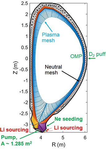
Figure 1. Schematic view of simulation setup with gas puffing locations.
Download figure:
Standard image High-resolution imageD2 gas fuelling and Ne seeding locations are positioned at the OMP and outer divertor, to respectively control the upstream plasma density and divertor energy flux. A zoomed-in view of the outer and inner divertors is illustrated in figure 2 to highlight the locations for gas puffing, pumping, and Li sourcing. Other simulation parameters are set according to the FNSF design from Kessel et al [2, 3]. An input heating power of 150 MW and a particle source of  s−1 are set as core boundary conditions. A pump is designed in the private flux region (PFR) surface to remove neutral particles from the system. The pump has a surface area of 1.285 m2 and an absorption rate of 5
 . The same albedo applies at the pumping surface for atoms and molecules. Li atomic models (radiation, ionization, recombination) are based from the ADAS database [34].
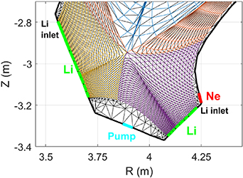
Figure 2. A zoomed-in view of the FNSF divertor region highlighting the source locations. Ne is seeded from the outer divertor, Li is sourced along both the outer and inner divertors based on local plasma conditions (i.e. SOLPS-LM/MHD code coupling), and a pump surface in the PFR to remove neutral particles.
Download figure:
Standard image High-resolution imageThe pumping speed (S) is calculated by the following equation:

Where A is the surface area of the pump (m2), S is the pumping speed (m3 s−1) for particles with temperature T (K) and mass m (AMU), and R is the given recycling coefficient (R sets to 0.95) on the wall surface. Therefore, 1- R represents the sticking fraction (i.e. absorption rate).
Li is sourced through a set of discrete gas puff segments designed along the inner and outer divertor surfaces, as shown in figure 2. The sourcing of Li-neutral atoms into the plasma occurs with a cosine angular distribution and a Maxwellian energy distribution. The value of each Li gas puff segment is given based on the magnitude of the calculated total Li flux, computed using a model described in section 4, adjusted to the area of each puff segment to maintain the total Li flux ( ). The SOLPS simulations are iterated with the MHD/heat transfer calculations. During the iteration process, the magnitude of each Li gas puffing segment was kept constant in EIRENE at every timestep, and the SOLPS ran until the solution reached the steady-state condition. Once the solution reached the steady-state condition, the SOLPS heat flux was used to compute the LM T
 . We also compared this model with an updated Li sourcing model, where Li sources were automatically adjusted in EIRENE at every timestep based on the local plasma parameters. Both models (explained in more detail in section A.2) show similar results for the conditions investigated in this work.
3. FNSF demands on upstream ne
, C
 , and divertor heat flux

The FNSF design requirements are summarized in table 1. The tolerable upstream Li concentration (C
 =
=  ) for FNSF has been estimated following the [2] considering fuel dilution and radiation. Since Li is a low Z material (i.e. lower radiation n
 Lz
C
Lz
C
 ) and is fully stripped in the core, its impact on the core plasma is primarily through fuel dilution. At high C
 core fusion power (P
 ) is reduced as [35, 36]
Table 1. Summary of the requirements of the design based on the [2, 3]. The primary objective of the this work is to identify the acceptable LM surface temperature (Tsurf) based on these requirements, while minimizing the impact of emitted Li fluxes on both core and divertor plasmas. This, in turn, mitigates potential core plasma contamination through fuel dilution. The establishment of this upper limit serves to optimize overall performance and mitigate potential challenges associated with the interaction between the liquid metal and the surrounding plasmas.
 (m−3) (m−3) |
 (MW m−2) (MW m−2) |
c
 ( ( ) ) |
Z

|
n
 /ne
( /ne
( ) ) |
 ( ( ) ) |
 ( ( ) ) |
u
 (m s−1) (m s−1) |
|---|---|---|---|---|---|---|---|

|

| 2.4 | 2.4 | 87 | 1.7 | 0.3 |
 10 10 |


Core fusion power decreases by nearly 12 with 2
 Li concentration contamination. The n
 /ne
ratio of the FNSF design requirement is 87
/ne
ratio of the FNSF design requirement is 87 with allowable core helium (He) concentrations of 2.45
 (corresponds to dilution of 4.9
 ,
,  as of equation (3)) [2]. Therefore, the core
  should be lower than 1.7
 (dilution of 5.1
 ) in the case of 0.3
 Ne concentration (dilution of 3
 ), as shown in table 1. However, the acceptable C
 can be increased to 2.7
 in the cases of no Ne seeding, which clearly indicates the tightness of the operating point for FNSF. The FNSF is designed to operate at a Greenwald density fraction of 0.9 [37].
The impact of Li on core turbulent transport [38] or global transport due to low recycling conditions are not considered here. Lithium Tokamak eXperiment Upgrade (LTX-β) demonstrated that a Li wall can lead to low recycling operation and increased plasma performance due to increased temperature [39]. While D recycling on Li surface is an important area of research, the present study aims at identifying the upper limit of Li in the core to avoid core dilution.
As shown in table 1, the FNSF design goal is to keep the peak surface heat flux below 10 MW m−2 to keep surface temperatures in an operational range with a Li flow of less than 10 m s−1. The necessary Li velocities to mitigate high heat fluxes in the divertor region for an open-surface lithium divertor with a helium-cooled substrate have been detailed in [40].
The relationship between the Li LM T and inlet Li flow velocity for a single-pass coupling procedure is illustrated in figure 3 for two heat flux profiles calculated by SOLPS, corresponding to a low and high Li evaporation rate. The incident energy flux (including plasma heat flux, neutral, and radiation loads) profiles (
 ∼25 MW m−2 and 9 MW m−2 corresponding to without Ne seeding in figure 4 and with Ne seeding in figure 5, respectively) are utilized. The Li LM/MHD code is employed to compute the LM T
 for a given incident heat flux and inlet Li flow velocity. Li T
 rises as Li flow velocity decreases. Elevated speeds (
 15 m s−1) are needed to keep the T
 within an acceptable range (i.e, below 525 ∘ C as discussed in section 4) for higher heat flux cases (
 ∼25 MW m−2); however, comparatively slower speeds (
 7 m s−1) are required for the lower incident heat flux cases (
 10 MW m−2) as the evaporation is a strong function of T
 . The operating window of LM divertor is significantly constrained by LM T
 , which can be reduced by either lowering the divertor heat flux or increasing the Li velocity.

Figure 3. Mapping of an LM peak surface temperature ( ), Li flow velocity, and incident surface heat flux at the outer-divertor. Here, the SOLPS heat flux profiles are used as input to the MHD/heat transfer code to calculate the surface temperature based on the inlet Li flow (i.e. a single-pass coupling result, more specifically, SOLPS computed heat flux is used as an input to the LM MHD/heat transfer code).
  : 9 MW m−2 is the total energy flux at the outer divertor with Ne seeding (see figure 5), while
  : 25 MW m−2 corresponds to without Ne seeding. All subsequent results in this paper correspond to the
  : 9 MW m−2 case, while
  : 25 MW m−2 will be done in the future.
Download figure:
Standard image High-resolution image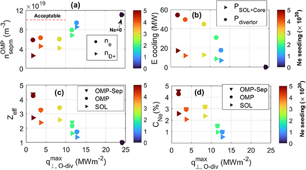
Figure 4. Dependency of (a) electron and main ion density, (b) electron cooling for the core + SOL, and divertor regions, (c) Z , and (d)
  as a function of peak outer divertor plasma heat flux. OMP-Sep represents the magnitude of
  and
and  at the OMP separatrix, OMP represents the mean of
  and
and  radial profile at the OMP, SOL represents the mean of
  and
and  across the entire SOL volume. The acceptable range is defined in [2] and also shown in table 1. The neon (Ne) seeding rates (in atoms s−1) are depicted using a color bar.
Download figure:
Standard image High-resolution image
Figure 5. Radial profile of energy fluxes on the (a) outer divertor and (b) inner divertor in the case of Ne seeding 1 atom s−1 and D2 puffing 4
 atom s−1 (Input to the Li LM MHD code, referred to
  9 MW m−2 in figure 3).
Download figure:
Standard image High-resolution imageThere are concerns regarding liquid Li injection and draining at high velocities ( 10 m s−1), particularly due to issues such as MHD drag in flowing LM within magnetic fields and droplet formation [40–43]. It should be noted that the SOLPS and MHD/heat transfer computations cannot guarantee the establishment of such high-velocity flows in a real fusion device. Fast Li MHD flows under divertor conditions have not been extensively studied either experimentally or numerically in three dimensions (3D), and this needs attention in future research. Moreover, a high Li velocity implies a high Li inventory at the tokamak site, which could pose safety concerns. Given this, here we consider Li flow velocities limited to 10 m s−1 [3]. The divertor energy flux should be limited to lower than 10 MW m−2 to keep surface temperatures in an acceptable range for these flow velocities.
3.1. Scan of Ne seeding rates to reduce divetor heat flux
Ne seeding is used to maintain the divertor heat flux lower than 10 MW m−2 via heat dissipation via radiation. The D2 puffing level is maintained at a constant  atoms s−1 while the Ne seeding condition is varied over a wide range. The simulation results presented in this subsection and section 3.2 with standalone SOLPS-ITER (i.e. without LM MHD/heat transfer code coupling), as the goal of Ne seeding is to first obtain fluxes and baseline conditions which meet the FNSF design requirements listed in table 1.
Figure 4(a) depicts the relationship between the upstream electron density and peak outer divertor plasma heat flux. As Ne seeding levels increase from 0 to  atoms s−1, there is a significant reduction in the peak divertor energy flux. Specifically, Ne seeding levels of 5
 atoms s−1 results in a peak outer divertor plasma energy flux of 1.75 MW m−2. However, it is important to note that Ne seeding reduces the upstream electron and main ion density as well, due to the presence of highly radiating charge states of neon. For the highest Ne seeding level, the upstream electron density is reduced by nearly 50
 .
.
Figure 4(b) shows the dependence of the electron cooling rate on peak divertor heat flux for the divertor and core + SOL, with separate data point shapes to discriminate between the power radiated within the divertor volume and power radiated within the core + SOL volumes. The region definition used in the SOLPS simulation is depicted in figure 1, where blue, orange, yellow, and purple regions correspond to the core, SOL, inner divertor, and outer divertor, respectively. The electron cooling due to Ne dissipation processes (ionization, neutral radiation, line radiation, and bremsstrahlung radiation) is more effective in the divertor (facilitated by the seeding location). At elevated seeding levels, Ne also induces significant radiation in the core and SOL regions, contributing to a decrease in core plasma performance.
Figure 4(c) illustrates the dependency of the effective ion charge (Z
 = (
= ( )/ne
) at the OMP and the entire SOL volume on the outer divertor peak heat flux. Ne concentration is increased as the Ne seeding rate is increased, as illustrated in figure 4(d). While Ne seeding effectively reduces the
)/ne
) at the OMP and the entire SOL volume on the outer divertor peak heat flux. Ne concentration is increased as the Ne seeding rate is increased, as illustrated in figure 4(d). While Ne seeding effectively reduces the  to below 10 MW m−2 through line radiation, this comes at the expense of an unacceptable increase in Z
 .
.
In conclusion, simulations using only Ne starting from a D2 puff level that gives  = 1× 10²⁰ m−3 fail to meet the FNSF requirements for upstream electron density and impurity concentration due to elevated core radiation and dilution. To address this, both the D2 and Ne seeding levels are thoroughly scanned to identify an operating window. The D2 puffing level is increased to counteract the core density drop, while a smaller amount of Ne is used to refine the operating parameters for FNSF, as discussed in the next subsection.
3.2. Identified D2 and Ne seeding window through a set of scans to meet FNSF requirements
SOLPS is employed to identify the puffing and pumping levels that yield acceptable electron density at the OMP separatrix and the peak divertor energy flux. Through an extensive set of scans, it has been determined that a combination of Ne seeding (1 atoms s−1) and D2 puffing (4
 atoms s−1) meets all the FNSF demands on the divertor heat flux (refer to figure 5) and upstream density (refer to figure 6). Ne concentration at the OMP separatrix is found to be around 0.3
 . Ne seeding effectively mitigates plasma heat flux to the divertor through radiation while D2 puffing counteracts the reduction in upstream density. More details can be found in [27].
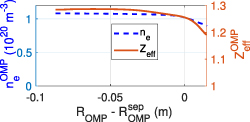
Figure 6. Radial profile of electron density and  at the OMP in the case of Ne seeding 1
 atom s−1 and D2 puffing 4
 atom s−1.
Download figure:
Standard image High-resolution imageFigure 5 shows the radial profile of the total heat fluxes on the outer and inner divertor. Ne seeding significantly mitigates the plasma heat flux (from ∼25 to ∼4 MW m−2) to the outer divertor, resulting in the plasma, neutral, and radiation loads of similar magnitudes. In this work, the radiation heat load was computed in cylindrical approximation using the SOLPS internal tool (WLLD), however, the radiative heat load can also be computed with external tools, as referenced in [44, 45].
The peak energy flux on the inner and outer divertor is found to be lower than 10 MW m−2 (refer to figure 5) while figure 6 shows the radial profile of electron density and  at the OMP, with
  found to be nearly
  m−3 and
  also lower than 2.2, meeting all the requirements listed in table 1. A well-balanced combination of puffing is necessary to maintain plasma parameters in the upstream and in the divertor region. The combined Ne and D2 puffing regime, identified through these scans, is utilized for coupling and detailed analysis involving liquid lithium, as discussed in section 4. The LM surface temperature is calculated based on the deposited energy flux (figure 5).
4. SOL and divertor simulations with the self-consistent coupling between the SOLPS and a Li LM MHD heat transfer code
4.1. Li sourcing model and coupling between SOLPS and LM MHD heat transfer code
LM PFC components introduce new sources of plasma impurities, including physical sputtering, evaporation, and sputtering of loosely bound ad-atoms [3]. The emitted fluxes from an LM surface are calculated based on the equations and parameters outlined in [46]. Figure 7 shows the emitted Li fluxes from an LM surface as a function of T
 . The emitted Li fluxes are calculated according to equation (4). Physical sputtering as considered here is independent of T
 . In contrast, evaporation loss rapidly increases with the T
 , while the ad-atom loss rate also rises with T
 until it largely saturates at temperatures (
 500 ∘C). The basic assumptions and simplifications of the work are as follows: (1) no chemical interactions of D and Ne with the LM surface, (2) pure Li emitted from the surface depending on the local plasma conditions, (3) D and Ne are fully recycled from the LM surface (Li is already 100
 saturated by D), and targets, (4) Li is fully stuck on the wall and targets, (5) Li re-deposition is ignored, and (6) the sputtering yield is not dependent on the local plasma conditions.

Figure 7. Dependence of surface temperature ( ) and emitted Li flux components from an LM (assuming
  = 1024 m−2 s−1).
Download figure:
Standard image High-resolution imageThe total emitted Li flux from the LM surface can be expressed as follows:

Where  , a = 5.055, b = 8023, m
 is the mass of Li atom, T
 is the surface temperature (output of MHD code), α is the sticking coefficient of 1, f
 is the fraction emitted as neutrals and assumed to be 0.35 [46],
  is the incident main ion flux (D) on an LM, Y
 = 10−3,
  = 1, the fitting coefficient (A = 10−7) has been obtained for D+ impinging on liquid Li in PISCES-RF linear plasma device [47], E
 = 0.9 eV,
  = 10−3, and
  is the ad-atom to physical sputtering yield. E
 , where E
 is the ad-atom surface binding energy while E
 is the surface diffusion activation energy [47]. E
 was measured to be 0.75 eV [48]. Significant uncertainties exist in ad-atom binding energy, ad-atom yield, and constant A, as discussed in section 4.2. Compared to [49] we account for uncertainties in the ad-atom yield resulting from physical sputtering. Although Li redeposition may alter the sputtering flux, it might not have a significant impact on the evaporation flux. As a result, we anticipate that Li redeposition may not significantly alter the operating window identified in this work. In the future, we will investigate the impact of Li redeposition.
Self-consistent calculations of the emitted Li fluxes from an LM surface require liquid MHD and heat transfer calculations to determine the T
 given the incident plasma flux. Higher T
 can result in higher emitted Li fluxes, which in turn reduce T
 due to a reduction in the plasma heat flux via Li dissipation processes. Therefore, the SOLPS is coupled self-consistently with an LM MHD/heat transfer code [31] to understand these feedback processes and to find operating conditions consistent with the reactor design scenarios.
The LM MHD/heat transfer code computes the thickness of the Li layer, the flow velocity, and the Li T
 , using the surface energy fluxes (figure 5) computed by SOLPS as input data. A more detailed description of the MHD code is provided in the appendix A.1. A schematic view of the coupling process is shown in figure 8. During the coupling procedure, the inlet flow velocity is maintained constant, while the heat flux profile is computed using SOLPS based on the emitted Li fluxes. The procedure is iterated until convergence is achieved.
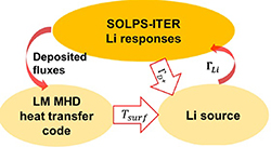
Figure 8. Schematic view of the SOLPS and LM MHD/heat transfer code coupling. Li source block calculates total Li fluxes using equation (4).
Download figure:
Standard image High-resolution image4.2. Constraining uncertainties in Li losses and establishing a physics basis for an LM Li-divertor
Significant uncertainties exist in Li loss processes, such as physical sputtering yield (Y
 ) and ad-atom to sputtering yield (Y
 /Y
/Y
 ). The aim of this section is to understand the sensitivity of total Li loss to these parameters and establish a physics model for an LM Li-divertor. Although higher Y
 significantly increases the physical and ad-atom processes, evaporation loss mainly dominates the total loss processes at higher surface temperature regions (
 525 ∘C). The dependency of Y
 on the incident energy has been calculated and reported in [50]. Y
 due to D+ incident on Li strongly depends on the incident energy, rapidly reducing with the incident energy. SOLPS results have been used in a single-pass coupling to the hPIC code, finding Y
 in the range of 0.001 [46], consistent with the reported data in [50]. Consequently, Y
 = 0.001 is used in this simulation.
Ad-atoms are mobile atoms excited from their bound state on the LM surface by the incident plasma flux but lack sufficient energy to be sputtered from the surface [47]. As a result, ad-atoms require less energy to be emitted from an LM surface. The uncertainties in ad-atom losses arise from factors such as ad-atom yield, surface binding energy, and constant A [3, 46, 47]. The ad-atoms to sputtering yield (Y
 ) covers a broad range; previous experiments and modeling suggest a variation from approximately ∼1–70 [47]. Figure 7 illustrates the dependency of uncertainties in ad-atom losses. When Y
 (referred to Y/Y in figure 7) is 1, the total emitted flux is primarily dominated by the physical sputtering and evaporation flux. However, at higher yields, ad-atoms contribute significantly to Li losses in the temperature range of 200 ∘C–525 ∘C, while evaporation becomes the predominant driver of Li fluxes at higher temperatures (i.e,
  550 ∘C).
Significant uncertainties also exist in ad-atom surface binding energy; PISCES-B data suggested E
 = 0.70 eV [47], leading to a calculated E
 to 1.45 eV (E
 = E
= E
 —E
—E
 ; E
; E
 was measured to be 0.75 eV [48]), which is lower than the surface binding energy of Li (1.67 eV). As ad-atom binding energy increases, ad-atom losses decrease (see figure 7). Ad-atom losses are mostly saturated at the lowest binding energy, implying that lower binding energy primarily affects Li losses at lower surface temperature regions (i.e.
  400 ∘C).
Previous PISCES-B data shows good agreement with the experimental data at A = 6.9 [3, 47]. Ad-atom losses are reduced with an increase in the magnitude of the fitting coefficient A (see figure 7). This constant also affects Li loss processes at the lower surface temperature range.
The Y
 is varied over a wide range (1–100) to understand its impact on the plasma parameters and the sensitivity is studied by SOLPS (refer to figures 16 and 17 in the appendix). Simulation results indicate that Y
 uncertainties show a minor impact on the main plasma (see also figure 17); ad-atom uncertainties only affect Li loss processes at the lower surface temperature regions (i.e.
  525 ∘C) as shown in figure 16, while evaporation flux mostly provides higher Li fluxes and contaminates the main plasma by fuel dilution. Given that the impact of Y
 uncertainties is very small at higher surface temperatures (refer to figure 16), Y
 = 1 is used for the subsequent section. In this work, A = 10−7, E
 = 0.9 eV, and Y
 /Y
/Y = 1 are used for detailed Li sourcing in section 4.3, and all results and discussion in this work are valid based on these assumptions.
Figure 9 presents the calculated LM T
 and corresponding total emitted Li fluxes from an LM surface using equation (4). While maintaining a constant LM thickness of 5 mm, the inlet flow velocity was adjusted to achieve different peak T
 values in order to identify the upper limit of T
 . The emitted fluxes from an LM surface increase with increasing surface temperature. Components of the emitted Li fluxes are shown in the appendix (refer to figure 18). For increasing surface temperature, the evaporation flux is strongly enhanced due to its strong dependency on the surface temperature (see figure 18).
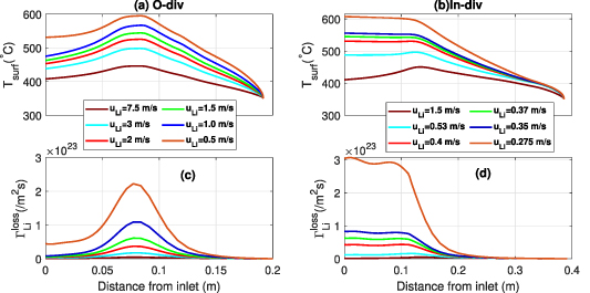
Figure 9. Radial profile of LM surface temperature at the (a) outer divertor, (b) inner divertor, and corresponding emitted Li flux for (c) outer and (d) inner divertor.
Download figure:
Standard image High-resolution image4.3. Identify optimum LM surface temperature in terms of upstream and divertor plasmas
Figure 10 shows the dependency of the radiative power losses due to Li dissipation processes as a function of the peak LM surface temperature. The radiation power loss due to Li dissipation processes shows a weak dependency at the lower surface temperature due to lower emitted Li fluxes. However, the radiation loss is rapidly increased after 525 ∘C (2D profile is shown in the appendix, figure 19), which indicates the contribution of evaporation processes, as evaporation mostly dominates Li loss processes after 525 ∘C (see figure 18). Therefore, Li only reduces the divertor heat flux at the higher T
 range (
 525 ∘C) via radiation. Increasing T
 to 600 ∘C, results in a radiation power loss of 15 MW.

Figure 10. The dependency of the radiative power losses due to Li dissipation processes is shown as a function of the peak LM surface temperature, computed by the SOLPS code. In the case with the highest T
 , the total radiation is approximately 14.5 MW, with lithium neutral radiation accounting for nearly 4.2 MW, and line radiation nearly 10.3 MW.
Download figure:
Standard image High-resolution imageIn this paper, for the sake of simplicity, the peak surface temperature (T
 ) represents the 1st iteration temperature (i.e. figure 3), while the simulation results in section 4.3 correspond to the converged condition results. Figure 11(a) illustrates the relationship between the final and initial condition T
 to understand the extent of temperature change from the initial condition due to Li dissipation processes, thereby illustrating the impact of the coupling feedback process. On the other hand, figure 3 depicts the relationship between T
 at a given Li flow and surface heat flux (single pass MHD code output). The main motivation of the coupling is to understand the dynamics and overall impact of the feedback process. During this process, the emitted Li fluxes reduce plasma heat flux through Li dissipation processes, particularly at low flow rates where low Li flow results in higher T
 and increased evaporation. Consequently, the final iterations yield a lower peak surface temperature compared to the initial conditions (refer to figure 11). This occurs because T
 depends on both the flow velocity and incident heat flux, demonstrating the influence of the coupling process.

Figure 11. The dependency of the (a) LM peak surface temperature at the outer divertor, (b) emitted Li fluxes correspond to the surface temperature, (c) total peak energy flux at the outer divertor, and (d) Li concentration at the OMP separatrix as a function of inlet Li flow velocity.
Download figure:
Standard image High-resolution imageThe higher emitted Li fluxes reduce plasma heat flux via Li dissipation processes at the higher surface temperature region. As a result, the converged case provides a slightly lower peak surface temperature compared to the initial (1st) iteration (see figure 11). We have identified the acceptable Li flow ( 2 m s−1), surface temperature (
 525 ∘C), and Li flux (
 ∼1×10²³ atom s−1, corresponds to 1.118 gm s−1) in terms of upstream Li concentration.
Li concentration at the OMP increases with rising surface temperature (refer to figure 12), and the Li concentration is found to be in the acceptable range when the surface temperature is kept below 525 ∘C. This indicates an upper limit of Li sourcing range, and beyond that sourcing range, Li contaminates the upstream main ion density via fuel dilution. Within the assumptions of this model, an acceptable operating window for an LM Li divertor has been identified.

Figure 12. Radial profile of Li concentration along the OMP as a function of peak LM surface temperature.
Download figure:
Standard image High-resolution imageHigher Li sourcing significantly reduces main ion density due to fuel dilution, while the electron density remains almost similar (the ions are fully stripped), as shown in figure 13. Fuel dilution (1 -  ) results in a 12
 reduction in fusion power by C
 2
2 .
.  is increased slightly with increasing Li sourcing.

Figure 13. The dependency of the (a) electron and main ion density, and (b) Z at the OMP separatrix as a function of peak LM surface temperature.
Download figure:
Standard image High-resolution imageFigure 12 shows the radial profile of Li concentration at the OMP. Lower surface temperature is correlated with lower Li concentration, while higher surface temperature significantly increases Li concentration at the OMP. Li neutrals are confined near the divertor surfaces while Li3+ is distributed over the whole plasma volume at high sourcing levels (see figure 20), reaching up to approximately ∼5% in the core.
Higher Li sourcing leads to plasma detachment by enhancing both energy and momentum losses (indicated by the pressure drop in figure 21). The radial profile of electron temperature at the outer divertor as a function of T
 is shown in figure 22. Combined puffing of D2 (
 atoms s−1) and Ne (
 atoms s−1) is used. The impact of these gases has already reduced T
 to lower than 1 eV at the separatrix at the divertor, while Te
increases in the far SOL. The poloidal profile of Te
along the 3rd flux tube outside of the separatrix is shown in figure 23 to understand electron cooling due to Li in the upstream region. The description of 3rd flux tube can be found in [27]. It is shown that Li electron cooling effects can reduce Te
in the divertor region while showing a minor impact at the OMP (refer to figure 23).
to lower than 1 eV at the separatrix at the divertor, while Te
increases in the far SOL. The poloidal profile of Te
along the 3rd flux tube outside of the separatrix is shown in figure 23 to understand electron cooling due to Li in the upstream region. The description of 3rd flux tube can be found in [27]. It is shown that Li electron cooling effects can reduce Te
in the divertor region while showing a minor impact at the OMP (refer to figure 23).
Total plasma pressure ( ) is strongly reduced at higher T
 on the outer divertor. On the other hand, a slight increase in plasma pressure is shown at the inner divertor when T
 is increased up to 550
  , as electron density is increased due to Li ionization processes. A rollover is shown in electron density, as higher Li sourcing reduces the electron temperature, increasing recombination processes. From the above discussion, Li LM T
 should be limited to 525
  to avoid contamination of the main plasma by Li dissipation processes.
5. Summary
The SOLPS-ITER code has been utilized to analyze the physics of fast-flow LM divertors for FNSF. Ne seeding alone starting from a D2 puff level that gives  fails to achieve the FNSF design requirements due to a higher impurity concentration in the core, while a combination of D2 puffing and Ne seeding successfully satisfies all the FNSF design criteria, as D2 puffing counteracts the upstream density drops and reduces plasma temperature through atomic and molecular processes. A Li LM MHD heat transfer code is self-consistently coupled with the SOLPS-ITER code. Li is introduced into the system based on the LM surface temperature, calculated using the Li flow velocity and incident energy flux to the divertor surfaces. The Li LM operating surface temperature has been identified (
 C), corresponding to a total emitted Li flux (
 atoms s−1) and 1.118 gm s−1. Beyond that temperature range, evaporation becomes a significant driver for Li loss processes, leading to contamination of the main plasma mainly through fuel dilution. Uncertainties in ad-atom processes show a minor impact on the plasma, as these uncertainties primarily affect Li loss processes in the lower temperature region (
 525 ∘C).
In this simulation, Li is fully stuck on the wall and targets. Simulation results indicate that Li ions and neutrals are returned to the wall and targets depending on the sourcing rate: at lower sourcing rates, mostly Li ions are redeposited on the target, while at higher sourcing rates, Li neutrals are returned to the walls, targets, and pump (refer to table 4 and figure 24).
Future studies will explore a self-consistent coupling among SOLPS-ITER, hPIC, and the Li MHD code to calculate sputtering flux and assess the impact of Li re-deposition, recycling, and pumping. In the next step, aiming for a better understanding of the coupling between the boundary plasma and other physics in a tokamak, a 2D Li point source will be introduced in SOLPS as a function of time. This source will represent either Li droplets generated at the open surface of the cooling Li layer and injected into the plasma or will serve as an ablation/ionization source in the case of fuel pellet injection following the approach taken in [51].
Acknowledgments
The authors would like to thank Dr Jae-Sun Park, Dr Lauren Nuckols, Dr Erin Tinacba, Dr Iván Paradela Pérez from ORNL for their valuable suggestions and comments. Useful suggestions from Dr Eric Emdee, Dr Andrei Khodak, and Dr Robert Goldston, PPPL are gratefully acknowledged. Additionally, the authors extend their gratitude to the reviewers for carefully checking the paper thoroughly. This manuscript has been authored in part by UT-Battelle, LLC, and is supported by the US Department of Energy (DOE) Office of Fusion Energy Sciences under Contracts DE-AC05-00OR22725 and DE-AC02-09CH11466. The publisher acknowledges the US government license to provide public access under the DOE Public Access Plan (http://energy.gov/downloads/doe-public-access-plan).
Data availability statement
All of the data generated or analysed during this study can be made available by the corresponding author on reasonable request.
Appendix:
A.1. Mathematical model and computer code for LM MHD open-surface flows with heat transfer
The mathematical model employed in this study for the analysis of open-surface LM MHD flows in a magnetic field along an inclined solid substrate to the horizon, with or without lateral walls including heat transfer is based on the boundary layer (thin-shear-layer) approximation as proposed for this type of LM MHD flows in [52]. In this work, the full 3D fluid flow is reduced to a 2D form using the standard boundary layer approximation [53]. In the case of a segmented design (S1 in equation (9)), the original 3D MHD flow equations are simplified to a quasi-two-dimensional (Q2D) form by integrating them in the direction of the applied (toroidal) magnetic field (z-direction) between the two lateral walls. This simplification is made under the assumption of a Hartmann-type velocity profile in the z-direction. The resulting Q2D flow equations, also known as the SM82 model, were first introduced in [54] for a nonconducting duct (quoted from the [31]). In [55], an attempt was undertaken to expand this model to an electrically conducting duct in the name of the 'averaged flow model'. This averaged flow model is employed in the present study for open-surface MHD flows.
In the present model, the lateral walls are treated as either thin electrically conducting or insulating walls, the choice depending on the wall conductance ratio cw
= ( , where index 'w' denotes the wall, tw
is the wall thickness, b is the toroidal half-width of each segment, and σ and σw
are the electrical conductivity of the liquid and that of the wall. The design goal is to make cw
as small as possible by using appropriate materials with low electrical conductivity. The MHD flow problem for the segmented divertor is characterized by the dimensionless Hartmann number Hator
, which is built using the toroidal magnetic field Btor
, dimension b and the physical properties (electrical conductivity σ, kinematic viscosity ν, and density ρ, refer to table 2) of the liquid:
, where index 'w' denotes the wall, tw
is the wall thickness, b is the toroidal half-width of each segment, and σ and σw
are the electrical conductivity of the liquid and that of the wall. The design goal is to make cw
as small as possible by using appropriate materials with low electrical conductivity. The MHD flow problem for the segmented divertor is characterized by the dimensionless Hartmann number Hator
, which is built using the toroidal magnetic field Btor
, dimension b and the physical properties (electrical conductivity σ, kinematic viscosity ν, and density ρ, refer to table 2) of the liquid:
Table 2. Li properties used in the MHD/heat transfer code.
| µ (m2 s−1) | ρ (kg m−3) | cp (J (kg·k)−1) | σ (Ω−1 m−1) | m (kg m−3) (kg m−3) | Lv (J mol−1) | k (W (m·K)−1) |
|---|---|---|---|---|---|---|

| 485 | 4200 |

|

| 145 920 | 49.6 |
Two other basic parameters, the hydrodynamic Reynolds and Froude numbers, are built as  and
and  , where Uin
is the velocity at the inlet, hin
is the flow thickness at the inlet, and g is the acceleration due to gravity. The flow aspect ratio is denoted by
, where Uin
is the velocity at the inlet, hin
is the flow thickness at the inlet, and g is the acceleration due to gravity. The flow aspect ratio is denoted by  . The electrical conductivity of the substrate is anticipated to exert minimal influence on the MHD flow, given that the induced electric currents form a closed circuit within the liquid through the side boundary layer at the substrate (the seeback effect is neglected in the present work). Importantly, the electrical resistance of this boundary layer is much smaller than that of the substrate. Consequently, there has been no effort to include the impact of the conducting substrate in the model. Following the integration, the problem for the sectioned divertor is reduced to 2D equations in the (
 ) plane. These new equations incorporate the influence of the flow resisting the electromagnetic Lorentz force, represented by a dedicated term Fem
on the right-hand side of equation (9).
) plane. These new equations incorporate the influence of the flow resisting the electromagnetic Lorentz force, represented by a dedicated term Fem
on the right-hand side of equation (9).
In the toroidally symmetric divertor design (S2 in equation (9)), the flow is 2D. The flow-opposing electromagnetic force arises due to interaction between the wall-normal magnetic field  with the induced toroidal electric current
  . The associated Hartmann number is based on the wall-normal magnetic field and the inlet flow thickness:
  =
=  . The mathematical formulation for the MHD flow is similar between the two divertor designs except for the electromagnetic force Fem
. All equations are written in the dimensionless form by using appropriate scales:
. The mathematical formulation for the MHD flow is similar between the two divertor designs except for the electromagnetic force Fem
. All equations are written in the dimensionless form by using appropriate scales:
The symbol S1 represents the segmented divertor, while S2 represents the symmetric divertor.
Where h is the thickness of the LM. In this model, equation (9) is employed to compute the axial velocity component U. The continuity equation is utilized to compute the velocity component, V, normal to the substrate. Equation (13), known as the kinematic free surface condition, is applied to track the free surface using the computed velocities Uh
and Vh
at the free surface. The inclination angle of the substrate with respect to the horizon is denoted as α. Additional term V1 ( ) in equation (11) that has a unit of velocity, stands for the evaporation of Li from the free surface. It is linearly proportional to the Li evaporation rate
  , which in turn depends on the Li temperature at the interface. In the dimensional form, this additional velocity term can be written as:
Where ρ represents the density, as listed in table 2. It should be noted that the thin shear layer approximation, employed in the derivation of the equations, limits the applicability of the model to flows with moderate changes in flow thickness, i.e. when the condition  applies. Significant variations of the flow such that the velocity component V is comparable with the component U are outside the applicability range of the model. In particular, flow regimes, such as a 'hydraulic jump' cannot be predicted with the model. In the computations, the flow cases that demonstrate significant changes in the flow thickness with the axial distance x usually do not converge even when fine meshes and small time increments are used. The flow cases with no convergence are likely those experiencing the hydraulic jump.
The flow equations (9)–(11) need to be solved simultaneously with the energy equation (13), which is also written in the dimensionless form using the thin-shear-layer approximation. This equation is used to obtain the temperature distribution  :
:
In equation (13), Pe for Peclet number (Re × Pr), Re for Reynolds number, and Pr for Prandtl number, and  is the volumetric heating. The Prandtl number is Pr =
  , where Cp
is the specific heat and κ is the thermal conductivity of the liquid. Li properties used in the code are listed in the table 2. The boundary conditions at the interface between the substrate and Li at y = 0 are the no-slip condition and convective He cooling. In this study, the thermal boundary condition is reduced to zero heat flux assuming high Li velocities. This implies that T diffusion is neglected, as the convective transport in the flow direction vastly outweighs diffusion. Consequently, only a negligibly small fraction of heat is removed with He:
, where Cp
is the specific heat and κ is the thermal conductivity of the liquid. Li properties used in the code are listed in the table 2. The boundary conditions at the interface between the substrate and Li at y = 0 are the no-slip condition and convective He cooling. In this study, the thermal boundary condition is reduced to zero heat flux assuming high Li velocities. This implies that T diffusion is neglected, as the convective transport in the flow direction vastly outweighs diffusion. Consequently, only a negligibly small fraction of heat is removed with He:

At the free surface y = h, the tangential stress is zero and the heat flux includes the applied heat flux from plasma  minus the evaporation heat flux
 :
:

Based on the mathematical model described by equations (9)–(15), the numerical code, detailed in [4], is employed to compute the developing LM MHD flows and the temperature field in the flowing liquid metal. The code achieves a steady solution through a time-advancement process, initializing with a slug-type flow and constant flow thickness. As quoted in [4], all equations are implicitly approximated using the finite-volume approach on a nonuniform mesh that clusters grid points near the solid substrate and free surface. The grid clustering is conducted using the stretching transformation, specifically designed for boundary-layer-type problems. In the case of a uniform mesh, the finite-volume scheme yields a second-order approximation. The momentum equation follows a marching type approach concerning the axial coordinate. In each time-step, the Blottner-type technique, developed specifically for marching problems [56], is employed to solve the equations. Typically, a single computation takes a few minutes on a personal computer using a mesh of 2001 by 201 points before reaching a steady state.
A.2. Improved EIRENE model to incorporate Li sourcing via sputtering
The EIRENE model has been improved compared to Lore et al [46] to incorporate Li sourcing in SOLPS via sputtering processes. The Li sputtering yield due to the incident main ion energy flux and angle is included in the TRIM data. As a result, EIRENE can calculate the physical sputtering yield due to the incident main ion (D+). However, Li loss processes also rely on the LM surface temperature, as discussed in section 4. Consequently, we have calculated an effective sputtering yield, which encompasses the total Li processes. For this purpose, we use the case with T = 450 ∘C as a test case. The effective sputter yield is calculated as follows:
Where j represents the number of segments (EIRENE surfaces corresponding to the B2.5 one) that split the target in the B2.5 mesh (here, j = 7 for both the outer and inner divertor), i is the index scanning the radial direction in the B2.5 mesh at the target, A is the area of the cells, n is the number of radial cells,  is the emitted Li fluxes from an LM surface (equation (4)), and
  is the main ion flux.
The target plates are divided into multiple segments to achieve a better resolution depicting the sputtered Li fluxes. The area of each segment of the outer divertor surface and gas puffing surface is illustrated in figure 14(a). A relatively smaller area (segment 4) is allocated for the sputter model due to the rapid change of the main ion flux in these regions. The effective sputtering yield is then applied to the corresponding surface to source Li-neutral atoms from the LM surfaces. The energy of the emitted neutral is assumed to be at room temperature (i.e. 0.0259 eV). We have also investigated the impact of the emitted neutral energy and found a negligible impact, as the ionization potential of Li neutral is small, resulting in Li-neutral atoms being mostly ionized immediately by the plasma. However, the energy of Li-neutral atoms may influence ion energy via charge-exchange processes, which are not included in the present work. We will address this issue in the future.

Figure 14. (a) The area of each segment of the outer divertor surface and gas puffing surface, (b) emitted and introduced Li fluxes from the sputtering and gas puffing surfaces, respectively.
Download figure:
Standard image High-resolution imageThe effective sputtering yield is adjusted to yield similar emitted Li fluxes between this model and the gas puffing model (i.e. section 4). These two sourcing models are compared to validate the improved EIRENE model for future simulations. The total emitted Li for the gas puffing model is 9.64 × 10²¹ atom s−1 while the sputter model provides a total emitted flux of 9.68 × 10²¹ atom s−1, resulting in a relative error of 0.417 .
.
The emitted Li fluxes from each surface via sputtering are depicted in figure 14(b). The Li-sputtering model reflects SOLPS output, while the magnitude of gas puffing, defined as an input, is shown for the gas puffing model. Both models exhibit similar levels of agreement, but the sputtering model is deemed more accurate and realistic. This is attributed to its use of the incident particle flux to sputter Li from the target plate, accounting for changes in the main ion flux during iterations. Therefore, we have tested the sensitivity of iteration on the effective sputtering yield (figure 15). Each iteration runs for 0.5 ms, and the output of each iteration is used to calculate  . The magnitude of
  varies across segments, as the product of
  and main ion flux is scaled to
  . Simulation results demonstrate that
  remains consistent across iterations, indicating the robustness and validity of the model. Higher Li sourcing has the potential to alter the main ion flux as a result of Li dissipation processes, introducing the possibility of different scenarios. While this aspect is beyond the scope of the present work, it will be explored in detail in a future paper.
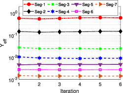
Figure 15. Variation of  for each segment with iteration.
Download figure:
Standard image High-resolution image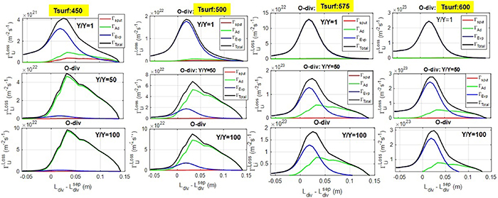
Figure 16. Components of emitted Li fluxes along the outer divertor as a function of peak surface temperature ad-atom to sputtering yield (Y = 0.001, SOLPS main ion particle flux is used). Ad-atom mainly affects the total Li loss processes at lower surface temperature region while evaporation drives the total Li fluxes at the higher temperature region.
Download figure:
Standard image High-resolution image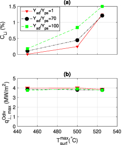
Figure 17. Dependency of ad-atom to sputtering yield uncertainties on the (a) Li concentration at OMP separatrix and (b) peak plasma heat flux ( ) at the outer divertor.
Download figure:
Standard image High-resolution image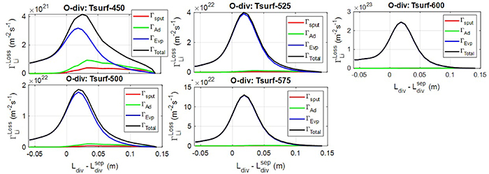
Figure 18. Components of emitted Li fluxes (initial iteration) along the outer divertor as a function of peak surface temperature (Y = 0.001 and Y
 /Y
/Y = 1, SOLPS main ion particle flux is used). For increasing surface temperature, evaporation flux is strongly enhanced due to a strong dependency on the surface temperature.
Download figure:
Standard image High-resolution imageA.3. SOLPS-ITER and MHD code coupling iteration
The LM MHD/heat transfer code computes the thickness of the Li layer, the velocity, and the Li surface temperature, using the surface heat fluxes (figure 5) computed by SOLPS as input data. The calculated LM surface temperature and total emitted Li fluxes from an LM surface based on the corresponding SOLPS heat flux are shown in figure 9. The evaporation flux is strongly increased with increasing the surface temperature, as evaporation rates strongly depend on the surface temperature. The LM thickness was kept constant at 5 mm while the inlet flow velocity was adjusted to achieve different peak T to identify the tolerable T
 . Table 3 shows the MHD simulation parameters, higher flow speed provides lower T
 due to the cooling. Li flow at the inner divertor is shown to be comparatively slower due to lower energy flux, while the outer divertor Li flow is shown to be higher to keep the same LM surface temperature.
Table 3. MHD code simulation parameters showing the relationship between inlet Li flow velocity and T based on the incident heat flux (figure 5).
T
| U (m s−1) (m s−1) | U (m s−1) (m s−1) |
|---|---|---|
| 450 | 7.5 | 1.50 |
| 500 | 3.0 | 0.53 |
| 525 | 2.0 | 0.40 |
| 545 | 1.5 | 0.37 |
| 565 | 1.0 | 0.35 |
| 600 | 0.5 | 0.275 |
Table 4. Li ions and neutrals are returned to the wall and targets depending on the sourcing rate: at lower sourcing rates, mostly Li ions are redeposited on the target, while at higher sourcing rates, Li neutrals are returned to the walls, targets, and pump. Here, the returned percentage is indicated by the ratio ( ).
).
 ( ( ) ) | ||||
|---|---|---|---|---|
T
|
 ( ( s−1) s−1) | φtargets | φwalls |
 ( ( ) ) |
| 450 | 0.271 | 93 | 1 | 5.9 |
| 500 | 0.094 | 83 | 1.5 | 14.9 |
| 525 | 2.32 | 73 | 1.3 | 25.28 |
| 550 | 3.35 | 72 | 1 | 25.7 |
| 565 | 4.71 | 71 | 1 | 27.5 |
| 600 | 13.66 | 51.1 | 0.67 | 47.3 |
The iteration process continued until the solution converged, meaning that the newly computed heat flux based on the emitted Li fluxes is applied as an input to the MHD code, and vice-versa (see figure 25). The emitted Li fluxes reduce plasma heat flux via Li dissipation processes at the higher surface temperature region. Consequently, the 2nd iteration and subsequent iterations provide a slightly lower peak surface temperature compared to the 1st iteration (see figure 11), as T depends on the flow velocity and incident heat flux. Furthermore, the surface temperature (i.e. emitted Li fluxes) becomes saturated in the higher iterations (see figure 26), indicating the convergence of the coupling process. More specifically, the convergence of the coupling processes is confirmed by checking both code outputs for each iteration, and the relative changes are found to be very small as shown in figure 25.
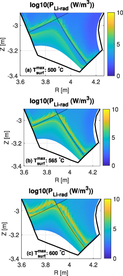
Figure 19. Radiation due to Li dissipation processes in the case of peak surface temperatures of (a) 500 ∘C, (b) 565 ∘C, and (c) 600 ∘C. Li radiation increases with Li sources. Here, Li neutral, line, and bremsstrahlung radiation are considered. Bremsstrahlung radiation is very small, while line radiation is the most dominant. For the highest T case, the total radiation is approximately 14.5 MW, with Li neutral radiation accounting for nearly 4.2 MW and line radiation nearly 10.3 MW. Li primarily radiates in the divertor region below the X-point, as Li is a low Z element (Z = 3) and does not have many charge states. Li3+ is fully stripped and migrates to the core with no further radiation.
Download figure:
Standard image High-resolution image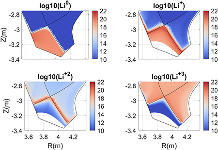
Figure 20. Distribution of Li neutral and ions in the case of the peak surface temperature 565 ∘C. Li neutral is confined near the divertor surfaces while Li3+ is distributed over the whole plasma volume at high sourcing levels, reaching to core ∼5%.
Download figure:
Standard image High-resolution image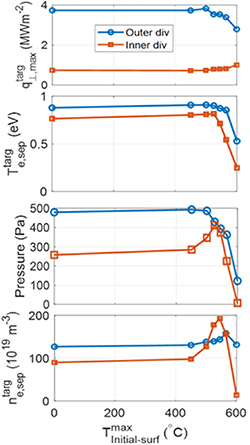
Figure 21. Dependency of (a) peak plasma heat flux, (b) electron temperature at the separatrix, (c) total plasma pressure at the separatrix, and (d) electron density at the separatrix as a function of T .
.
Download figure:
Standard image High-resolution image
Figure 22. Radial profile of electron temperature (Te
) at the outer divertor as a function of T . The combined puffing of D2 (
 ) and Ne (
 ) is used for the Li analysis. Therefore, the impact of these gases has already reduced the Te
to lower than 1 eV at the separatrix. Te
increases in the far SOL.
) is used for the Li analysis. Therefore, the impact of these gases has already reduced the Te
to lower than 1 eV at the separatrix. Te
increases in the far SOL.
Download figure:
Standard image High-resolution image
Figure 23. Poloidal profile of electron temperature across the 3rd flux tube outside of the separatrix. Here, the outer X-point and OMP are highlighted by the dotted black lines. The electron temperature is significantly reduced in the divertor region (i.e. below the X-point) with increasing Li sourcing, indicating the contribution of Li electron cooling via dissipation processes. On the other hand, Te is shown to be almost similar in the upstream region (i.e. OMP), which also indicates lower electron cooling upstream via Li.
Download figure:
Standard image High-resolution image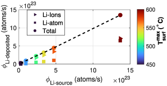
Figure 24. The dependency of Li deposition (i.e. Li sticking) on the target and walls, both as ions and atoms, is examined as a function of Li sourcing rate. Simulation results indicate that among the total Li ions, nearly 99 are redeposited to the target, while the rest is deposited to walls. The presence of neutral atoms is minimal at lower sourcing rates, indicating full ionization of Li and redeposition on the target as ions. However, Li atoms deposited on the walls, pumps, and targets are comparatively higher and almost comparable to Li ions for the highest Li sourcing case. In the highest Li sourcing case, the highest amount of Li atoms is deposited on the targets, followed by the pump and walls.
Download figure:
Standard image High-resolution image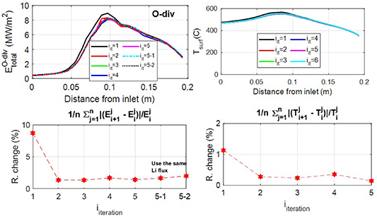
Figure 25. SOLPS-MHD code coupling involves verifying both code outputs. Here, R. change indicates the relative change between two successive steady-state SOLPS run heat flux profiles, and the definition of relative error is mentioned in the figure title. The convergence of the two codes is shown for the peak surface temperature of 565 ∘C. SOLPS shows nearly 1 relative errors (mainly Monte–Carlo noises), as the same Li fluxes are used for the standalone SOLPS run 5–1 and 5–2, which also provide similar relative errors. Regarding the left bottom figure, i
 = 5–1 represents the relative errors between iteration 5 and standalone SOLPS run 5–1, while i
 = 5–2 represents the relative errors between standalone SOLPS run 5–1 and 5–2. Standalone SOLPS runs 5–1 and 5–2 refer to runs without SOLPS-MHD coupling (i.e. using SOLPS only with the same Li fluxes). Specifically, the solution of SOLPS+MHD at iteration 5 is used as input for both 5-1 and 5-2, and then SOLPS is run using the same Li fluxes as in iteration 5 until convergence, to understand the sensitivity of SOLPS. The relative error slightly increases at 5-2 compared to 5-1. It is shown that the SOLPS output can slightly deviate using the same input conditions, which represents the SOLPS internal error mainly due to Monte Carlo noises. Therefore, SOLPS-MHD code coupling shows nearly 2
 error, which is on the order of the MC noise in the SOLPS simulation.
Download figure:
Standard image High-resolution image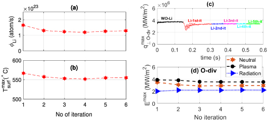
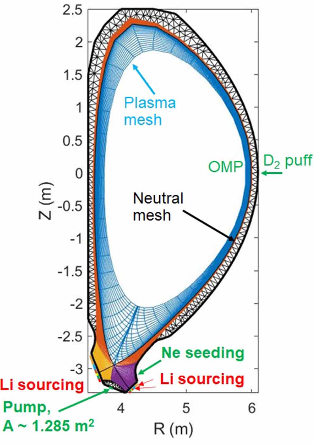
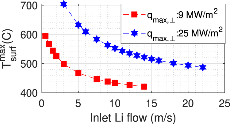
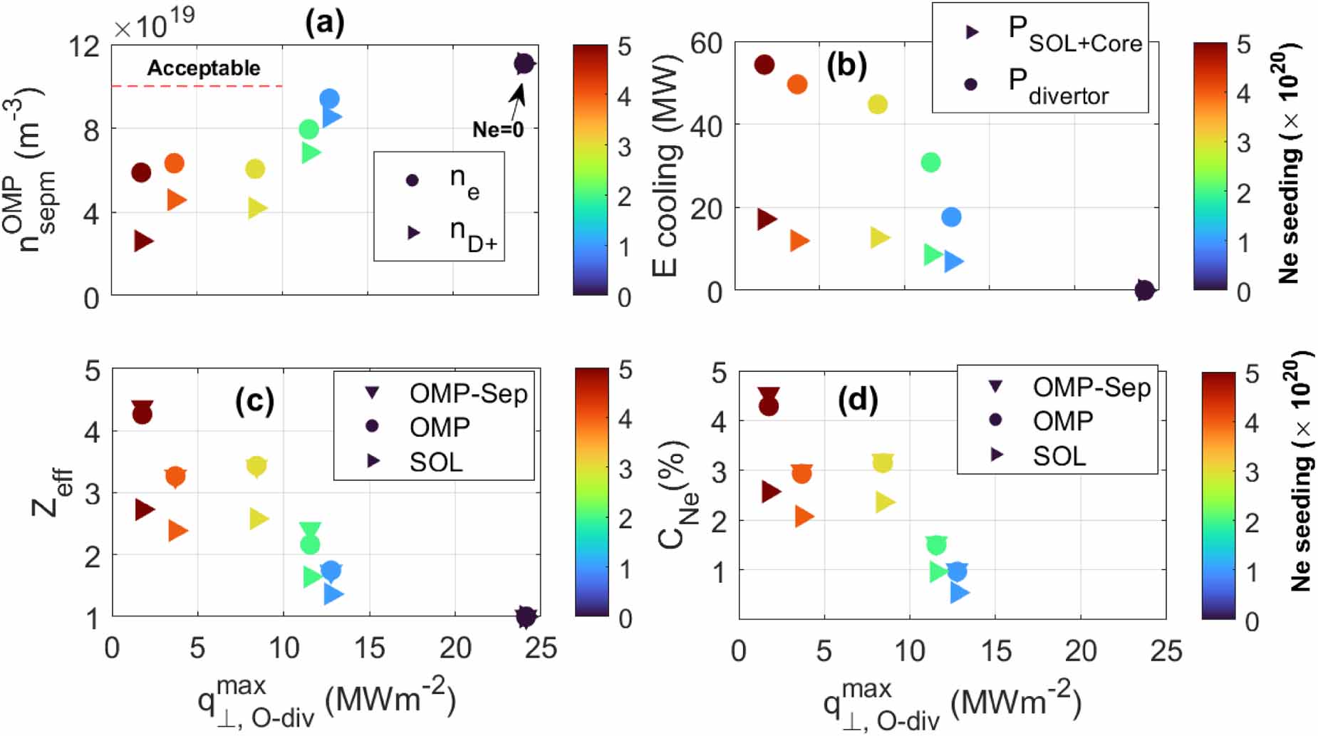
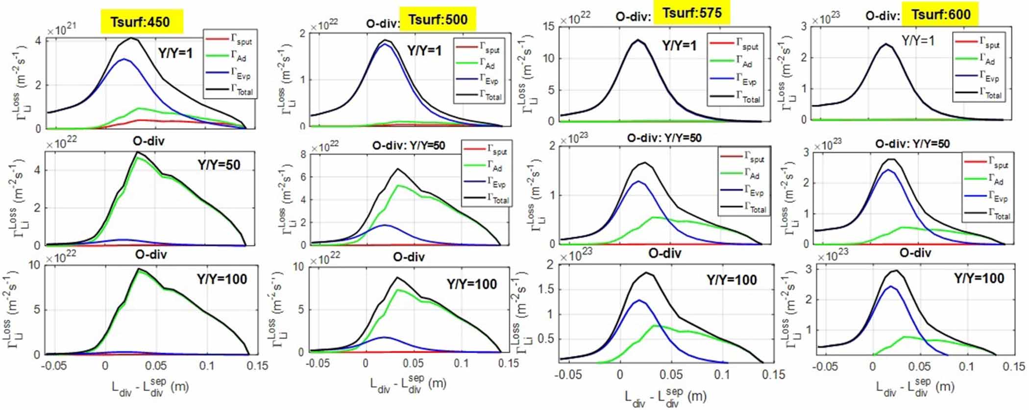
Figure 26. (a) Dependency of total emitted Li fluxes along the outer divertor and (b) peak surface temperature along the outer divertor as a function of iteration, (c) time evolution of peak plasma heat flux ( ) at the outer divertor, and (d) peak energy flux components (
 ) at the outer divertor as a function of iteration. The peak surface temperature, total emitted Li fluxes, and energy flux components become saturated with iteration, which clearly indicates the convergence of the coupling processes. Furthermore, the peak plasma heat flux (also heat flux profile) at the outer divertor is saturated with time, which also indicates the convergence of the coupling processes.
Download figure:
Standard image High-resolution image