


Abstract
According to recent DIII-D experiments (Logan et al 2024 Nucl. Fusion64 014003), injecting edge localized electron cyclotron current drive (ECCD) in the counter-plasma-current (counter-Ip) direction reduces the n = 3 resonant magnetic perturbation (RMP) current threshold for edge-localized mode (ELM) suppression, while co-Ip ECCD during the suppressed ELM phase causes a back transition to ELMing. This paper presents nonlinear two-fluid simulations on the ECCD manipulation of edge magnetic islands induced by RMP using the TM1 code. In the presence of a magnetic island chain at the pedestal-top, co-Ip ECCD is found to decrease the island width and restore the initially degraded pedestal pressure when its radial deposition location is close to the rational surface of the island. With a sufficiently strong co-Ip ECCD current, the RMP-driven magnetic island can be healed, and the pedestal pressure fully recovers to its initial ELMing state. On the contrary, counter-Ip ECCD is found to increase the island width and further reduce the pedestal pressure to levels significantly below the peeling-ballooning-mode limited height, leading to even stationary ELM suppression. These simulations align with the results from DIII-D experiments. However, when multiple magnetic island chains are present at the pedestal-top, the ECCD current experiences substantial broadening, and its effects on the island width and pedestal pressure become negligible. Further simulations reveal that counter-Ip ECCD enhances RMP penetration by lowering the penetration threshold, with the degree of reduction proportional to the amplitude of ECCD current. For the ∼1 MW ECCD in DIII-D, the predicted decrease in the RMP penetration threshold for ELM suppression is approximately 20%, consistent with experimental observations. These simulations indicate that edge-localized ECCD can be used to either facilitate RMP-driven ELM suppression or optimize the confinement degradation.
Export citation and abstract BibTeX RIS

Original content from this work may be used under the terms of the Creative Commons Attribution 4.0 license. Any further distribution of this work must maintain attribution to the author(s) and the title of the work, journal citation and DOI.
1. Introduction
Tokamak discharges operating in high-confinement mode (H-mode) exhibit intermittent bursts of heat and particle transport originating from the outer regions of the plasma, known as type-I edge-localized modes (ELMs) [1]. The periodic and transient power load exerted on the plasma-facing components by these ELMs is a critical concern for the integrity and lifespan of such components in future high-power H-mode devices, including the International Tokamak Experimental Reactor (ITER) [2]. As a result, effective ELM control is of utmost importance for the operation of fusion devices like ITER [2]. Resonant magnetic perturbations (RMPs) have emerged as a promising method for ELM control [3], with complete RMP-driven ELM suppression initially demonstrated on DIII-D [3–6]. Subsequently, ELM mitigation or complete suppression has been successfully demonstrated on JET [7], ASDEX-Upgrade [8], MAST [9], KSTAR [10] and EAST [11].
The successful demonstration of RMP-driven ELM suppression in tokamaks worldwide comes with well-documented constraints on access conditions. These constraints include: (1) the existence of separated narrow q95 windows for full ELM suppression by RMP with n = 1–3 [5, 12–21], (2) a lower bound limit of toroidal rotation [22] and (3) an upper bound limit of pedestal density [15, 22, 23] (with ne,ped/nG < 0.5, here nG is the Greenwald density limit [24]) to access ELM suppression, and (4) the sensitivity of ELM suppression on the triangularity of plasma shape [15, 22, 25, 26]. Addressing the mechanisms behind these constraints of access conditions is crucial in reinforcing the physics basis for predicting reliable and robust ELM suppression in ITER.
Significant progress has been achieved in understanding the physics behind RMP-driven ELM suppression. Extensive validations, comparing experiments and MHD modeling, have revealed the crucial role of the edge multi-mode kink response in amplifying edge magnetic perturbations that favor ELM suppression [27–34]. MHD simulations indicate that RMP induces mode coupling to ballooning modes, contributing to ELM mitigation and suppression [35–37]. Fast nonlinear bifurcation leading to ELM suppression has been observed in both DIII-D [38] and EAST [11], highlighting the significance of nonlinear magnetic island formation [39]. Recent nonlinear two-fluid MHD simulations [40, 41] and analytical theory [42, 43] have demonstrated that the penetration of applied RMP results in RMP-driven ELM suppression and the frequently observed density pump-out. Specifically, RMP-driven magnetic islands at the top and foot of the pedestal are responsible for ELM suppression and density pump-out, respectively, by limiting the growth of the pedestal and enhancing particle transport [40, 41]. The mechanism of magnetic island formation effectively captures the fast-timescale (∼ms) bifurcation in plasma flow and magnetic perturbations during ELM suppression. Furthermore, it agrees with the trends outlined in the foreword, such as the dependence of the RMP threshold, for ELM suppression access, on plasma rotation and density [41], and the existence of separate narrow q95 windows [14, 44]. These consistencies between the two-fluid MHD model and experiments enable the quantitative prediction of ELM suppression in ITER [45] that the required RMP current for ELM suppression is well within its designed capability. However, uncertainties arise due to the anticipated significantly lower plasma rotation and notably higher density in ITER, which may impact its ability to suppress ELMs. Additionally, the applied RMP results in confinement degradation [46], necessitating the optimization of plasma confinement during ELM suppression [47]. Hence, optimizing the approach for achieving robust ELM control is critical.
Recent experiments conducted in DIII-D delved into the use of edge localized electron cyclotron current drive (ECCD) to manipulate RMP-induced ELM suppression [48]. The findings reveal that injecting co-Ip ECCD during RMP-driven ELM suppression leads to a back transition to ELMing, while counter-Ip ECCD reduces the n = 3 RMP current threshold required for complete ELM suppression [48]. This exploration in DIII-D introduces a potential actuator to enhance RMP-driven ELM suppression. The experiment's hypothesis is grounded in well-understood physics concerning the control of neoclassical tearing mode (NTM) using ECCD [49–53]. Specifically, co-Ip ECCD stabilizes the magnetic island by increasing the negative tearing stability Δ' [54, 55] and replacing the missing bootstrap current [56–58]. However, unlike the core NTM, characterized by a large magnetic island spanning approximately 10% (or more) of the minor radius, the RMP-driven magnetic island at the top of the pedestal for ELM suppression is significantly smaller, typically around 1%–2% of the minor radius in width [41, 44]. Additionally, the applied RMP can trigger multiple magnetic island chains at the top of the pedestal [44], which impacts the deposition of ECCD. As a result, it is imperative to theoretically examine the interaction between ECCD and RMP-driven magnetic islands to form a solid basis for extrapolation of this actuator to future machines.
The objective of this paper is to simulate the impact of edge localized ECCD on RMP-driven ELM suppression using two-fluid calculations. The TM1 code [59, 60] is employed in this study to simultaneously stimulate RMP penetration, the associated density and thermal transport, and the manipulation of this process by ECCD. Systematic scans are performed to examine the sensitivity of the stabilizing/destabilizing effect on the RMP-driven magnetic island on the magnitude of the ECCD current, its radial deposition location, and direction. Additionally, the RMP current is varied to explore the dependence of the RMP threshold, required for accessing ELM suppression, on the amplitude of counter-Ip ECCD. Further simulations are conducted to investigate the effect of multiple magnetic island chains on the broadening of ECCD current and its diminishing stabilizing/destabilizing impact. The organization of this paper is as follows: section 2 introduces the TM1 numerical model with ECCD, while section 3.1 provides details about the experimental equilibrium profiles and plasma parameters. Section 3.2 presents the results of nonlinear simulations on the ECCD effect on RMP-driven magnetic islands. The relationship between the RMP penetration threshold and ECCD current is discussed in section 3.3. Finally, section 4 contains the concluding discussion, and a summary of the findings.
2. Numerical model
TM1 code [59–61] is used to simulate the nonlinear resonant field penetration and the associated enhanced parallel collisional transport in the pedestal of DIII-D plasmas. TM1 is a nonlinear two-fluid MHD code based on the large aspect-ratio approximation with circular cross section. TM1 includes the nonlinear coupling of harmonics of each helicity, and it solves the two-fluid MHD equations, including the generalized Ohm's law, the motion equation in the parallel and perpendicular direction, the continuity equation and the thermal transport equation, the details of which are introduced in [41]. To simulate the manipulation of RMP-driven magnetic island by ECCD current, the above MHD equations are still used, but the Ohm's law is modified to

where d/dt = ∂/∂t +
v
⊥·∇, ψ is the perturbed helical flux. Ω = βd1 determining the diamagnetic drift frequency, β = 4ne
Te/B2, d1 = ωce/ve, ωce and ve are the electron cyclotron (EC) and collisional frequency, respectively. j is the toroidal plasma current density, and the bootstrap current density is calculated from jb = −cb
 0.5(cT
ne
Te' + Te
ne')/Bθ
, where cb is a constant of order of unity, cT = 0.367, = r/R, and Bθ
the poloidal magnetic field. jeccd is the non-inductive current density driven by ECCD. It should be noted that the heating effect from EC resonance heating (ECH) is not considered.
0.5(cT
ne
Te' + Te
ne')/Bθ
, where cb is a constant of order of unity, cT = 0.367, = r/R, and Bθ
the poloidal magnetic field. jeccd is the non-inductive current density driven by ECCD. It should be noted that the heating effect from EC resonance heating (ECH) is not considered.
Due to the spatial diffusion of fast electrons, the EC current density depends on both the wave deposition region and the transport of the fast electrons generated by the EC wave. An appropriate model for describing the ECCD current density profile has to include the ECCD current source as well as the parallel and the perpendicular transport of the fast electrons. Following [62] the ECCD current density is described by the following equation
where χ||f and χ⊥f are the parallel and perpendicular fast electron transport coefficients defined in [62], respectively, and υf is the collisional frequency of fast electron. Here jeccd0 is the source current density driven by ECCD,
where jec0, Wdep, and rds specify the magnitude, the radial full 1/e width, and the deposition location of the source, respectively. A schematic diagram of ECW deposition with respect to the magnetic island is shown in figure 1. П (ξ0, Δξ) is a square box function for taking into account the wave deposition profile along the helical angle ξ = mθ + nφ, and ξ0 is the center of ECW along the helical angle. Here, m and n are the poloidal and toroidal mode numbers, respectively. The ECW deposition region is assumed to be centered at ξ = 0, with an instantaneous deposition width Δξ = mΔθ + nΔφ along the helical angle. Consequently, П = 1 for ξ0− Δξ < ξ < ξ0 + Δξ (the gray box in figure 1), and П = 0 elsewhere. The total ECCD source current is obtained by integrating jeccd0 over the plasma cross section. In the following simulations, static magnetic island is driven by static RMP, and its O-point and X-point are at ξ = 0 and ξ = ±π.
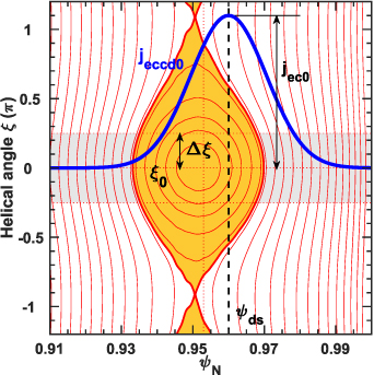
Figure 1. Schematic diagram for the setup of source ECCD current around the edge magnetic island. The blue curve shows the ECCD source current density jeccd0 with peak amplitude jec0, radial deposition location ψds, and the instantaneous wave deposition width 2Δξ centered at ξ0 = 0 along the helical angle in the gray shaded region.
Download figure:
Standard image High-resolution imagePreviously, nonlinear single-fluid simulations using the TM1 code have studied the stabilization of core NTMs via continuous and modulated ECCD in ASDEX-Upgrade and EAST [62–65]. TM1 nonlinear two-fluid simulations have been used successfully to simulate magnetic island formation due to RMP and the modification of pedestal height and width leading to ELM suppression in DIII-D and KSTAR [14, 40, 41, 44, 45].
For clarification, the following quantities denoting different types of current density will be used:
-
 : the m/n = 0/0 component of ECCD source current density jeccd0 calculated from equation (3).
 -
: the m/n = 0/0 component of ECCD driven current density jeccd calculated from equation (2).
- ICD: the ratio of the total ECCD source current to plasma current Ip. Positive (negative) ICD refers to co-Ip (counter-Ip) ECCD injection.
- j0: the equilibrium plasma current density.
-
or : the plasma screening current density of the m/n = 11/3 or 9/3 component caused by RMP.


3. Numerical results
3.1. Input for TM1 simulations
The target of our study is a low-collisionality DIII-D discharge, configured in the ITER-similar-shape as depicted in figure 2(a). The plasma current is set at Ip = 1.7 MA, with a toroidal field of Bt = 2.1 T, and major and minor radius R/a = 1.7 m/0.6 m. The edge safety factor is q95 = 3.45, while the neutral bean injected power and torque are approximately 7.5 MW and 7.3 Nm, respectively. Other parameters include βN ≈ 2, Zeff ≈ 2, normalized electron pedestal collisionality v* e ≈ 0.1–0.2. In the experiment, the in-vessel coils (I-coils) are configured to generate n = 3 RMPs, where n is the toroidal mode number. Additionally, we utilized 1–3 MW edge localized ECH for injecting either co-Ip, counter-Ip ECCD or heating at the top of the pedestal. Figure 2(a) illustrates the trace and deposition of the ECH, targeting at the q = 11/3 rational surface based on TORAY [66] calculations, and the grey line indicates the injection location of ECCD from the low field side.

Figure 2. Equilibrium and profiles of target plasma 169964 in terms of (a) poloidal cross-sections of plasma shapes, profiles of (b) safety factor q, electron density and temperature, (c) plasma current density j0, ECCD driven source current density in co-Ip for shot 169964, ECH for 169966 and counter-Ip for shot 169967, and (d) E × B rotation frequency. Here, the I-coils (IL, IU), the m/n = 11/3 magnetic island (magenta) and the ECH trace and deposition (red) are shown in (a).
Download figure:
Standard image High-resolution imageIn this paper, the analysis relies on the equilibrium and profiles (q, ne, Te, E × B rotation ωE = Er/|RBθ |, plasma current density) obtained from shot 169964 at 2.1 s, as depicted in figures 2(b)–(d). At this specific time, the density pump-out had already occurred after the n = 3 RMP with 4 kA coil current was activated at 2 s, while the plasma was still experiencing ELMs. The comprehensive time evolution of that shot is further described in [48]. Based on previous TM1 simulations [40, 41], it has been established that magnetic island formation at the pedestal-foot is responsible for density pump-out, while magnetic island formation at the pedestal-top leads to ELM suppression. Consequently, using the equilibrium and profiles after density pump-out simplifies the TM1 simulations to focus on ELM suppression caused by pedestal-top magnetic island formation. Therefore, the simulations to follow will primarily concentrate on m/n = 11/3 RMP penetration at the pedestal-top, with its rational surface located at ψN = 0.953. Other components resonating at the pedestal-foot are not included for the purpose of accelerating the simulations unless mentioned elsewhere. The profiles for ECCD source current density, calculated by TORAY code [66], are illustrated in figure 2(c). Specifically, for shot 169964, the 1.6 MW co-Ip ECH drives 5.2 kA ECCD source current with ICD = 0.306% and a radial full 1/e width of Wdep = 0.015ψN, resulting in back transition to ELMing. On the other hand, for shot 169967, the 1 MW counter-Ip ECH drives −8 kA ECCD source current with ICD = −0.47% and Wdep = 0.02ψN, effectively sustaining stationary ELM suppression.
The cylindrical geometry utilized in the TM1 model is substantially different from the toroidal strongly shaped geometry in the DIII-D experiment. To account for this distinction, we incorporated the fully toroidal MHD code GPEC [67] to calculate the perturbed 3D magnetic equilibrium, which serves as the magnetic boundary condition for TM1 simulations. Leveraging the kinetic equilibrium, as depicted in figure 2, GPEC perturbatively computes the total (vacuum plus ideal MHD kink response) 3D magnetic response of the plasma to the I-coils in full toroidal strongly shaped geometry, with a specific toroidal mode number, in this case, n = 3. The calculated harmonics of the n = 3 RMP (m/n = 11/3 in this context) that resonate with the edge rational surfaces are subsequently employed as the boundary condition for the TM1 simulations at ψN = 1.
Additional parameters, including the particle diffusivity, electron thermal diffusivity, neoclassical resistivity and electron collisionality are obtained from TRANSP [68] power and particle balance calculations by using the kinetic equilibrium and profiles as shown in figure 2. The initial conditions for TM1 simulations consist of Br 11/3 = 7.6 Gauss, representing 4 kA RMP current at the plasma edge from GPEC. The neoclassical resistivity is approximately 1 × 10⁻⁷ Ωm at the pedestal top, while the perpendicular transport coefficients μ ∼ χ⊥ ∼ 3D⊥ = 0.5 m2 s−1 around the pedestal-top. Here, μ, χ⊥ and D⊥ are the viscosity, thermal and particle diffusivity, respectively. These parameters lead to magnetic Reynold number S ∼ 1.1 × 10⁸, χ||/χ⊥ = 2.5 × 10⁸, and χ||f/χ⊥f = 5 × 10⁹.
3.2. ECCD effect on pedestal-top magnetic island
In the simulations, only the 11/3 component and its harmonics (22/6, 33/9, ...) are included, unless stated otherwise. According to TM1 simulations, the threshold RMP current required to trigger the 11/3 magnetic island is 3.15 kA. The simulations follow a similar approach to the experiment, where the n = 3 RMP current is rapidly ramped up from 0 to 4 kA in 20 ms to explore magnetic island formation at the top of the pedestal. Once the island reaches saturation, the ECCD driven current with varying amplitudes is activated at t = 0.45 s, with a deposition location ψds = 0.955 and a 1/e width of Wdep = 0.015ψN, similar to shot 169964. Additionally, ξ0 = 0 and Δξ = 0.25 π are used unless otherwise specified.
Figure 3 illustrates a typical simulation with the time evolution of the n = 3 RMP coil current, normalized 11/3 magnetic island width, and the pedestal electron pressure while scanning the total ECCD source current ICD from −0.9% to 0.9% of the plasma current. The 4 kA RMP promptly triggers the 11/3 magnetic island penetration at the pedestal-top, with the saturated island width approximately ∼0.021ψN, as shown in figure 3(b). Concurrently, the pedestal pressure is decreased from 3.65 kPa to 2.6 kPa due to enhanced parallel collisional transport across the island, as shown in figure 3(c). According to [41, 44], the pedestal pressure has to be decreased to 3 kPa (a 15% reduction) by the pedestal-top magnetic island to achieve ELM suppression in discharge 169964. The magnitude of reduction in the pedestal pressure depicted in figure 3(c) exceeds 15%, which is taken to be the access to complete ELM suppression. Upon turning on the ECCD current at 0.45 s, co-Ip ECCD stabilizes the 11/3 magnetic island, leading to a decreased island width, while counter-Ip ECCD destabilizes the 11/3 magnetic island. For counter-Ip ECCD, increasing ICD from 0 to −0.9% results in the normalized 11/3 island width increasing from 2.1% to 3.2% of the minor radius, and the pedestal pressure decreasing from 2.6 kPa to 2.1 kPa. On the other hand, for co-Ip ECCD, increasing ICD from 0 to 0.55% decreases the normalized 11/3 island width from 2.1% to 1.2% of the minor radius and restores the pedestal pressure from 2.6 kPa to 3.2 kPa. The recovery of the pedestal pressure causes its height to surpass the 3 kPa threshold, taken to be the loss of ELM suppression. When the co-Ip ECCD current exceeds 0.55%, it leads to full stabilization of the 11/3 island, as evident from the rapid reduction of the island width to ∼0.5% during the shielding state and a quick rise in the pedestal pressure.

Figure 3. TM1 simulations of the influence of ECCD on edge magnetic island driven by n = 3 RMP in terms of time evolution of (a) n = 3 RMP coil current, (b) m/n = 11/3 magnetic island width, and (c) the pedestal electron pressure at different amplitude of normalized ECCD source current ICD. Here, ψds = 0.955, Wdep = 0.015ψN, which are similar to that of shot 169964.
Download figure:
Standard image High-resolution imageAs illustrated in figure 3, the 11/3 magnetic island induces enhanced parallel electron transport, resulting in profile flattening and a reduction in the pedestal pressure [41]. For ECW driven fast electrons, their parallel transport is more than one order higher compared to thermal electrons, leading to an even stronger broadening effect by the 11/3 magnetic island. As depicted in figure 4, the 0/0 component of the ECCD current density experiences broadening, and the total driven current amplitude is decreased by both the parallel and perpendicular transport of fast electron in the presence of the 11/3 magnetic island. Specifically, for co-Ip ECCD with ICD = 0.3%, the 11/3 magnetic island becomes smaller, but it broadens the distribution of the 0/0 component of jeccd, with the peak current density decreased by ∼40% and the total driven current decreased to ∼0.26%. On the other hand, for counter-Ip ECCD with ICD = −0.3%, the increased 11/3 magnetic island width leads to a 46% decrease in the peak current density of the 0/0 component of jeccd, and the total driven current is −0.24%. The 2D profile of ECCD current density jeccd, including m/n = 0/0, 11/3 and harmonic components, localizes and maximizes at the O-point of the magnetic island for both co-Ip and counter-Ip ECCD.

Figure 4. TM1 simulations show broadening of ECCD current density for (a), (b) co-Ip ECCD with ICD = 0.3% and (c), (d) counter-Ip ECCD with ICD = −0.3%. In (a) and (c), radial profiles of the 0/0 component of the ECCD source current density  (black) and the driven current density
  (red or blue) are shown. The 2D ECCD current density jeccd contours in (b) and (d) includes m/n = 0/0, 11/3 and harmonic components driven current density.
Download figure:
Standard image High-resolution imageA full scan of the total ECCD source current ICD and radial deposition location ψds is conducted to examine their impact on the magnetic island width and the pedestal height, as presented in figure 5. The 2D contour plots show the variation of the 11/3 magnetic island width and the pedestal pressure versus ψds and ICD for Wdep = 0.75%, 1.5% and 3% of the minor radius. The ECCD is activated at 0.45 s after the saturation of the 11/3 magnetic island. For Wdep = 0.0075ψN and 0.94 < ψds < 0.965 (figures 5(a) and (b)), increasing the co-Ip ECCD current density leads to smaller magnetic island and recovery of the pedestal pressure, whereas the opposite is observed for the counter-Ip ECCD current density, consistent with the tendencies shown in figure 3. A specific region of ECCD deposition around the 11/3 magnetic island region leads to back-transitions from ELM suppression to ELMing, indicated by the black curve in figure 5(b), with a minimum ICD of 0.45%. Radially depositing the ECCD away from the magnetic island region has minimal impact on both the island width and pedestal pressure. When the radial distribution of ECCD current density is broadened by increasing Wdep to 0.015ψN and 0.03ψN, it leads to a weaker stabilizing/destabilizing effect on the 11/3 magnetic island and a less pronounced influence on the pedestal pressure, as shown in figures 5(c)–(f). Additionally, the minimum ECCD source current required to cause back-transition from ELM suppression to ELMing increases to ICD = 0.55% for Wdep = 0.015ψN and ICD = 0.77% for Wdep = 0.03ψN. This behavior is expected since, for the same total ECCD source current ICD, the ECCD source current density jeccd0 decreases for larger Wdep, resulting in weaker stabilizing/destabilizing effect. Shots 169964 with co-Ip ECCD and 169967 with counter-Ip ECCD are shown in figures 5(c) and (d) for comparison, indicating sustained ELM suppression for both shots. However, the co-Ip ECCD leads the pedestal height close to the transition boundary to ELMing for shot 169964. In the experiment, co-Ip ECCD in shot 169964 led to back transition to ELMing, and ELM suppression was sustained with counter-Ip ECCD in shot 169967. The predicted tendencies in figure 5 are qualitatively consistent with experimental observations. Nevertheless, different to the simulations, back-transition to ELMing occurs in the experiment for shot 169964, suggesting a possible change in the pedestal stability [48] caused by the edge-localized ECCD current and heating effect, which is not considered in the TM1 simulations.
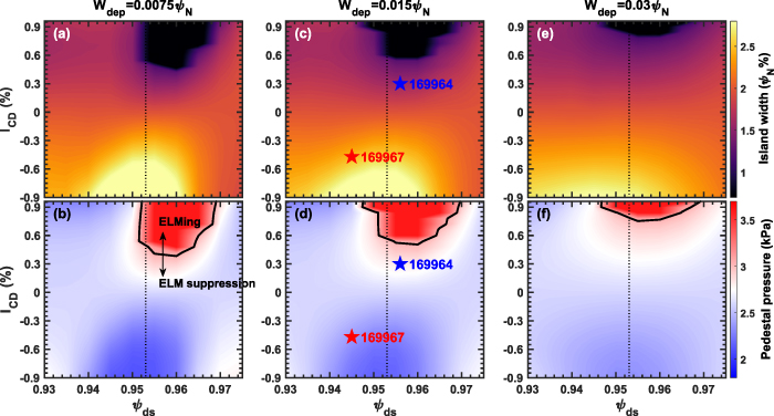
Figure 5. 2D contour plot of the simulated 11/3 magnetic island width and pedestal pressure versus ψds and ICD for (a) and (b) Wdep = ψN0.75%, (c) and (d) Wdep = ψN1.5%, and (e) and (f) Wdep = ψN3%. The experimental cases 169964 and 169967 are shown in (c) and (d) respectively, and the black curves in (b), (d) and (f) indicate the boundary between ELM suppression and ELMing.
Download figure:
Standard image High-resolution imageThe center of the ECCD source current density along the helical angle is systematically scanned to investigate its stabilizing/destabilizing effect when moving the deposition from O-point to X-point of the 11/3 magnetic island. The results are presented in figure 6 as a 2D contour plot of the 11/3 magnetic island width and the pedestal pressure. The ECCD is turned on at 0.45 s after the saturation of the 11/3 magnetic island, with Wdep = 0.015ψN, ψds = 0.955, Δξ = 0.25 π, and ξ0 is scanned from −π (X-point) to 0 (O-point), and then to π (X-point). It shows that, for co-Ip ECCD, its stabilizing effect modestly increases when moving the deposition location from the X-point to the O-point of the 11/3 magnetic island. This is evident from the reduction in magnetic island width and the increase in pedestal pressure. In addition, the strongest effect appears when ξ0 = 0.1 π, due to the existence of small phase difference between RMP and magnetic island even though penetration happens [41, 69]. Interestingly, even when the co-Ip ECCD is deposited at the X-point of the 11/3 magnetic island, it still exhibits a stabilizing effect, albeit weaker. Notably, it is well known that co-Ip ECCD destabilizes the core magnetic island when it deposits at the X-point [54, 55]. Nevertheless, the results shown in figure 6 are reasonable due to following reasons: (1) the ECCD current along the helical angle (or poloidally) is not highly localized at the X-point compared to the poloidal wavelength of the 11/3 magnetic island (figure 2(a)), which is different to the large mode wavelength for core NTM; (2) the enhanced parallel transport of the fast electron broadens the distribution of ECCD current density along the helical angle; and (3) the radial width of ECCD current is comparable to the width of the magnetic island. These factors collectively contribute to the stabilizing effect of co-Ip ECCD, even when deposited at the X-point of the magnetic island.
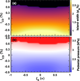
Figure 6. 2D contour plot of the simulated (a) 11/3 magnetic island width and (b) pedestal pressure by scanning ICD and the center of the ECCD along the helical angle ξ0. Here, Wdep = 0.015ψN, ψds = 0.955, Δξ = 0.25 π are used, and the O-point and X-point are at ξ0 = 0 and ξ0 = −π (or π), respectively.
Download figure:
Standard image High-resolution imageThe instantaneous deposition width Δξ is scanned to investigate the sensitivity of the stabilizing/destabilizing effect on the width of ECCD current along the helical angle, as illustrated in figure 7. In these simulations, Wdep = 0.015ψN, ψds = 0.955, and ξ0 = 0 are used. The results reveal that the stabilizing effect of co-Ip ECCD (and the destabilizing effect of counter-Ip ECCD) diminishes as Δξ increases from 0.04 π to 0.2 π, as evidenced by the rising threshold of ICD required to achieve the full stabilization (or destabilization) of the 11/3 magnetic island. However, beyond Δξ > 0.2 π, the stabilizing/destabilizing effect shows no sensitivity on Δξ, indicating that the usage of Δξ = 0.25 π in the TM1 simulations results in the least overestimate of the stabilizing/destabilizing effect by ECCD current.
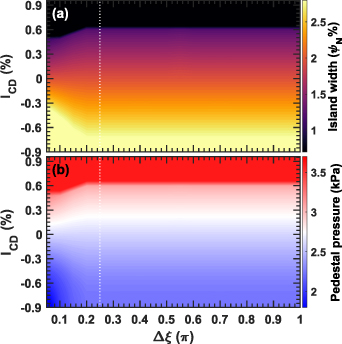
Figure 7. 2D contour plot of the simulated (a) 11/3 magnetic island width and (b) pedestal pressure by scanning ICD and the wave deposition width Δξ along the helical angle.
Download figure:
Standard image High-resolution imageAdditional TM1 simulations by including both the 10/3 and 11/3 resonant components at the pedestal-top reveal that n = 3 RMP with 4 kA coil current is inadequate to trigger both the 10/3 and 11/3 magnetic island chains at the top of the pedestal. Previous comparison between TM1 simulations and DIII-D experiments have shown that a sufficiently strong RMP can induce multiple magnetic island chains at the pedestal-top, expanding the q95 windows for ELM suppression [14, 44]. However, multiple island chains led to strong reduction in the pedestal height and confinement. A critical question is whether ECCD remains effective in manipulating the magnetic island width and the pedestal height when multiple magnetic island chains are present. To address this question, 5 kA RMP current is applied in the simulations and both the 10/3 and 11/3 resonant components are included. Subsequently, the ECCD current amplitude ICD and its radial deposition location are scanned in TM1 simulations, as depicted in figure 8. For these simulations, Wdep = 0.015ψN, ξ0 = 0 and Δξ = 0.25 π are used. Before the ECCD activation, the overlapping 11/3 and 10/3 magnetic islands have saturated widths of 2.9% and 3.3% of the minor radius, respectively, while the pedestal pressure is decreased to 1.8 kPa. When the ECCD is turned on and scanned from ICD = 0.9% in co-Ip direction to ICD = −0.9% in counter-Ip direction, minimal effect is observed on both the magnetic island width and pedestal pressure. Specifically, the 11/3 and 10/3 magnetic island widths vary slightly from 2.6% to 3.3%, and 3.2% to 3.4% of the minor radius, respectively, while the pedestal pressure remains stable at approximately 1.8 kPa. Furthermore, the results show that the radial deposition location of ECCD, ranging from ψds = 0.975 (outside of the 11/3 island) to 0.92 (inside the 10/3 island), has negligible influence on both the island width and pedestal pressure.
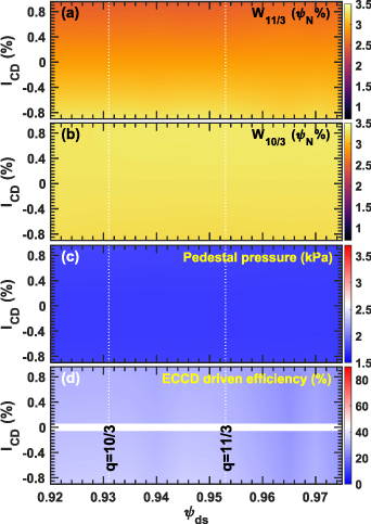
Figure 8. 2D contour plot of the TM1 simulated (a) 11/3 magnetic island width, (b) 10/3 magnetic island width, (c) the pedestal pressure, and (d) the ECCD driven efficiency versus normalized pedestal density pump versus ψds and ICD. Here, 5 kA RMP current is applied to trigger both 11/3 and 10/3 island chains at the pedestal-top, and Wdep = 0.015ψN, ξ0 = 0 and Δξ = 0.25 π are used. The locations of q = 10/3 and 11/3 rational surfaces are shown in white dotted lines.
Download figure:
Standard image High-resolution imageThe presence of overlapping multiple magnetic islands is found to substantially broaden the ECCD current density and reduce its effectiveness. Figure 9 displays the profiles of ECCD current density jeccd0 and jeccd, along with the Poincaré plot of the poloidal magnetic flux surface, in the presence of the 11/3 and 10/3 magnetic islands for Wdep = 0.015ψN, ψds = 0.935, 0.95, and 0.965, with ICD = 0.3%. It is evident that the current density jeccd is significantly broadened compared to the source ECCD current density jeccd0, with the maximum current density reduced from 65 kA m−2 to 15 kA m−2. Moreover, regardless of the location of ECCD current deposition within the overlapping islands region, the driven ECCD current density remains consistently broadened, accounting for the minimal sensitivity of the island width to ψds, as shown in figure 8. Furthermore, the current driven efficiency is substantially decreased, comprising only ∼30%–35% of the source current ICD, as demonstrated in figure 8(d). These outcomes depicted in figures 8 and 9 indicate that edge localized ECCD can be effective in manipulating RMP-driven ELM suppression when the RMP triggers a single magnetic chain at the top of the pedestal. However, in the presence of overlapping magnetic islands, the effectiveness of ECCD is significantly reduced. And in turn, the observations in DIII-D indicate that the 4 kA RMP likely triggered single magnetic island chains around the top of the pedestal.

Figure 9. Multiple magnetic island chains at the pedestal-top broadens the 0/0 component of ECCD current density as shown in (a) for the profile of  (dash curves) and
  (solid curves) at different deposition locations, and (b) Poincare plots of the poloidal magnetic surfaces with 10/3 and 11/3 magnetic island when applying 5 kA RMP current. The profile of ECCD source current density is shown in dashed curves in (a).
Download figure:
Standard image High-resolution image3.3. Counter-Ip ECCD facilitates RMP-driven ELM suppression
According to [48], counter-Ip ECCD has been observed to lower the threshold of RMP current required for ELM suppression. This section presents TM1 simulations aimed at predicting the sensitivity of the threshold of RMP current, necessary to trigger the 11/3 magnetic island, with respect to the amplitude of the counter-Ip ECCD current.
Figure 10 shows examples on how counter-Ip ECCD facilitates RMP penetration, in terms of the time evolution of the 11/3 magnetic island. The parameters used are ψds = 0.955, Wdep = 0.015ψN, ξ0 = 0 and Δξ = 0.25 π. Without ECCD, the threshold RMP current to trigger the 11/3 magnetic island is 3.15 kA. In the case of constant RMP current with IRMP = 2.6 kA, as shown in figure 10(a), it is shielded by the plasma to produce a small magnetic island with W11/3 = 0.0056ψN. Turning on counter-Ip ECCD at 0.45 s leads to RMP penetration and formation of 11/3 magnetic island when ICD < −0.5%. On the other hand, RMP with current lower than 3.1 kA is shielded by the plasma as shown in figure 10(b). Turning on counter-Ip ECCD with ICD = −0.45% at 0.45 s leads to RMP penetration and formation of 11/3 magnetic island when IRMP > 2.7 kA. Typically, counter-Ip ECCD leads to faster penetration for higher RMP currents.

Figure 10. Counter-Ip ECCD facilitates n = 3 RMP penetration in terms of TM1 simulated 11/3 magnetic island width for (a) IRMP = 2.6 kA with different ICD, and (b) ICD = −0.45% with different RMP current.
Download figure:
Standard image High-resolution imageFigure 11 presents the comparison of the profiles of the 0/0 component ECCD source current density  (black curves) and driven current density
  (red curves), and the real (blue curves) and imaginary (dash magenta curves) part of the m/n = 11/3 component plasma screening current density
  induced by RMP (or plasma current density perturbation associated with RMP-driven 11/3 magnetic island) at 0.8 s. Specifically, figures 11(a) and (b) display the current density profiles from the case with IRMP = 2.6 kA and ICD = −0.45% in figure 10(a) at 0.8 s, and the case with IRMP = 2.7 kA and ICD = −0.45% in figure 10(b) at 0.8 s, respectively. Figure 11(a) shows that the co-Ip direction screening plasma current density induced by RMP is more localized at the 11/3 rational surface, with its maximum current density approximately twice that of the maximum ECCD current density. Additionally, the ECCD driven current density is slightly broadened due to the presence of magnetic perturbation, despite the RMP being shielded. When the 11/3 magnetic island forms, it leads to a reversal of the 11/3 component current density at the rational surface, and its maximum amplitude remains about two times that of the ECCD current density. According to TM1 simulations with counter-Ip ECCD, the 0/0 component of the driven current density reduces the total plasma current density around the 11/3 rational surface, thereby affecting both the local current density gradient and tearing stability index Δ'. On the other hand, the 11/3 component ECCD current density (peak magnitude is 1/6 of the 0/0 component, not shown here) compensates for the screening current produced by RMP, facilitating magnetic reconnection. These combined effects enable counter-Ip ECCD to effectively promote RMP penetration.
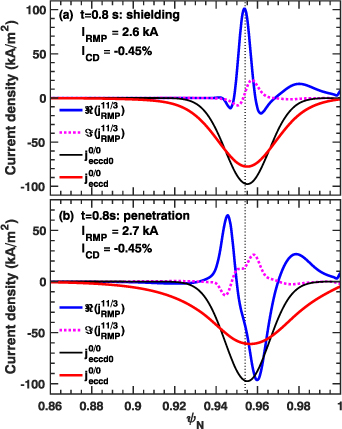
Figure 11. Comparison of the profiles of the 0/0 component of ECCD source current density  (black curves) and driven current density
  (red curves), and the real (blue curves) and imaginary (dash magenta curves) part of 11/3 component screening plasma current density
  induced by RMP at 0.8 s for (a) IRMP = 2.6 kA and ICD = −0.45% and (b) IRMP = 2.7 kA and ICD = −0.45%.
Download figure:
Standard image High-resolution imageA comprehensive scan is conducted, varying both the counter-Ip ECCD source current and the RMP current, to predict the relationship between the RMP penetration current and ICD. This prediction is illustrated in figure 12, which presents a 2D contour plot of the 11/3 ξ0 magnetic island width and the pedestal pressure with respect to IRMP and ICD. Here, ψds = 0.955, Wdep = 0.015ψN, ξ0 = 0 and Δξ = 0.25 π are used. For ICD = 0, it requires 3.15 kA RMP current to trigger the 11/3 magnetic island. As the counter-Ip ECCD current increases, there is an almost linear decrease in the RMP penetration threshold current. For ICD = −0.45%, the RMP penetration threshold is 2.7 kA, which represents approximately a 15% reduction. Doubling the ECCD current to ICD = −0.9% further decreases the RMP penetration threshold current to 2.3 kA, resulting in a ∼27% reduction. For comparison, the threshold RMP current to access ELM suppression for shots 169958 without ECCD and 169981 with 1 MW counter-Ip ECCD are shown in figure 12. Overall, the simulation results are consistent with experimental observations, although the observed threshold RMP current for ELM suppression is ∼0.1–0.15 kA lower than the simulations.
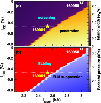
Figure 12. Dependence of RMP penetration threshold on counter-Ip ECCD source current in terms of 2D contour plot of (a) 11/3 magnetic island width, and (b) pedestal pressure versus RMP current and ICD.
Download figure:
Standard image High-resolution imageIn the experiment, the standard H-mode pedestal with RMP-driven ELM suppression in shot 169981 transits from the ballooning boundary to the peeling boundary and enters the super-H channel when an additional 1 MW ECCD is applied [48], indicating the change of the pedestal stability caused by the injection of ECCD current. It is anticipated that edge ECCD might reduce the pedestal collisionality, which helps to increase the bootstrap current and trigger ELMs. Meanwhile, more counter-Ip ECCD destabilizes the magnetic island to larger width and leads to more reduction in pedestal pressure to sustain ELM suppression. In the DIII-D experiment, edge ECCD is found to reduce the pedestal collisionality and broaden the pedestal width, leading to slightly reduced edge bootstrap current and sustaining RMP-driven ELM suppression [48].
Additional TM1 simulations show that facilitating RMP penetration by using counter-Ip ECCD is insensitive to its radial deposition location ψds. Especially, counter-Ip ECCD with deposition inside the 11/3 rational surface for ψds = 0.93–0.95 leads to almost the same reduction in the RMP penetration threshold. This outcome is reasonable since the counter-Ip ECCD inside the 11/3 rational surface still decreases the radial gradient of plasma current density at the 11/3 surface. These findings indicate that counter-Ip ECCD holds promise as a potential actuator to facilitate RMP-driven ELM suppression if it can be injected in the edge pedestal region.
4. Discussion and summary
The simulation results presented in this study demonstrate qualitative consistency with the DIII-D experiment regarding the manipulation of RMP-driven ELM suppression using ECCD. It is important to acknowledge that certain factors have not been accounted for in this analysis, including (a) multiple components resonating at the pedestal region, especially those components caused density pump-out at the pedestal-foot; (b) heating effect even when in ECCD launch orientation; and (c) effect of edge localized current from ECCD on the pedestal stability boundaries between ballooning, peeling-ballooning, and peeling limited. The multiple components are expected to produce stronger radial transport of the fast electron, resulting in broader ECCD current density distribution and lower current driven efficiency. The effects of heating and localized ECCD current in the pedestal-top are expected to shift the pedestal stability toward the peeling limited boundary. These aforementioned missing effects could potentially contribute to the observed transition from a standard H-mode pedestal to a super-H mode pedestal [48, 70] with ELM suppression. Nevertheless, the stabilizing/destabilizing effect of ECCD, as well as the bifurcation towards a super-H pedestal, exhibit favorable characteristics for achieving robust ELM suppression. These findings indicate the potential for synergistically combining ECCD and RMP techniques to effectively control ELM in ITER plasma conditions.
Considering the potential utilization of edge localized ECCD for manipulating RMP-driven ELM suppression in ITER, some may question its relevance. Previous predictions using the same suite of codes have indicated the optimal 3D configuration for ELM control and identified the q95 windows necessary to achieve ELM suppression for ITER standard operation scenario with Ip = 15 MA and Q = 10 [45]. These predictions revealed that the required n = 3 RMP current for ELM suppression is below 40–50 kAt. In this context, we provide a concise estimation of the ECW power needed to facilitate RMP-driven ELM suppression in ITER. For q95 ∼ 3.15, m/n = 9/3 RMP is the key component to suppress ELM. Figure 13 displays the TM1 simulated 9/3 component of the screening plasma current density induced by a 30 kAt n = 3 RMP current with q95 ∼ 3.15 [45], with its maximum reaching approximately 62% of the local plasma current density. Assuming the ECW system designed for ITER drives the same ECCD current with the same radial width as the one used in DIII-D, the 1/e width will be approximately 0.005ψN by considering the different minor radius of ITER and DIII-D. It is estimated that around 9 MW of ECW power would be required to drive a 75 kA (ICD ∼ −0.5%) counter-Ip ECCD current, which is comparable to the screening current depicted in figure 13. Considering the anticipated low plasma rotation and high-density plasma operation in ITER, achieving RMP-driven ELM suppression may necessitate an increased ECCD-driven current and, consequently, a higher ECW power input. Fortunately, the effectiveness of the current drive is also expected to be enhanced owing to the significantly higher electron temperature at the top of the ITER pedestal. One concern we have is that the recently designed ECH antennas cannot deposit ECW at the edge in ITER. In addition, it could be dangerous if the ECW is deposited on the edge plasma, which may damage the device although we ran it safely in the DIII-D experiment. Another concern that may have arisen is the potential requirement for a substantial amount of ECW power to drive counter-Ip ECCD current for ELM control, thereby leaving less ECW power available for core current drive and NTM/sawtooth control. However, thanks to the hysteresis effect in RMP-driven ELM suppression, it is possible to partially or completely eliminate the need for edge localized ECCD current once ELM suppression has been successfully achieved. Nevertheless, more studies from different devices are still required to figure out the operational risks and capabilities of using ECCD to manipulate RMP ELM control.

Figure 13. Comparison of the profiles of plasma current density j0, real part of TM1 simulated 9/3 component of the screening plasma current density  caused by n = 3 RMP, and the 0/0 component of the ECCD source current density
  driven by 9 MW ECW for ITER standard baseline scenario with Ip = 15 MA and Q = 10.
Download figure:
Standard image High-resolution image
Based on our simulations, it appears that edge localized ECCD can be employed in a flexible manner to maintain stable RMP-driven ELM suppression while minimizing the associated confinement degradation, regardless of RMP with different toroidal mode number (i.e. n = 1, 2, 3 and 4). Specifically, counter-Ip ECCD should be utilized to facilitate access to RMP-driven ELM suppression. Once ELM suppression has been successfully achieved, if the confinement degradation resulting from RMP becomes undesirable or there is a need to optimize plasma confinement, co-Ip ECCD can be activated to partially stabilize the magnetic island and restore plasma confinement.
In conclusion, this paper presents nonlinear two-fluid simulations investigating the manipulation of edge magnetic islands induced by RMP using ECCD, aiming to provide insights into DIII-D experiments [48] and RMP ELM control in ITER. Our findings demonstrate that in the presence of a magnetic island chain at the pedestal-top, co-Ip ECCD effectively reduces the island width and restores the initially degraded pedestal pressure, particularly when the ECCD is radially deposited close to the rational surface of the island. By applying a sufficiently strong co-Ip ECCD current, the RMP-driven magnetic island can be healed, and the pedestal pressure can fully recover to its initial ELMing state. Conversely, counter-Ip ECCD is observed to increase the island width and significantly decrease the pedestal pressure, even below the peeling-ballooning-mode limited height, resulting in stationary ELM suppression. These simulation results align with the observations from DIII-D experiments. However, when multiple magnetic island chains are present at the pedestal-top, the ECCD current density experiences significant broadening, and its impact on the island width and pedestal pressure becomes negligible. Further simulations indicate that counter-Ip ECCD enhances RMP penetration by lowering the penetration threshold, and the degree of reduction is proportional to the amplitude of the ECCD current. Considering the 1 MW ECCD in DIII-D, the simulations predict a 20% decrease in the RMP penetration threshold for ELM suppression, consistent with experimental observations.
Acknowledgments
The author Q. Hu is grateful to C. Paz-Soldan and M.E. Fenstermacher for reviewing the manuscript and providing valuable comments to improve it. This material is based upon work supported by the U.S. Department of Energy, Office of Science, Office of Fusion Energy Sciences, using the DIII-D National Fusion Facility, a DOE Office of Science user facility, under Awards Nos. DE-AC02-09CH11466, DE-FC02-04ER54698, DE-SC0022270 and DE-AC52-07NA27344. Q. Yu is partially supported by the Eurofusion Enabling Research Project (CfP-FSD-AWP24-ENR). His work has been carried out within the framework of the EUROfusion Consortium, funded by the European Union via the Euratom Research and Training Programme (Grant Agreement No 101052200—EUROfusion). Views and opinions expressed are however those of the author(s) only and do not necessarily reflect those of the European Union or the European Commission. Neither the European Union nor the European Commission can be held responsible for them.
Disclaimer
This report was prepared as an account of work sponsored by an agency of the United States Government. Neither the United States Government nor any agency thereof, nor any of their employees, makes any warranty, express or implied, or assumes any legal liability or responsibility for the accuracy, completeness, or usefulness of any information, apparatus, product, or process disclosed or represents that its use would not infringe privately owned rights. Reference herein to any specific commercial product, process, or service by trade name, trademark, manufacturer, or otherwise, does not necessarily constitute or imply its endorsement, recommendation, or favoring by the United States Government or any agency thereof. The views and opinions of authors expressed herein do not necessarily state or reflect those of the United States Government or any agency thereof