


Abstract
The axial merging method is one of the candidates to provide a center-solenoid-free start-up of high-beta spherical tokamak (ST) plasma. Two initially formed STs merge through magnetic reconnection in the presence of the guide (toroidal) magnetic field, which is perpendicular to the reconnection (poloidal) magnetic field. During ST merging start-up, electrons are effectively accelerated near the reconnection point where the reconnection electric field is almost parallel to the magnetic field. In order to evaluate the effectivity of this acceleration process on electron heating, the temporal and spatial distributions of generated energetic electrons are observed by a soft x-ray fast imaging system equipped on the UTST device. The energetic electrons were generated not only in the vicinity of the reconnection point but transiently in the inboard-side downstream region until the static electric field by charge separation grew to cancel the reconnection electric field component parallel to the magnetic field line. Adequate control of the downstream condition could enhance the generation of energetic electrons and provide a more effective conversion from the released magnetic energy to electron energy.
Export citation and abstract BibTeX RIS
1. Introduction
A spherical tokamak (ST) concept, which is a tokamak type configuration with small aspect ratio less than 2, suggests an attractive fusion core plasma with a higher beta limit and a bootstrap current ratio. Because of the small space near the geometrical axis of a ST device, the center-solenoid (CS) coil must be removed, or at least minimized. Several novel start-up methods [1] such as RF current drive techniques [2, 3] and helicity injection [4–7] have been proposed and investigated in many experimental studies. The axial merging method [8, 9] is one of the candidates to provide CS-free start-up of high-beta ST plasma through a highly-controlled magnetic reconnection process.
The reconnection process changes the topology of the magnetic field lines and converts the magnetic field energy to plasma kinetic/thermal energy. In the axial merging of two ST plasma tori, an anti-parallel magnetic field configuration, which is essential for magnetic reconnection, is formed by the approaching poloidal fields (PFs). Figure 1(a) shows the schematic of the magnetic reconnection during torus plasma merging in the cylindrical coordinate system ( ). Two ST plasmas with separated flux surfaces, which correspond to upstream regions of magnetic reconnection, contact and form a thin layer of toroidal (θ−) current between two STs. Finite dissipation of the current by resistivity or other mechanisms allows the magnetic field lines to reconnect, inducing a reconnection electric field in the toroidal direction
  .
.
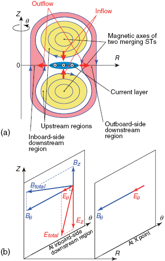
Figure 1. (a) Schematic of magnetic reconnection in plasma merging on a poloidal (R–Z) cross-section. (b) Relationship between the magnetic and electric fields at the inboard-side downstream region and X point of magnetic reconnection with a guide field.
Download figure:
Standard image High-resolution imageOn the other hand, the toroidal magnetic fields involved in the two ST plasmas are in parallel and do not reconnect, usually called a 'guide field'. The guide field is considered to qualitatively change the reconnection process because the charged particles are magnetized even at the neutral X point of the reconnection. It should be noted that the reconnection electric field is mostly parallel to the magnetic field in the vicinity of the reconnection X point, resulting in particle direct acceleration along the magnetic field line by the reconnection electric field [10–12]. In steady reconnection with no guide field, the ions achieve a larger portion of the released magnetic energy because the reconnection outflow velocity is described as an E × B drift. While in the reconnection process in the presence of a high guide field, electrons are significantly accelerated along the magnetic field line and will achieve a large energy from the reconnection electric field  . The relationship between the magnetic field and electric field is illustrated in figure 1(b). At the reconnection X point where no poloidal magnetic field exists, the reconnection electric field and magnetic field are in parallel and significant electron acceleration is expected. At the inboard-side downstream region where the reconnected magnetic field has an axial (Z−) component
  , the reconnection electric field component parallel to the magnetic field line will accelerate electrons and ions in opposite directions and then charge separation in the axial direction takes place. The steady state of the guide field magnetic reconnection is established when the reconnection electric field component parallel to the magnetic field line is cancelled by the static electric field generated by the charge separation in the downstream region. In this saturation stage, the total electric field is orthogonal to the total magnetic field as shown in figure 1(b) and the plasma flows in the radial (R−) direction by E × B drift. Hence, the electron acceleration effect is considered to survive only in the vicinity of the reconnection X point.
With regard to the ST start-up technique, it is necessary to achieve a high plasma current, and high density and high electron temperature plasma that is sustained by additional heating/current drive methods such as neutral beam injection. In the MAST experiment [13], the merging formation of ST plasma has demonstrated the capability of initial electron heating up to 1 keV at the reconnection point due to reconnection current diffusion, electron parallel acceleration, or other possible reasons, however, the heating mechanism has not yet been verified in laboratory experiments.
The merging start-up method for ST plasma is also being developed in the UTST device [14]. The feature of this device is that all the PF coils are located outside the vacuum vessel. The inductive formation of the initial STs and electron/ion heating effect were investigated [14], but the previous experimental results showed that the ions are more effectively heated than the electrons, similar to the magnetic reconnection of the anti-parallel magnetic field [15]. However, the magnetic reconnection process in the merging formation of the ST plasma includes large guide (toroidal) magnetic field  , and electron energization by direct acceleration parallel to the magnetic field line may work as a heating source of electrons.
In this research, we focused on the generation of energetic electrons during high guide field reconnection, which may be responsible for the observed electron heating during ST merging formation. A fast imaging diagnostic of soft x-ray (SXR) emission from the reconnection region of merging two ST plasmas was equipped on the UTST device and a spatiotemporal profile of the fast electrons generated was observed. The experimental results show that electron acceleration takes place not only near the X point but also transiently in the inboard-side downstream region until the static electric field grows and balances the reconnection electric field.
2. Experimental setup
The merging technique requires two initial plasma tori with closed flux surfaces. Figure 2 shows the cross-sectional view of the UTST device. Two ST plasmas are formed in the upper and lower sections of the device by using PF coils #2 and #4. The produced two ST plasmas approach each other and merge at the center of the device. In figure 2, the experimentally observed poloidal magnetic surfaces during the merging phase are shown by black curves, together with the toroidal current density  indicated by color-coding. Radially elongated current layer (blue region) is formed between the two upstream regions of the initial STs.
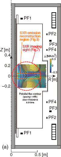
Figure 2. Cross-sectional view of the UTST device. Observed poloidal flux surfaces (black lines) and toroidal current density (color) are also shown.
Download figure:
Standard image High-resolution imageDuring ST merging start-up, it is expected that electrons are effectively accelerated near the reconnection point where the reconnection electric field  is almost parallel to the magnetic field. This electron parallel acceleration will contribute to electron heating during merging start-up. In order to observe the temporal and spatial distribution of the generated energetic electrons, the SXR emission profile was observed by a fast imaging system equipped on the UTST device.
The SXR fast imaging system consists of a pinhole with absorption filter (Mylar 1 µm) whose transmission edge is about 100 eV, a two-stage microchannel plate (MCP) with a phosphor plate, and a vacuum window through which the SXR image on the phosphor plate is monitored by a fast camera. In this experiment, the image was taken with a frame rate of 210 kfps (shutter speed of ~3.15 µs).
Figure 3(a) shows the SXR emission from the reconnection region observed from an upward view as indicated in (b). Intensive SXR were emitted from a ring-like region located inside the reconnection current layer. Since the SXR emission showed a good axisymmetry, the imaging system was then re-equipped on the equatorial plane of the merging STs to view the reconnection region from a tangential direction as indicated in figure 4 of the horizontal cross section of the UTST device.
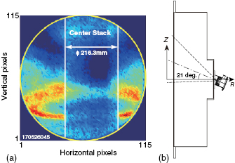
Figure 3. (a) SXR emission from the reconnection region observed from an upward view as indicated in (b).
Download figure:
Standard image High-resolution image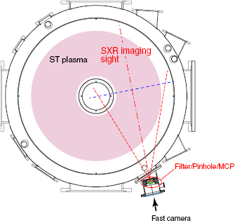
Figure 4. SXR fast imaging equipment and its field of view on the midplane (Z = 0) of the UTST device. The upper and lower limits of sight on the poloidal cross-section (blue line) are about z = ± 270 mm.
Download figure:
Standard image High-resolution imageNine radial arrays of pickup coils are inserted into the plasma with axial spacing of ΔZ ~ 5–6 cm to measure the 2D magnetic field profile of the merging STs. Each radial array has nine pickup coils for the axial magnetic field component Bz and nine pickup coils for the toroidal magnetic field component Bθ with a radial spacing of ΔR = 7 cm. They cover the central area (−0.23 < Z < 0.23 m, 0.11 < R < 0.67 m) of the device as shown in figure 2. From the measured Bz, the poloidal magnetic flux Ψ, toroidal electric field Eθ, and toroidal current density  are calculated under the assumption of axisymmetry.
The working gas used in this experiment was helium. Typical plasma parameters are as follows: major and minor radii: 0.35 m and 0.2 m, respectively; plasma current: ~100 kA; toroidal magnetic field at the axis (or at the reconnection X point): ~0.25 T; poloidal (reconnecting) magnetic field: ~0.01 T; plasma density: <5 × 10¹⁹ m−3; ion and electron temperatures in the initial STs: ~10 eV; ion and electron temperatures after merging: ~50 eV and ~20 eV, respectively.
3. Experimental results
3.1. Overview of the magnetic reconnection process during ST merging
Figure 5(a) shows the time evolutions of the plasma current of the ST merging formation with and without the internal magnetic probe arrays. Since the discharge duration in this experiment was so short, perturbation by the probe arrays was negligible. During the ramp-up phase of the plasma current, merging of the two ST plasmas takes place within short period of <100 µs. Figure 5(b) shows the evolution of poloidal magnetic fluxes at the reconnection X point and at the upstream region. In this plot and hereafter, the horizontal axis is taken from the start time of the merging. Note that the upstream flux should be evaluated as the maximum value at the magnetic axis of the initial ST plasma, but the magnetic axis was not within the magnetic measurement area in the initial phase of merging (indicated by the dotted line). The magnetic flux at the X point gradually increased through magnetic reconnection and finally reached the same value as the flux at the upstream region when the merging process was completed. The time derivative of the poloidal magnetic flux yields one-turn loop voltage, which induces the toroidal reconnection electric field Eθ as shown in figure 5(c). In these experiments, an electric field up to 70 V m−1 was observed. Figure 5(d) shows the time evolution of the current density j θ inside the reconnection current layer. During the ST merging formation, both the reconnection electric field and the current density kept a high value for more than 30 µs in the later merging phase.

Figure 5. Time evolutions of (a) plasma current, (b) poloidal magnetic fluxes at X point and at upstream region, (c) reconnection electric field, (d) reconnection current density, and (e) SXR intensity emitted from the reconnection and the downstream regions. The gray area in each plot indicates the standard deviation between several discharges.
Download figure:
Standard image High-resolution imageSXR (>100 eV) intensity emitted from the reconnection and the downstream regions revealed a rather different time evolution from these reconnection parameters. As shown in figure 5(e), SXR was mostly emitted in the middle merging phase of 40 < t < 60 µs. Negligible emission was observed in the latter merging phase of t > 60 µs while the reconnection electric field was still kept high. Previous Thomson scattering measurements in the UTST merging experiment had shown that the electron temperature during the merging start-up increased up to 25 eV in the vicinity of the X point [16]. The measured electron temperature indicates that the bulk electron heating was not large enough to account for the SXR burst observed in the middle merging phase. Note that the Thomson scattering measurement system equipped on the UTST device made a measurement of electron temperature perpendicular to the toroidal magnetic field. Figure 6 shows the dependency of the peak value of the SXR emission on the toroidal (guide) magnetic field  . More intense SXR emission was observed during magnetic reconnection with a higher guide field, which extends the connection length for traveling electrons in the toroidal direction. Thus, the SXR burst observed in the merging start-up of the ST suggests generation of energetic electrons which have a large velocity parallel to the toroidal magnetic field as a result of direct acceleration by the toroidal reconnection electric field predicted by some numerical studies.

Figure 6. Dependency of peak SXR intensity on the toroidal magnetic field.
Download figure:
Standard image High-resolution image3.2. SXR fast imaging measurement
Figure 7(a) shows the raw image obtained by the pinhole type SXR fast imaging system at the middle phase of the ST merging start-up from the tangential view. The SXR emission distribution consisted of some regions related to plasma merging and magnetic reconnection. The emission region indicated by magenta ellipses are attributed to the core regions of two STs in the upstream regions. Figure 7(b) shows the calculated projection image of the assumed upstream STs' magnetic axes (R = 430 mm, Z = 150 mm and R = 430 mm, Z = −200 mm, respectively) onto the image plane of the MCP surface through a pinhole. The two curved regions of observed SXR emission (magenta ellipses in figure 7(a)) show a similar configuration to the calculation result, suggesting that they reflect a higher pressure at the ST core regions and are not related to the reconnection process.
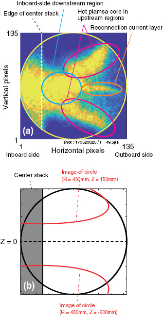
Figure 7. (a) Raw image of SXR observed from a tangential view. (b) Expected image of two circular emission regions projected onto the MCP surface.
Download figure:
Standard image High-resolution imageBetween these upstream regions, a thin emission region was formed near the reconnection current layer as indicated by the orange ellipse. The largest emission came from the inboard-side downstream region as indicated by the blue ellipse. These two emission regions are the product of magnetic reconnection with a guide field. To achieve the spatiotemporal profile of generated fast electrons, reconstruction of the SXR local emission profile was carried out. Since the reconnection layer formed between two initial STs was narrow in the vertical (axial) direction, an Abel inversion technique was employed to reconstruct the local emission profile for the raw image data near the midplane (nearly-horizontal line-of-sights, −50 < Z < 50 mm).
In the ST merging start-up experiment, a large part of the SXR emission was observed in the middle phase of the guide field reconnection. Figure 8 shows the evolution of reconstructed SXR emission profiles in two merging cases. One is the ST merging with the positive toroidal magnetic field (a)–(e), and the other is the ST merging with the negative toroidal magnetic field (f )–(j ). According to the SXR emission profiles, the middle phase can be divided into two stages. In the early stage of the middle phase, the SXR emission in both the toroidal magnetic field polarity cases spread widely in the inboard-side downstream region. The reconnection electric field had only a toroidal component in the ST merging case, and a large component of the electric field parallel to the magnetic field line in the inboard-side downstream region served to accelerate electrons along the field lines.
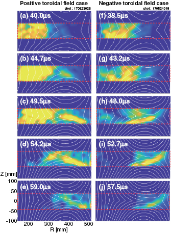
Figure 8. Evolutions of SXR emission profiles from two ST merging configurations. (a)–(e) ST merging with positive toroidal magnetic field and (f )–(j ) with negative toroidal magnetic field. Poloidal flux surfaces are over-plotted by white lines.
Download figure:
Standard image High-resolution imageThen in the late stage of the middle phase at t ~ 50 µs (figures 8(c), (d), (h) and (i)), SXR emission was found inside the current layer near the X point. A distinguishing feature was that the local emission geometry changed depending on the sign of the toroidal magnetic field of the merging STs. When a positive toroidal magnetic field was applied, the SXR emission was localized on two separatrix arms from the upper left to lower right, as shown in figures 8(c) and (d), while the SXR emission was found on two arms from the lower left to upper right for the negative toroidal magnetic field case as shown in figures 8(h) and (i). The emission region in each case agrees with the magnetic field lines on which the toroidally accelerated electrons at the reconnection point will move, which is consistent with the quasi-steady phase in the particle simulation results (e.g. [12]).
Since a high toroidal reconnection electric field  was still induced at the X point and the downstream regions in this late stage, the extinction of SXR emission from the inboard-side downstream region is possibly due to the reduction or cancelation of the reconnection electric field component parallel to the magnetic field line by the charge separation, mostly due to the electrons' motion [17] as shown in figure 1(b) (left).
The SXR emission from the downstream region is considered to be suppressed by the charge separation. The time constant to establish the charge separation is estimated as the travelling time of the electrons along the field lines in the downstream region. The high toroidal field in the inboard-side downstream region prolongs the connection length between the upper and lower areas as long as 2–10 m, resulting in the long travelling time of 1–5 µs, which is comparable with the duration of the SXR emission (~20 µs) from the inboard-side downstream region observed in the experiment.
To investigate the charge separation effect on the electron acceleration, the axial electric field  was measured in the limiter configuration experiment. Four inboard-side limiters made of stainless steel plates with a width of 4 cm were equipped on the center stack with a 90° separation in the toroidal direction. In contrast to the center stack, the limiters do not affect the temporal change of the PF because they have toroidally separated structure. The charge separation is expected to be suppressed when the reconnected field lines contact with the limiters.
The axial electric field  was calculated from the difference in the floating potential measured at two axially separated locations by Langmuir probes (R = 220 mm, Z = ± 40 mm). Figures 9(a)–(d) show the time evolutions of the plasma current, reconnection electric field
  , SXR emission, and axial electric field
  , respectively. The installation of limiters did not make significant changes on (a) the plasma current and (b) the reconnection electric field, but provided a large enhancement on (c) the SXR emission. This change is considered to be caused by the variation of the charge separation condition in the downstream region. The axial electric field
  with a limiter case was kept small until t ~ 50 µs, and then started to increase rapidly and reached ~40 times as high as the toroidal reconnection electric field,
  , which was ~100 V m−1 at the time when the maximum SXR emission was observed (t ~ 60 µs). This axial electric field was large enough to cancel the parallel component of the reconnection electric field because the ratio of toroidal to poloidal magnetic field was about 30 in the inboard-side downstream region. Figures 9(e) and (f) show the poloidal magnetic surfaces at t = 40 µs and 60 µs, respectively. The magnetic field line which passes the Langmuir probe position connects with the limiter region (indicated in blue) at t = 40 µs, resulting in suppression of the charge separation along the field line by the shorting effect of limiters. In the latter timing at t = 60 µs, the accumulated reconnected flux made the field lines more straight in the axial direction and that which passed the Langmuir probe positions did not connect with the limiters. Hence, it is considered that the axial electric field quickly grew at the Langmuir probe position. It is concluded that the electron acceleration in the downstream region was suppressed due to the axial component of the static electric field generated by the biased electron density profile. In other words, a larger part of the released magnetic energy could be converted to electron energy and a higher electron temperature ST could be formed by the merging technique if the downstream conditions were adequately controlled.
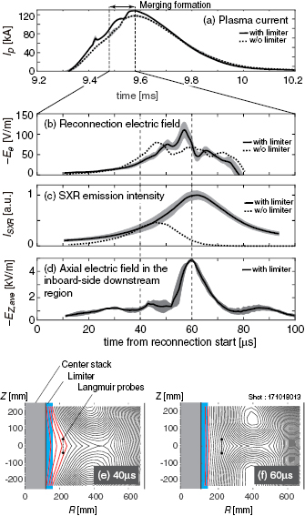
Figure 9. Time evolutions of (a) plasma current, (b) reconnection electric field, (c) SXR intensity emitted from the reconnection and the downstream regions, and (d) axial electric field measured in the inboard-side downstream region for ST merging with inboard-side limiters. Poloidal flux surfaces at two different timings are shown in (e) and (f ) together with the location of the Langmuir probes.
Download figure:
Standard image High-resolution image4. Discussion
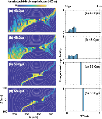
The spatial profile of SXR emission suggests the location of energetic electrons generated by parallel acceleration. Since the electron acceleration occurs within several microseconds, which is much quicker than the merging process, we can simulate the generation process of energetic electrons by using a test particle calculation. Figures 10(a)–(d) are the test particle calculation results based on the experimentally measured magnetic field ( ,
,  ,
,  ) and electric field (
 ) at different timings. The axial electric field was not formed for the early two timings (a) and (b). Both the electrons at the X point and the electrons in the downstream region are significantly accelerated by the reconnection electric field. They are accelerated along the field lines and quickly achieve a kinetic energy higher than 100 eV. The energetic electrons spread largely in the inboard-side downstream region, partly because the toroidal field is much stronger there than at the outboard side. At later timings, the axial electric field grew and cancelled the parallel electric field induced by guide-field magnetic reconnection. The test particle calculation (c) and (d) shows the energetic electrons are localized on two separatrix arms showing a good agreement with experimental results (figures 8(h) and (i)).
Figure 10. Results from the test particle calculation based on the experimentally measured magnetic and electric fields. Spatial distributions of energetic electrons (>100 eV) at different timings are shown in (a)–(d). (e)–(h) The distribution of energetic electrons as a function of the poloidal magnetic flux normalized to that at the magnetic axis of the merged ST.
Download figure:
Standard image High-resolution image
The accelerated electrons will mostly move along the reconnected field lines because the drift velocities are much smaller than the parallel velocity. Therefore the spatial distribution of the generated energetic electrons is important for evaluating the electron heating effect during ST merging formation. Figures 10(e)–(h) show the energetic electron distribution profiles as a function of the magnetic flux normalized to that at the magnetic axis of the merged ST. Since the electron acceleration takes place in the downstream and reconnection separatrix regions, the energetic electrons exist on the outer flux surfaces near the plasma edge.
The experimental results also show a similar tendency. The SXR burst was observed only in the middle merging phase, indicating that the main part of the energetic electrons were formed when 'outer' magnetic fields reconnected. This trend does not agree with the electron temperature profile of the merged ST [13, 16]. One problem is that the SXR emission immediately vanished in the latter merging phase. This result suggests that the accelerated electrons in middle merging phase might have quickly escaped from the ST plasma region. In the present UTST experiment, many internal probes were inserted into the plasma region and these resulted in harmful effects on the energetic electrons. The axial electric field in the downstream region should be controlled to achieve a more effective electron acceleration condition. Further investigation and development are required to utilize this electron acceleration as an electron heating source during ST merging start-up.
5. Summary and conclusion
For the purpose of acquiring high electron temperature ST plasma without use of the CS coil, the merging start-up method has been developed. One of the possible mechanisms to heat the electrons is electron parallel acceleration provided by the magnetic reconnection in the presence of a high guide field. Detailed observation of the energetic electron generation process was carried out. Experimental results from SXR fast imaging showed that energetic electrons (>100 eV) were widely generated in the inboard-side downstream region in the early stage of the middle merging phase before the static electric field was generated by axial charge separation in the downstream region. In the late stage of the middle merging phase, however, the energetic electrons were only generated along the two arms of the reconnection separatrix because the parallel component of the reconnection electric field in the downstream region was cancelled by charge separation. It was found that the electron acceleration could be enhanced by adequate control of the downstream condition, e.g. moderation of the charge separation.
In the present UTST experiment, the observed energetic electrons do not directly provide the origin of electron heating at the magnetic axis of the merged ST as observed in MAST [13] because the fast electrons are localized on the outer flux surfaces. Further investigation of the transport and thermalization of these fast electrons, as well as development of a downstream condition controlling method, are required to evaluate the electron heating during merging ST start-up.
Acknowledgments
This work was supported by Grants-in Aid for Scientific Research (KAKENHI) 15H05750, 15K14279, 26287143, 22686085, and NIFS Collaboration Research programs NIFS18KBAR022, NIFS17KNWP006, NIFS15KBAR012, NIFS14KNWP004.