


Abstract
The capacitively-coupled combline (CCC) antenna has been developed for current drive by the lower hybrid wave (LHW) on the TST-2 spherical tokamak. The combline antenna was developed to satisfy the requirements of high directionality, low reflectivity, and simple feeding. Since the combline antenna makes use of mutual coupling between neighboring elements, only the first and the last elements are connected to external feedlines. RF powers and power densities of the order of 100 kW and 1 MW m−2 can be achieved easily in small antennas of the order of 0.1 m2. The two CCC antennas installed in TST-2 (outboard-launch and top-launch) excite toroidal refractive index ( ) spectra peaked around five with the frequency of 200 MHz. Wave excitation calculation using a finite element code shows that the excited power of the
  LHW component increases rapidly when the plasma cutoff density layer (where
  m−3) becomes closer than 27 mm from the antenna surface, in agreement with experiment. Experimentally, the density profile in front of the antenna can be controlled by adjusting the side limiter location or antenna-plasma distance, and should be optimized for antenna-plasma coupling, since too high coupling results in a broadened and less directional
  spectrum, and too low coupling results in a less efficient power coupling. Using these antennas, successful ST plasma start-up and
  ramp-up to over 25 kA (about 1/4 of the nominal
  for OH operation) have been achieved with RF power of less than 100 kW in about 40 ms.
Export citation and abstract BibTeX RIS
1. Introduction
The spherical tokamak (ST), characterised by low aspect ratio (A = R/a < 2), has the attractiveness of stable operation at high  , but it is considered impractical to realize a compact ST reactor unless the central solenoid (CS) is eliminated [1]. Even for conventional tokamaks, the elimination of CS is desirable for achieving sufficiently low A (2–2.5) to take advantage of improved
  limit, and to ensure engineering feasibility to operate at sufficiently high toroidal field [2]. In either case, tokamak operation without the CS is needed. Non-inductive plasma start-up experiments using the LHW are being conducted on TST-2 [3]. Successful ST plasma formation and Ip ramp-up to substantial levels (about 1/4 of the nominal
  for OH operation) have been achieved using CCC antennas [4].
In order to excite a highly directional wave required for efficient current drive, an antenna array consisting of many elements (typically about ten) is necessary, but it is impractical to feed each of these elements independently in a device with limited accessibility. The combline antenna [5] was proposed to satisfy the requirements of high directionality, low reflectivity, and simple feeding. Since the combline antenna makes use of mutual coupling between neighboring elements, only the first (input) and the last (output) elements are connected to external feedlines and the others are excited passively. Inductively-coupled combline (ICC) antennas have been used successfully on JFT-2M [6], and are either being used or planned on DIII-D [7], KSTAR [8, 9], WEST [10], and DEMO [10, 11].
2. Travelling wave antennas used on TST-2
Three types of combline antenna were used on TST-2: 11-element ICC antenna [12], 13-element CCC antenna (outboard-launch) [13], and six-element CCC antenna (top-launch) [14]. The ICC antenna excites the fast wave with the RF electric field polarized in the poloidal direction, whereas the CCC antenna excites the LHW with the RF electric field polarized in the toroidal direction. Photographs of the two CCC antennas and a simplified circuit diagram are shown in figure 1. Each element is an L-C resonant circuit, coupled to neighboring elements by mutual capacitance, and exhibits a passband characteristic similar to a combline filter. The copper capacitive elements are shaped so that the RF electric field extends well into the plasma. The inductive elements for the outboard-launch antenna consist of two half-turn loops (one on each end of capacitive element, as shown in figure 2) and are covered so neighboring elements do not couple inductively to each other and the RF magnetic field does not extend into the plasma. The inductive elements for the top-launch antenna consist of two shorted stubs on each end of capacitive element, oriented away from the plasma, as shown in figure 3. Faraday shield is not necessary. The two CCC antennas installed in TST-2 excite toroidal refractive index ( ) spectra peaked around five with full width at half maxima of around 2, where
  . Using these antennas, ST plasmas have been formed and
  has been ramped up to 25 kA (outboard-launch) and 27 kA (top-launch) with RF power of approximately 100 kW in about 40 ms. The highest power and power density achieved are 120 kW and 0.75 MW m−2 for outboard-launch, and 90 kW and 1.1 MW m−2 for top-launch. These levels are not yet limited by antenna power handling or transmitter capability.
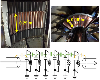
Figure 1. Outboard-launch CCC antenna (top left) and top-launch CCC antenna (top right) installed in TST-2, and a circuit diagram of the CCC antenna (bottom).
Download figure:
Standard image High-resolution image
Figure 2. Single end element of the outboard-launch CCC antenna.
Download figure:
Standard image High-resolution image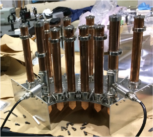
Figure 3. Top-launch CCC antenna assembly.
Download figure:
Standard image High-resolution image3. Modelling of CCC antennas
The electrical characteristics of the antennas and the excitation of the LHW can be modelled by finite element codes such as COMSOL Multiphysics [15] (examples are shown in figures 4 and 5). The plasma is modelled as a dielectric material with cold plasma dielectric tensor. Subsequent wave propagation, absorption, and evolution of the electron distribution function (from which the driven current can be evaluated) are modelled by either a full-wave code or ray-tracing code coupled with a Fokker–Planck code, such as GENRAY [16]/CQL3D [17]. Wave excitation calculation using COMSOL shows that the excited power of the  LHW component increases rapidly when the plasma cutoff density layer (where
 ![$ \newcommand{\pow}[1]{\times 10^{#1}} n_e = 5\pow{14}~{\rm m}^{-3}$](https://content.cld.iop.org/journals/0029-5515/59/6/066004/revision2/nfab0f61ieqn014.gif) ) becomes closer than 27 mm from the antenna surface, in agreement with experiment. The density profile was measured in front of the outboard-launch antenna in the absence of RF power. The density at the leading edge of the side limiters of the antenna (at R = 585 mm) was in the range
) becomes closer than 27 mm from the antenna surface, in agreement with experiment. The density profile was measured in front of the outboard-launch antenna in the absence of RF power. The density at the leading edge of the side limiters of the antenna (at R = 585 mm) was in the range ![$ \newcommand{\pow}[1]{\times 10^{#1}} \pow{15}$](https://content.cld.iop.org/journals/0029-5515/59/6/066004/revision2/nfab0f61ieqn015.gif) m−3 to
m−3 to ![$ \newcommand{\pow}[1]{\times 10^{#1}} \pow{16}$](https://content.cld.iop.org/journals/0029-5515/59/6/066004/revision2/nfab0f61ieqn016.gif) m−3, and the density decay length was of the order of 10 mm. A reliable density profile could not be measured in the presence of RF power. However, in order to reproduce the measured RF power transmission coefficient through the antenna (typically −20 dB) by COMSOL calculation, it was necessary to assume the density to drop by a factor of ten in 10 mm. Such a sharp density in front of the antenna may be caused by the ponderomotive force. Experimentally, the density profile in front of the antenna can be controlled by adjusting the side limiter location or antenna-plasma distance, and should be optimized for antenna-plasma coupling, since too high coupling results in a broadened and less directional
m−3, and the density decay length was of the order of 10 mm. A reliable density profile could not be measured in the presence of RF power. However, in order to reproduce the measured RF power transmission coefficient through the antenna (typically −20 dB) by COMSOL calculation, it was necessary to assume the density to drop by a factor of ten in 10 mm. Such a sharp density in front of the antenna may be caused by the ponderomotive force. Experimentally, the density profile in front of the antenna can be controlled by adjusting the side limiter location or antenna-plasma distance, and should be optimized for antenna-plasma coupling, since too high coupling results in a broadened and less directional  spectrum, and too low coupling results in less efficient power coupling, which necessitates recirculation of the transmitted power.

Figure 4. LHW excited by the outboard CCC antenna (left) and top-launch CCC antenna (right), calculated by COMSOL.
Download figure:
Standard image High-resolution image
Figure 5. Passband characteristics of the outboard-launch CCC antenna without vacuum feedthrough and without plasma. Measured voltage transmissivity and reflectivity are compared to those calculated by COMSOL. Reproduced with permission from [18].
Download figure:
Standard image High-resolution imageFor the top-launch antenna, the distance between the cutoff density layer and the antenna was scanned to investigate the change in toroidal wavenumber spectrum (see figure 7 in [19]). The dependence of antenna transmissivity and reflectivity on the distance between the antenna and the cutoff density layer is shown in figure 6. As the cutoff layer become closer, the transmissivity decreases, which indicates that the injected power into the plasma increases. In the top-launch antenna, the phase shift from the neighboring element is about 90 degrees on average, and it is known that the optimum distance is about 17 mm–27 mm (as reported in [19], distances closer than 17 mm results in increased counter-current-drive component in the wavenumber spectrum, while distances greater than 27 mm result in poor antenna-plasma coupling and reduced wave excitation efficiency). Figure 6 shows that the corresponding transmissivity is in the range 18%–40%, which corresponds to an attenuation of −0.66 dB to −1.24 dB per element.
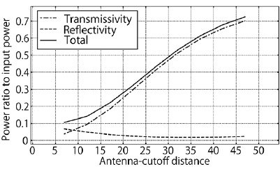
Figure 6. Transmissivity, reflectivity, and their total from COMSOL calculation as a function of the distance between the top-launch antenna and the cutoff density layer.
Download figure:
Standard image High-resolution image4. Antenna tuning
Antennas were initially tuned in atmosphere so that the passband is nearly centered around 200 MHz used in experiments, and the reflection at this frequency is nearly zero by adjusting the RF feeding point to where the input impedance is 50  (see figure 5). The phase shift between adjacent elements (and therefore the excited toroidal wavenumber spectrum) is determined by the location of 200 MHz within the passband. It is useful to utilize a circuit simulator code such as LTspice [20] (which has less details compared to COMSOL, but runs much faster) to guide the tuning process. For example, a single frequency COMSOL calculation takes about 15 min and requires 100 GB of memory, but LTspice requires only 2 GB of memory and can run 10 000 frequencies in 5 s.
An LTspice model of the top-launch antenna is shown in figure 7. The model shown in figure 7 includes capacitive elements, stainless steel walls (back wall and side walls) and inductors (two shorted stubs of variable lengths per capacitive element). The stubs are modelled by C and L for each centimeter of the coaxial line. Capacitances from each capacitive element to the neighboring element and to the back wall, and capacitances from the end elements to the side walls are fixed, whereas the length of each stub (from the capacitive element to the short) and the positions of the input and output ports are variable. The stub length for the two end elements are shorter than those for the middle four elements by about 10%. Tuning of the antenna proceeds as follows: first, the stub lengths are adjusted so that the passband is roughly centered around 200 MHz and the phase shift corresponds to the desired wavenumber. Second, the stub lengths of the end elements are adjusted so that the reflection minimum is located at 200 MHz. Finally, the height of the input/output ports are adjusted to minimize the reflectivity at 200 MHz.
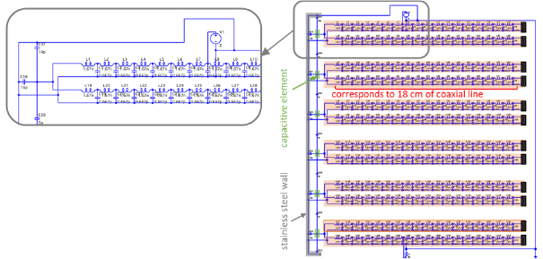
Figure 7. LTspice model of the top-launch CCC antenna. The inductances and the capacitances of lumped constant circuits arranged in a row represent the discretization of the coaxial line. In this figure, the discretizing scale is 1 cm.
Download figure:
Standard image High-resolution imageThe plasma load was simulated by a thin resistive film (300  square) experimentally. The spikey structure in the reflected power disappears and the transmitted power decreases as the film approaches the antenna surface, as shown in figure 8. COMSOL calculations show that the transmitted power exiting the output port is −2 to −3 dB of the input power when the plasma cutoff layer is placed 51 mm and 36 mm in front of the top-launch antenna, but it decreases to −7 dB when the cutoff layer is placed 28 mm in front of the antenna, indicating that the propagating region inside the plasma (with density greater than the cutoff density) should be placed 30 mm or less in front of the antenna for effective wave excitation. This is in agreement with the experimental result obtained using a resistive film.
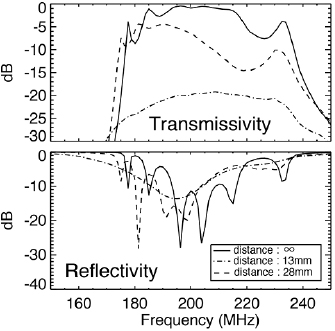
Figure 8. Dependences of transmissivity and reflectivity characteristics on the distance between the antenna surface and the resistive film (no film, 13 mm, and 28 mm). Reduction of transmission corresponds to LHW excitation in the plasma.
Download figure:
Standard image High-resolution image5. Experimental results obtained with CCC antennas
The CCC antennas were used successfully to perform plasma start-up and plasma current ramp-up experiments on TST-2. Typical waveforms of plasma current ramp-up experiment are shown in figure 9. Details of comparison between the top-launch and outboard-launch antennas are reported in [19]. Note that top-launch with counter-clockwise  is equivalent to bottom-launch with clockwise
  . Although the density is not perfectly matched in all cases, it can be seen that generally higher
  can be obtained at higher
  , and with top-launch CCC (for both directions of
  ).
).
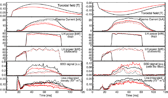
Figure 9. Waveforms of plasmas driven by LHW excited by CCC antennas. Clockwise (left) and counter-clockwise (right) toroidal field  , high
  (black) and low
  (red), top-launch (solid line) and outboard-launch (dashed line).
Download figure:
Standard image High-resolution imageThe dependences of the driven  on
on  and on the location of the top limiter are shown in figure 10. In addition to the generally increasing trend of
  with
with  , it can be seen that the upper limit of
  is higher when the top limiter location is higher, which enables plasmas with larger cross section to be formed. For outboard launch, the highest
  was 21 kA when the limiter position was at z = 350 mm and 25 kA when the limiter position was at
  . The maximum
  is expected to be about 23 kA when the limiter position is at
  . Recently, the top-launch antenna was modified (stubs were shortened) and re-installed so the top limiter is at
  . Discharges have not recovered from the extensive vacuum break, but maximum
  of 17 kA and 24 kA have been achieved with outboard-launch and top-launch antennas, respectively. With further conditioning, improvement in the maximum
  is expected.
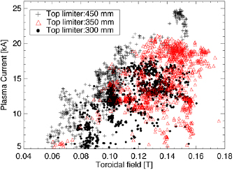
Figure 10. Dependences of the driven  on
on  and on the location of the top limiter. Higher top limiter location indicates that plasmas with larger cross section can be formed.
Download figure:
Standard image High-resolution image ramp-up by top-launch LHW alone (without the outboard-launch LHW) was also attempted, but it was found to be more difficult compared to the outboard-side injection (see figure 11). Although the toroidal component of the index of refraction
  of the LHW excited by the outboard-launch antenna (at
  ) and the top-launch antenna are similar (peaked around
  ), the toroidal mode number n is different, n = 13.0 for outboard launch and n = 5.9 for top launch, so the phase velocity of LHW in the plasma (at the same R) is faster for top launch. Therefore, absorption by Landau damping during the initial phase, where
  and electron temperature are low, is less efficient for top launch. Another reason of difficulty for top launch during the initial phase is that a careful control of the plasma vertical position is required since the plasma is not centered on the midplane.
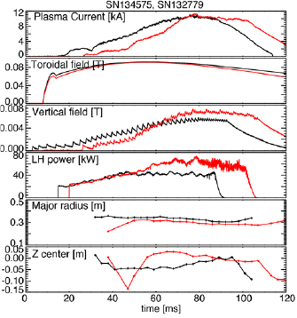
Figure 11. Comparison of plasma start-up between outboard launch (black) and top launch (red). Plotted parameters are, from top to bottom:  ,
,  at
at  (nominal plasma center), vertical magnetic field, LHW input power from the outboard-launch antenna or the top-launch antenna, major radius of the geometric plasma center and the vertical position of the geometric plasma center.
Download figure:
Standard image High-resolution imageBased on this observation, it was decided to shorten the stubs of the top-launch antenna so the top limiter can be moved higher. LTspice simulation was used extensively to optimize the design. The diameter of the inner conductor of the coaxial line was reduced to increase the inductance per unit length. By increasing the ratio of the outer conductor radius to the inner conductor radius from 2.3 to 5.7, it was possible to shorten the stub lengths by 40% (from 200 mm to 120 mm). The lengths of the stubs and the height of input/output ports were determined following the procedure described in section 4. A comparison of LTspice simulation and measurement of the antenna (without plasma) is shown in figure 12. The agreement is satisfactory.

Figure 12. Passband characteristics of the top-launch antenna with shortened stubs, without plasma. Top (LTspice simulation): transmissivity (black), reflectivity (red), power (solid), and phase (dashed). Bottom (measurement): transmissivity (black), reflectivity (red), and total (chain) powers.
Download figure:
Standard image High-resolution image
6. Conclusions
The CCC antenna was developed for current drive by the LHW in tokamaks. It can excite the LHW with high directionality efficiently with simple feeding with low reflectivity (of the order of 1%). RF powers and power densities of the order of 100 kW and 1 MW m−2 can be achieved easily in small antennas of the order of 0.1 m2, because of the inherently low standing wave ratio. Successful ST plasma start-up and  ramp-up have been demonstrated on TST-2. Antenna characteristics and wave excitation can be modelled by finite element codes such as COMSOL Multiphysics. A circuit model based on LTspice was developed to study parameter dependences of the antenna characteristics efficiently. A procedure for tuning combline antennas has been developed based on such a model.
The use of this type of antenna at higher frequencies is challenging since the antenna size must be reduced. On TST-2, electron pre-heating by 500 MHz LHW is planned to improve power absorption of 200 MHz LHW and the driven current profile. This experiment should give information on the power handling capability at higher frequencies.
Acknowledgments
This work was supported in part by Japan Society for the Promotion of Science: Grants-in-Aid for Scientific Research (S) 21226021 and (A) 21246137; Fusion Energy Sciences: DE-AC03-97ER-54411; National Institute for Fusion Science: NIFS14KOCR001, NIFS18KOAR022 and NIFS16KNWR 002; Japan/US Cooperation in Fusion Research and Development.