


Abstract
Plasma-facing materials and components in a fusion reactor are the interface between the plasma and the material part. The operational conditions in this environment are probably the most challenging parameters for any material: high power loads and large particle and neutron fluxes are simultaneously impinging at their surfaces. To realize fusion in a tokamak or stellarator reactor, given the proven geometries and technological solutions, requires an improvement of the thermo-mechanical capabilities of currently available materials. In its first part this article describes the requirements and needs for new, advanced materials for the plasma-facing components. Starting points are capabilities and limitations of tungsten-based alloys and structurally stabilized materials. Furthermore, material requirements from the fusion-specific loading scenarios of a divertor in a water-cooled configuration are described, defining directions for the material development. Finally, safety requirements for a fusion reactor with its specific accident scenarios and their potential environmental impact lead to the definition of inherently passive materials, avoiding release of radioactive material through intrinsic material properties. The second part of this article demonstrates current material development lines answering the fusion-specific requirements for high heat flux materials. New composite materials, in particular fiber-reinforced and laminated structures, as well as mechanically alloyed tungsten materials, allow the extension of the thermo-mechanical operation space towards regions of extreme steady-state and transient loads. Self-passivating tungsten alloys, demonstrating favorable tungsten-like plasma-wall interaction behavior under normal operation conditions, are an intrinsic solution to otherwise catastrophic consequences of loss-of-coolant and air ingress events in a fusion reactor. Permeation barrier layers avoid the escape of tritium into structural and cooling materials, thereby minimizing the release of tritium under normal operation conditions. Finally, solutions for the unique bonding requirements of dissimilar material used in a fusion reactor are demonstrated by describing the current status and prospects of functionally graded materials.
Export citation and abstract BibTeX RIS

Original content from this work may be used under the terms of the Creative Commons Attribution 3.0 licence. Any further distribution of this work must maintain attribution to the author(s) and the title of the work, journal citation and DOI.
This article was updated on 26 August 2021 to correct the copyright line.
Introduction
The exhaust of power and particles is regarded as one of the ultimate challenges in view of the design of a nuclear fusion demonstration power plant [1–3]. The tolerable peak power load on highly loaded plasma-facing components (PFCs), like the divertor targets, represents a key constraint on the design of a future demonstration (DEMO) reactor and will determine its operating scenario [4]. The performance of such highly loaded PFCs is closely linked to the properties of the materials that are used for its design. A fundamental improvement of the performance of such components can only be achieved by applying advanced materials with improved properties.
This paper starts with a part on the requirements and needs for new materials, in which the capabilities and limitations of tungsten based materials are highlighted and discussed. It is followed by a section that explains the design and material problematics of plasma-facing components (PFC) starting from an ITER-type divertor target 11 , 12 . The final two sections deal with important safety aspects such as loss-of-coolant (LOCA) events and tritium permeation. The following part consists of a selection of current material concepts and development lines that address the beforementioned problems and requirements. These comprise fiber-reinforced composite materials, laminates, mechanically alloyed tungsten, self-passivating tungsten alloys, permeation barrier layers, and functionally graded materials (FGM) for fusion applications.
1. Requirements
In a future DEMO reactor, highly heat-loaded plasma-facing components, like the divertor targets, will have to withstand both severe high heat flux (HHF) loads and considerable neutron irradiation. The HHF loads considered for design specification are <1 MW m−2 for first wall (FW), and 10–20 MW m−2 for divertor components under steady-state operation, and even more severe HHF loads for transient events [5]. Furthermore, it has been predicted that for a DEMO reactor neutron damage levels in a PFC material in the divertor region can reach values up to 6–7 dpa fpy−1 [6, 7] which is a dose high enough to lead to pronounced degradation of material properties. The prime requirements for the materials of highly loaded PFCs are hence a high thermal conductivity, a low sputtering yield, and sufficient mechanical properties even under neutron irradiation.
Material embrittlement due to neutron irradiation is one of the most critical issues. Compared to ITER, the neutron irradiation dose of the DEMO divertor is predicted to be higher by an order of magnitude [8, 9]. Moreover, the pulse duration time of plasma burning in a DEMO reactor will be significantly longer than in ITER. Such a long pulse operation may foster damage such as creep-fatigue or irradiation creep at high temperatures [10–12]. Since the structural performance of the PFC materials will be dictated by temperature-dependent mechanical properties, the impact of thermal boundary conditions (HHF loads and cooling conditions) on the structural behavior needs to be assessed to identify the maximum possible power exhaust capability. In this context, a quantitative assessment and the understanding of failure modes is of importance. Hence, this topic is discussed on the basis of computational studies.
Tungsten and tungsten based materials are considered as top candidates for various fusion applications due to their supreme high temperature properties. They combine a high melting point, high creep resistance, high temperature strength, good thermal conductivity, low vapor pressure and good erosion resistance [13]. However, in contrast to these excellent high-temperature properties, the main disadvantage of the proposed material is its brittleness at low temperatures. W, like most body-centered cubic (bcc) metals, has a characteristic transition from brittle to ductile behaviour taking place at a certain temperature. An exact value of the transition temperature cannot be given, as this quantity strongly depends on the condition of the material (i.e. microstructure and testing direction) [14] and on the strain-rate [15]. Thus, problems might arise during application because the ductile-to-brittle transition temperature (DBTT) can be rather high. This is clearly seen in the results of Charpy tests [16] performed on pure, recrystallized W plate material with the crack orientated perpendicular to the rolling direction, where the transition temperature goes up to 1000 °C and beyond. Further problems arise when W-based materials are exposed to the harsh irradiation environment of the reactor. The ductility degrades even more [17–19]. Different ductilization and toughening strategies are discussed, describing the relevant experimental results. Overall conclusions regarding the applicability of tungsten based materials in future fusion reactors are drawn.
The successful application of W for future fusion reactors will be determined by both a decrease in the DBTT and an increase in the ductility and the fracture toughness. Extensive research is focused on these issues [20, 21] and in principle there are three ductilization strategies: (i) the synthesis of a W solid solution—alloying, (ii) the synthesis of materials with an ultra-fine-grained (UFG) microstructure—nanostructuring, and (iii) the synthesis of W composite materials—materials design.
The only metals that show an unrestricted solid solubility in W are V, Ta, Mo and Nb. Besides these, a few other elements such as Re, Ti and Ir exhibit a limited solubility. Their applicability is restricted to amounts of about 27 at%, 12 at% and 10 at% respectively, due to the formation of different intermetallic phases [21, 22]. In order to ensure that the nuclear waste properties at the end of the lifetime of the respective components are within acceptable limits, a low activation and a rapid decay of the radiation in the case of the activated materials are mandatory. Therefore, for all of the materials in question this is one of the main requirements [23], and can be achieved by the selection of appropriate alloying elements and by controlling the impurities. Since it is well known that Mo and Nb transmute to very long-living radioactive isotopes, they have not been overly investigated for fusion applications. However, a recent publication by Brooks et al [24] indicates the potential use of alternative high-Z materials (including molybdenum and niobium) as an additional option for plasma-facing materials. Their focus is on comparisons to tungsten, taking into account advanced recycling options and activation properties. Nevertheless, the ductilization effect of Mo and Nb on W alloys will not be addressed in this publication. In any case, the decision as to whether elements which transmute into long-living isotopes can be used in a fusion device eventually depends on the acceptance of waste at different activity levels. If comparatively strict requirements are applied, Mo and in particular Nb cannot be used for fusion applications [25, 26].
W–Ti and W–Hf alloys could be a possible option, but they have not been investigated so far, and very little is known about Ti and Hf as alloying elements. To continue, based on experimental observations, Kloop [27] listed Tc, Os and Ru as possible ductilizers for W. However, Os is toxic and too expensive to be considered for fusion applications, Tc is radioactive and does not have stable isotopes, and Ru is a rare metal with a very low abundance. Possible candidates that are discussed in this paper for attempts of W toughening by alloying are Re, Ir, V and Ta.
2. Possible solutions
According to a textbook definition, composites are materials that consist of at least two phases which are separated by an interface and characterised by notably different physical and/or chemical properties [28]. Another characteristic aspect according to this definition is that composite materials exhibit properties that are not depicted by any of the constituents in isolation. Many materials that are well-known to us are effectively composites. This in particular true for various natural biological materials such as wood, bone, or hide [29]. Composites are frequently classified according to the applied matrix material. One example of conventional composites that are widely used for various applications are polymeric matrix composites (PMCs) [30]. Another distinguished class is represented by composites based on ceramic matrix materials (ceramic matrix composites, CMCs) [31], while there is also the category of metal matrix composites (MMCs) [32]. Aside from that, a categorisation of composite materials can also be made according to the reinforcing phases which are used. These reinforcements can be in the form of particles, flakes, whiskers, short fibres, continuous fibres, or sheets. Very often, reinforcements are used in the form of fibres as materials are usually stronger and stiffer in fibrous shape than in any other form [28]. For many years, glass fibres have been extensively used to produce fibre-reinforced materials, but nowadays, there are many other high performance fibres available, e.g. silicon carbide, carbon, or alumina fibres.
The properties of a composite material are determined by the volume fraction, the shape, and the orientation of the reinforcements, as well as the intrinsic properties of the constituents. These circumstances already indicate one of the main advantages of composite materials. The macroscopic behavior of such materials can to a large extent be tailored by customising the microscopic structure of the composite, and thus material properties that cannot be accomplished with monolithic material grades can be realised. Materials with high strength fibrous reinforcements allow the enhancement of mechanical properties like strength, similarly to e.g. carbon fibre-reinforced polymers. Furthermore, fibre reinforcement can provide toughness enhancing mechanisms and increases the overall resistance against fracture of typically brittle materials, similarly as in e.g. ceramic fibre-reinforced ceramics (CMCs). These concepts are presented in detail. The reinforcement of the preferred heat sink material copper with high strength W and SiC fibres allows a significant increase of its strength, especially at elevated temperatures. The toughness of the preferred, but brittle plasma-facing material tungsten can be increased significantly by incorporating W fibres into the material.
Tungsten is considered a primary candidate not only as a plasma-facing, meaning functional material, but also as a structural material for safety-relevant and pressurized parts, like pipes. In particular, the high-temperature concepts of a helium-cooled divertor ask for structural high-temperature components and, therefore, for advanced materials [33–35].
Differently from other body centred cubic (bcc) materials like α-Fe, the mechanical properties of tungsten can be significantly improved by cold working—for example, by cold rolling. One example of such semi-finished products that have experienced high degrees of cold working are W foils. Their excellent mechanical properties are the starting point for the synthesis of tungsten laminates. They are ideally suited for the production of pipes, which have been demonstrated to exhibit exceptional Charpy impact properties, hence ductility at low temperatures. In this context, the question of ductilization mechanisms in laminates is addressed, the current R&D status of tungsten laminates is described, and potential application fields outside of fusion addressed.
Another approach to improve the mechanical properties of tungsten is to go for nanostructures, and mechanical alloying (MA) is the most effective process for this purpose. In this way, intergranular cracking, which is responsible for low temperature embrittlement and recrystallization embrittlement, will be mitigated by reinforcing grain boundaries (GB) of random orientations with high energies. On the other hand, radiation-induced embrittlement will be mitigated by nanostructures that contain a high density of sinks for radiation-induced point defects, such as GBs and dispersoids, so as to annihilate radiation-induced point defects.
Such nanostructures may cause a significant increase in yield stress due to grain size strengthening and dispersion strengthening, and have numerous possible cracking sites of high energy GBs, interfaces between dispersoids and the W matrix, residual pores, etc. In addition, a very high Peierls stress for dislocation motion in W suppresses crack-tip blunting due to difficulty in crack-tip plasticity, and promotes crack initiation and/or propagation along GBs and grain interior. In view of these embrittling effects and the very heterogeneous phenomenon of fracture that will occur even when only one possible cracking site is contained, in order to realize the ductilization of nanostructured W, all of the possible cracking sites, especially GBs and dispersoid interfaces, must be reinforced.
How can such a reinforcement of all of the possible cracking sites in nanostructures be achieved? The best way to answer this question is to go back to the fundamental studies conducted for Mo bicrystals. Intergranular embrittlement is peculiar to the group VI A transition metals such as W and Mo. It is very sensitive to both the GB orientation and the contents and chemical state of interstitial elements like oxygen, nitrogen and carbon at the GBs. Mo is usually prepared in structurally and chemically better controlled states than W, mainly due to a much lower melting point. Therefore, at first we present the essential results obtained from the bicrystal experiments on Mo [36–40]. Then, we will show how the results are applied to ductilization in the nanostructured W materials.
The reinforcement of all of the possible cracking sites requires the use of MA [41], Hot Isostatic Pressing (HIP), and the development of GB Sliding-based Microstructural Modification (GSMM) [42] in the powder metallurgical route. The MA-(HIP)-GSMM is not only the key mechanical process for ductilization in nanostructured W materials, but can also be widely applied to many other nanostructured alloys. MA and GSMM are introduced as the key mechanical processes, as well as the features of nanostructured W materials fabricated by MA-(HIP)-GSMM. Mechanical and plasma-wall interaction behavior and behavior under neutron irradiation of these materials are also addressed.
All present DEMO and subsequent fusion reactor concepts are based on the D–T fusion reaction. Employing tritium in a large-scale facility requires containment of this radioactive hydrogen isotope. For plasma-facing components, the permeation from the plasma chamber into structural materials and coolants is of primary importance. Hydrogen isotope permeation through a material depends on physical and chemical properties. Metals have in general higher permeability than non-metals and ceramics. The surface roughness, the microstructure and the crystallographic phase are also very important factors for the permeability. A good permeation barrier has to fulfill both a low diffusivity and a low solubility of hydrogen. Oxides are promising barrier candidates, due to their high permeation reduction factor. For fusion applications the high thermal stability of several oxides, e.g. Al2O3, is an important advantage, as will be outlined in detail.
Copper or copper alloys and reduced activation ferritic/martensitic (RAFM) steels, e.g. EUROFER97, are primary structural material candidates for the first wall of ITER and DEMO respectively [13, 43]. For protecting first wall material from physical and chemical sputtering by plasma particles [44], pure tungsten is considered as the candidate armor material for the current helium cooled divertor concept [20, 45] and the water-cooled divertor targets for ITER [13]. However, residual stresses, generated from the large mismatch of thermo-physical properties between tungsten and copper (copper alloy) or between tungsten and RAFM steels, may lead to the failure of the PFCs. The application of functionally graded materials (FGM) is considered a good solution for the thermal mismatch problem [46, 47]. Hence, W/Cu FGM and W/EUROFER97 FGM are two main research topics for fusion application, which are discussed as possible solutions to the abovementioned requirements.
Requirements and needs for new materials
3. Capabilities and limitations of tungsten based materials
3.1. Alloys
3.1.1. Tungsten–rhenium alloys.
Re is by far the most important alloying element for W with respect to ductilization. The maximum solubility of Re in W is 37 at% Re at 3000 °C; this decreases with decreasing temperature, reaching 27.5 at% at 1600 °C [48]. W–Re alloys have gained outstanding importance since it was shown that they exhibit a significantly lower DBTT [49], and are even stronger than pure W at high temperatures [50]. Seeing that the main shortcoming of W is its low-temperature brittleness, it is not a surprise that the interest in alloying by Re has considerably increased. Furthermore, Re additions have a beneficial impact on the reduction of the degree of recrystallization embrittlement [51], significantly improve weldability, and when compared to pure W, W–Re alloys show superior corrosion behavior [22].
One of the first investigations of the supreme properties of these alloys was conducted in the mid 1950s by Geach and Hughes [52]. They reported that W–Re alloys show a good temperature strength (that originates from Re) and a very high ductility, that can be related neither to the pure W nor to the Re. The room temperature (RT) ductility of W alloys varies with rhenium content, reaching a maximum at about 30 wt%. They attributed the improvement in low-temperature ductility to the mechanical twinning which allows plastic deformation at low stresses, thus avoiding the increased locking of dislocations at low temperature and high strain rates [49].
A detailed fracture mechanical investigation was performed by Mutoh et al [53], focusing on the fracture behavior of W and its Re alloys (W–5 wt%Re and W–10 wt%Re) at elevated temperatures. The results show that for all three materials KIc is about the same at RT with the values of 12–14 MPa m1/2 [53]. With increasing temperature, Re alloys tend to be tougher up to 1000 °C, when a decrease is observed. Corresponding to the results of the fracture toughness values at RT, fractographic analysis of all the materials reveals a quasi-cleavage brittle fracture. At 800 °C, a ductile dimple fracture is visible on the fracture surfaces of the Re alloys, indicating that the DBTT has already been exceeded. In the case of pure W, the fracture surface still has a dominant quasi-cleavage fracture with no dimples. At very high temperatures, pure W experiences an embrittlement of the intergranular regions and crystal growth due to recrystallization. However, the materials containing rhenium show no significant recrystallization and embrittlement of the grain boundaries, leading to a mild reduction of toughness values. Based on the obtained results, adding Re to W has a beneficial impact on the improvement of the high temperature toughness, as well as on the decrease of DBTT.
In the work of Gludovatz et al [54], the effects of the microstructure and the production route on the fracture toughness of W based materials were investigated. For all materials, as expected, an increase of fracture toughness was observed when raising the temperature. However, W–Re alloys show significantly higher levels of KIc, and more pronounced plastic deformation, in comparison with other materials. Even at room temperature a very distinct plasticity is revealed in electron back scatter diffraction (EBSD) scans, along the crack path of the propagated crack. At higher temperatures, plasticity appears in the wider vicinity of the crack flanks (figure 1).
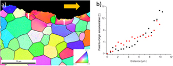
Figure 1. (a) Inverse pole figures compiled by an EBSD scan, showing plastically deformed areas along the crack path (yellow arrow) of W–Re CT specimens tested at 300 °C; the given color code is used for identification of crystallographic orientations of the grains. (b) Misorientation of the two grains is indicated by white arrows.
Download figure:
Standard image High-resolution imageThe main focus in [55] was the investigation of the fracture behavior of W–26Re alloys between RT and 900 °C. The experimental results reveal a high anisotropy of fracture toughness in the case of the as-forged material, where the conditional fracture toughness was changed by a factor of almost two, when changing the crack plane and crack propagation direction with respect to the microstructure. Recrystallized samples are less tough compared to specimens made of rolled material; nevertheless, the fracture toughness values of recrystallized W–Re are well above those of recrystallized pure W. The kind of recrystallization that might happen in future fusion reactors completely changes the microstructure, affects the good mechanical properties, and lowers the fracture toughness. However, in [55] it was shown that even though the fracture toughness is lowered by almost 50% at room temperature and 300 °C, after recrystallization, this material is still superior over pure, recrystallized tungsten, by a factor of three.
So how can this advantageous influence of rhenium alloying to tungsten be explained? What is the mechanism(s) that enhances ductility and toughness, and what kind of physical processes lie beneath this effect?
A decade after the discovery of improved properties for W–Re, Booth et al published a paper reviewing several possible factors that could explain this positive influence [56]. One fact is the promotion of twinning in Re-based alloys with W and Mo, which was identified as a mechanism aiding deformation, e.g. by reducing stress concentrations. However, this cannot be the sole factor making these alloys tough.
Segregation of Re to grain boundaries was also discussed in [56]. At that time, the conclusions were rather drawn indirectly from a change in fracture morphology, going from cleavage fracture for pure materials, to grain boundary fracture for Re alloys. However, two years later Gilbert [57] found a change from grain boundary fracture in unalloyed W to cleavage fracture for Re alloys. From the authors' experience [58] it can be said that it is difficult to link the ratio of inter- to transcrystalline fracture with alloying (or impurity) content. It is influenced to a greater extent by microstructural features such as grain size and grain shape.
Besides the improved properties, many authors mention the solid solution softening phenomenon which can be observed at low temperatures [27, 59, 60]. When adding small amounts of rhenium, there is a significant decrease in hardness. However, this effect diminishes on increasing the Re content and the temperature; it completely disappears above a homologous temperature Tm of 0.16 [27]. The phenomenon of solid solution softening is not peculiar to Re alloys—it is a common feature of bcc materials. Keeping in mind that W–Re alloys also show markedly good mechanical properties at high Re contents and elevated temperatures, there have to be (at least) two mechanisms working that ductilize and toughen these alloys. For applications, the solid solution softening is of less interest, as this effect vanishes for higher temperatures. A thorough review of this effect is given by Pink and Arsenault [59].
What seems to promote these improved mechanical properties of W–Re alloys is assigned to the change in the dislocation properties, in particular screw dislocations of  type. Gröger et al [61] performed computer simulations based on bond order potentials, and showed that
  glide planes are the preferred glide planes for pure W and Mo at low temperatures. An explanation of the Re ductilizing effect was then given by Romaner et al [62] by means of the density functional theory (DFT) calculations of
  screw dislocation in W–Re alloys. It was demonstrated that alloying with Re leads to crucial changes in the interatomic bonding, thereby affecting the screw dislocation core structure. Re additions lead to a pronounced asymmetry in the
  direction. The existence of the transition from a symmetric to an asymmetric core is revealed; this causes a change in the preferred slip plane [62], and has a significant influence on the glide behavior of the dislocation. Whereas the glide in pure W is uniform on one glide plane, the glide plane changes for W–Re alloys, resulting in an overall movement on
  planes. Additions of Re affect not only the slip plane, but also the Peierls stress
  , which is lowered.
  is the shear stress required to make a dislocation glide in an otherwise perfect crystal without the assistance of thermal activation. In agreement with this are the results of many experiments where the plastic behavior and the glide planes of W and various W alloys were investigated [63–65]. At room temperature for pure W, in both
  and
and  slip systems, a slip has been observed. Adding Re promotes slip at room temperature on
  planes. The publication by Li et al demonstrates and explains this increase in number of slip planes, combining both experimental work and computer simulations [66]. Similar simulations were performed for alloys of W with Ta and V, but no change in the screw dislocation core structure was found, which is in agreement with the experimental results collected over the years.
To summarize, the ductilizing effect can be attributed to the change in core symmetry, the decrease of  , and the increase of the number of slip planes. Hence, the origin of this phenomenon is intrinsic, and results from the filling of the d band, which modifies interatomic bonding, leading to enhanced dislocation mobility and improved plastic deformation.
It becomes clear that ductility and toughness enhancement of W by formation of solid solution is possible by the addition of Re. Many experimental results show e.g. improved toughness and lower DBTT, and computational results give the explanation. However, despite the strong technological relevance of the Re ductilizing effect its use is limited by the fact that Re is a rare metal. For fusion energy application, W alloying with Re is inhibited due to the element's low availability. Nevertheless, knowledge on the effect of Re alloying is important for fusion applications. W atoms partially transmute into Re due to neutron irradiation, and therefore materials' properties might change with increasing neutron dosage.
3.1.2. Tungsten–iridium alloys.
Iridium is rarely mentioned in the literature as a typical W alloying element. Nevertheless, its electronic configuration, the neighbourhood to Re in the periodic system of elements and the W–Ir phase diagram indicate some promising effects on W. The solubility of Ir in W decreases with decreasing temperature—the maximum of about 10 at% is at the peritectic temperature (2540 °C) and decreases to about 4 at% at 1810 °C [48].
Luo et al investigated the mechanical properties of W–Ir alloys in two publications in the early 1990s [67, 68]. In the first paper, the scope was the investigation of a solid solution softening mechanism of Ir in W at room temperature [67]. It was deduced that even with small amounts of Ir the properties change noticeably. The concentration of 0.4% Ir corresponds to the maximum in solid solution softening, minimum strength and maximum ductility. In comparison to the alloy containing Re, these effects are more pronounced, and the iridium is shown to be more efficient in terms of solid solution softening.
In the second paper from Luo et al, the investigation of the effects of Ir concentration and the test temperature on the strength and fracture behavior of W–Ir alloys at ultrahigh temperatures was performed [68]. Iridium shows a moderate strengthening effect in the temperature range 2200–2600 K, but with the increase in temperature the effect decreases and finally vanishes at 2600 K. The increase in tensile properties of the alloy is proportional to the concentration of added Ir (see figure 2 in [68]).
As the experimental data for tungsten–iridium systems are limited and very little is known, in order to make final conclusions regarding the beneficial effect of Ir addition, further investigations of mechanical properties are necessary. However, from a technical point of view viz. fusion applications, iridium is assumed not to be significant due to its very low abundance. Yet if about 0.2 at% would be sufficient to obtain a substantial improvement in mechanical properties, then alloying by iridium might be reconsidered for applications in fusion environments.
3.1.3. Tungsten–vanadium alloys.
The W–V system has a continuous series of solid solutions with a bcc structure, occuring between pure V and pure W at all compositions [48]. They exhibit high strength, good fabricability and good corrosion resistance. Experimental results of mechanical properties and the fracture behavior of W–V alloys are scarce. Based on the data from the Charpy impact testing at different temperatures, it seems that alloying W with V is not a promising avenue of toughness and ductility enhancement. No improvement in the DBTT can be observed (figure 2), and for temperatures below 1000 °C when compared to pure tungsten, all depicted alloys are more brittle [21].

Figure 2. Charpy results of pure W, W–Ta, and W–V alloys. The specimens were fabricated out of round,forged blanks that were forged to a height reduction of 80% [21]. Adapted from [21], Copyright 2013, with permission from Elsevier.
Download figure:
Standard image High-resolution imageAdditionally, it should be noted that a density functional theory (DFT) investigation on V alloying was conducted, but did not reveal any significant change in the dislocation core symmetry [69]. Hence, using V as alloying element will not be an option for the ductilization of W.
However, the idea of using V as one of the compounds is not completely discarded. In [70] W–V composites have been explored for a possible medium temperature application for fusion technology. The proposed materials show promising properties, and results of the numerical analysis reveal a distinct potential of the material—e.g. by varying the content of V, the thermal expansion coefficient can be changed over a large range.
Furthermore, the fracture behavior of the HPT-deformed ultra-fine grained (UFG) W–V material was investigated by Wurster et al [73]. The results show that the fracture behavior is not markedly different to UFG pure tungsten, with a strong anisotropy regarding testing direction [71]. The material homogenized at high temperatures shows inferior fracture behavior. With these new results available it was stated that W cannot be ductilized and toughened by alloying with V [20]. Composite production, for medium temperature application, seems to be the only viable option.
3.1.4. Tungsten–tantalum alloys.
The tantalum–tungsten system is characterized by complete miscibility in both solid and liquid states over the entire range [48]. Tantalum alloys, with a few percent of tungsten, have gained great technical significance—especially for structural materials in corrosive media. Advantageous properties are due to the combination of high elasticity and good corrosion resistance of Ta, and solid solution strengthening of W [22].
The possibility of using tantalum as a tungsten ductilizer was also explored. Referring to figure 2, the results of Charpy impact testing are not promising—the increase in the amount of Ta leads to a decrease in the fracture toughness of W–Ta alloy. The DBTT in Charpy tests seems to be even higher.
Wurster et al [73] performed a detailed investigation of industrially produced solid solution W–Ta alloys. An increase of fracture toughness was observed with increasing temperature, as well as a decrease with increasing Ta content. Strong dependence of fracture mode on Ta content is evident since, for W–10Ta, the maximum tested temperature was not sufficient for transition from transcrystalline to intercrystalline fracture to take place. For this special testing geometry, this is a sign of an increasing grain interior embrittlement with increasing Ta content. When compared to pure tungsten, transcrystalline fracture toughness of W–Ta is significantly lower at high temperatures.
Based on these results and several other publications [20, 21], it is clear that tantalum additions lead to a decrease in fracture toughness and workability. Therefore, these alloys will not be proposed for fusion applications.
3.1.5. Summary on tungsten alloys.
Based on experimental and computational results, it can be concluded that the ductility of tungsten can be improved by formation of solid solution when adding Re, Ir and—continuing the sequence—maybe Os. In contrast to the thorough research on the Re effect, alloying by Ir and Os has not been investigated in detail, therefore the true extent of possible improvement of mechanical properties and minimal needed alloying content is unknown. For a large, technical scale application like fusion reactors, these elements seem to be ruled out mainly due to their low abundance and their high price. Therefore, when treating the problem of room temperature brittleness of tungsten, the solid solution approach is not an option for fusion application, and other solutions need to be found.
3.2. W materials with stabilized microstructure
Another possibility in an attempt to achieve higher fracture toughness and improved ductility is by a beneficial microstructure of W. To extend this microstructure to higher operating temperatures, it should be stabilized by any measure. Grain size, grain shape and crystallographic texture are the main focus here; all can be used to improve ductility and fracture toughness.
W single crystals exhibit a quite ductile behavior in tensile experiments, even below RT [72]. However, in fracture toughness experiments they have a DBTT above 300 °C. In the coarse grained material, the DBTT increases to even higher temperatures. This seems to be induced by the effect that the DBTT for intercrystalline cleavage fracture is significantly larger than that for transcrystalline cleavage fracture. Thus, grain boundaries in front of crack tips and aligned in the propagation direction should be avoided as much as possible.
A change in grain shape usually results in anisotropic fracture toughness [73]. The toughness is low when there are vast, interconnected areas of grain boundaries in front of the crack and parallel to the crack plane. Toughness values are found to be higher when the crack has to deviate from its initial plane to follow the grain boundary, or the grain interior has to be cleaved. Two principal versions of available semi-finished tungsten products are wires and plates/foils, both with some beneficial fracture properties. These microstructures have to be stabilized for high temperature applications. Among several possible dispersoids that can be incorporated in tungsten matrices in order to stabilize the microstructure, following chapters will focus on tungsten materials stabilized by lanthanum oxides and potassium bubbles.
3.2.1. WL10.
WL10 is a nanostructured tungsten material with 1 wt% La2O3 particles dispersed in its metal matrix. The microstructure of the material, its texture and grain size strongly depend on the manufacturing history. During the production steps (e.g. rolling) the lanthanum oxide particles, which initially have spherical shape, become elongated along the rolling direction, forming needle-like structures. In a typical industrial product, rod material with a diameter of 10 mm and a final hot forging step (degree of deformation >80%), the size of the lanthanum oxide needles is about 400 nm in diameter and 20 μm in length [74].
In the work done by Rieth and Dafferner [74], Charpy impact tests on commercially available W and WL10 rod materials were performed. In order to achieve optimum Charpy properties, due to the anisotropic microstructure, testing specimens were fabricated with the long side along the rod axis and with the notch perpendicular to it. The experiments were performed up to 1100 °C, and DBTT was determined to be  °C for pure W, and estimated to be
  °C for WL10. The fact that the already insufficient fracture characteristic of pure W is further reduced by adding La2O3 is even less promising. Fully ductile behavior was only observed for tungsten at 1050 °C, while all the other specimens fractured in a brittle manner. Thus, the value of a DBTT for WL10 can only be estimated. WL10 rods behave more like uniaxial fibre-reinforced materials, where the crack propagates along the needle-like La2O3, which yields a further rise of the DBTT compared to pure W. An additional, detailed investigation of Charpy properties was performed on pure and WL10 tungsten rod materials in order to examine the influence of microstructural characteristics like grain size, texture and anisotropy, as well as notch fabrication [75]. All of these materials exhibit brittle behavior at temperatures below 600 °C, where the weakest links in the microstructure are the grain boundaries, leading to intergranular fracture. The authors conclude that, regardless of the beneficial impact of La2O3 on W materials (such as an improvement of the processability and tensile properties, the suppression of recrystallization and a slight strengthening in creep [75, 76]), fracture characteristics compared to pure tungsten are not enhanced.
However, an appropriate optimization of the production method leading to a homogeneous grain distribution and a reduction in size of dispersed particles could improve ductility to some extent. Yan et al [77] performed a systematic investigation of the effect of working processes on the microstructure, fracture behavior and DBTT, comparing pure W and WL10. The results obtained in [77] distinctly differ from those in [76], since it was found that WL10 has a lower DBTT than pure W. Impact toughness of pure tungsten can be improved by an increase in relative density, since pores could act as crack initiators. Density measurements that were also performed indicate that swagging before rolling could lead to higher fracture strength by eliminating residual pores from the matrix. According to their opinion, swagging + rolling as a production method could be successful, in combination with lanthanum oxides additions, and could lead to enhanced mechanical properties of tungsten materials.
3.2.2. WVM.
When discussing nanostructured and ultra-fine grained materials, it is very important to emphasize the stability of the microstructure at elevated temperatures, since beneficial mechanical properties would deteriorate if recrystallization should occur. Potassium-doped tungsten (WVM, W vacuum metallizing) is a nanostructured tungsten material doped with potassium (0.005 wt%). The potassium bubbles are known to retard recrystallization [78], and therefore this is a very promising option for nuclear fusion applications. The effect of doping tungsten with potassium is well known from the wire industry [79]. During processing, deforming and annealing, strings of fine, nanometer sized potassium bubbles are formed and located in grains as well as on grain boundaries, effectively impeding dislocation and grain boundary movement [80].
In [75], the DBTT for WVM rod material was determined to be around 1000 °C, which is even higher than the value for pure tungsten. For the materials used, it was also determined that rod microstructure is more favorable compared to rolled plates, indicating that underlying microstructure has a significant influence. Gludovatz et al [54] investigated the fracture toughness of various tungsten materials (including WVM) by the means of three-point bending, double cantilever beam and compact tension specimens. As expected, all the materials showed an increase of fracture toughness with increasing temperature, and WVM even has higher values of Kq than pure tungsten, at tested temperatures of 400 and 800 °C. Faleschini et al investigated the toughness of tungsten materials, taking into account the influence of cold work [71]. Strongly depending on the degree of deformation, the fracture toughness was found to be increased for L-R orientation (according to ASTM E399) compared to sintered materials over the whole temperature range. For C-R orientation the toughness was comparable at low and worse at higher temperatures than for sintered materials.
3.2.3. Summary on W materials with stabilized microstructure.
So, it is clear that toughness could be improved to some extent by dispersion-strengthened tungsten by appropriate manufacturing processes. A high degree of deformation, as well as an alignment of grains along a certain contour, has a considerable impact on ductility and fracture toughness of tungsten materials. This indicates that materials' microstructural characteristics like grain size, anisotropy and texture play an important role in overall mechanical properties. During processing, dispersoids like La2O3 or potassium bubbles affect the evolution of the microstructure and significantly increase the stabilization of fine microstructures with improved properties.
3.3. Discussion of microstructural influence on the mechanical behavior
In order to ensure that tungsten can be used in fusion application, it is necessary to produce tougher and more ductile W based materials on an industrial scale. A promising route that leads to improved mechanical properties is by applying adequate manufacturing steps, since setting a beneficial microstructure plays a decisive role in e.g. the fracture process and resulting fracture toughness. A detailed understanding of fracture mechanics, controlling factors affecting DBTT and their interaction with underlying microstructure are essential to the development of a materials design concept with optimized fracture behavior.
Since there is a strong correlation between manufacturing history (powder mixing, pressing, sintering, rolling, forging or swaging, hot work, cold work) and resulting materials microstructure, this chapter will focus on two different and industrially relevant types of tungsten material—rods and plates/foils—revealing how their different microstructures lead to different crack behavior. For tungsten rod materials, the microstructure looks like a bundle of fibers where the needle-shaped grains are elongated along the rod axis. In the case of tungsten plate materials, grains are flattened parallel to the plate surface and appear like a stack of 'pancakes' [81].
A detailed investigation on fracture toughness as a function of temperature of pure tungsten rods was performed in [82] and [83]. It was determined that a fiber texture had formed during rolling with  direction parallel to the rolling direction. The results indicate that there is a strong influence of the anisotropic microstructure on the values of fracture toughness, as well as on the DBTT. All the samples show an increase in fracture toughness with increasing temperature. However, longitudinal samples have higher values of KIc in the brittle regime, fracture almost exclusively by transgranular cleavage at RT, and ductile to brittle transition occurring at lower temperatures compared to transversal specimens. Contrastingly, both transverse specimens failed by intercrystalline fracture at RT and have lower values of fracture toughness [82]. What seems to play a significant role in the fracture process of all the samples are the elongated grain boundaries parallel to the rolling direction, as they are the preferred crack paths for transverse specimens or become favorable with increasing temperature (longitudinal specimen) [83]. By applying a force during the experiment, the specimen is bent, which generates tensile stress in front of the tip but also tensile stresses normal to the grain boundaries; intergranular fracture is most likely to appear, since the grain boundaries are most likely the weakest link in the microstructure [75].
Similar anisotropic fracture behavior of rolled WL10 was found in [84], resulting in one tough direction out of three testing directions. The results for conditional fracture toughness show a pronounced dependence on the testing direction. A crack system which follows the network of grain boundaries has small values of KI, which increase relatively slowly with temperature, leading to a very brittle behavior of the material. The system where a crack is perpendicular to the rolling direction exhibits a higher value of fracture toughness, but the crack kinks at angle of about 90° in respect to the initial crack plane, following the same direction as the samples of the first crack systems and showing grain boundary fracture surfaces. Specimens of the crack system, where the crack cannot easily kink into the brittle crack propagation direction show high values of conditional fracture toughness. Therefore, it can be concluded that tungsten based rod materials with a needle-like, elongated grain appearance of the microstructure, show only one tough testing direction with a significantly higher value of fracture toughness in comparison to other crack systems.
The second promising option for fusion application is tungsten plate materials, which were investigated in [81]. A sintered plate was additionally hot and cold rolled with a high degree of deformation leading to the characteristic microstructure of plates—a stack of 'pancakes'. Elongated grains are the reason for an anisotropic behavior in tensile and Charpy tests properties, thus the sample orientation was a key parameter in the experiments. The results of tensile testing at room temperature indicate that there is a strong influence of rolling direction, and thus of the microstructure, since two testing directions (0° and 45°) have high yield strength and a high tensile strength. The specimens orientated in 0° even show ductile behavior at room temperature. In contrast, samples oriented perpendicular to the rolling direction, fail in a brittle way. At elevated temperatures of 600 °C, the anisotropic behavior of the materials disappears and the stress-strain curves of all three specimen types are nearly identical. Furthermore, Charpy impact testing reveals that samples orientated in the rolling direction have a DBTT 150 K lower than samples orientated perpendicular to the rolling direction. Additionally, in [16] the effect of plate thickness, existence of notch and annealing on the impact bending properties were investigated. Samples without a notch have a classical brittle behavior at low temperatures, and a clear transition to a ductile material behavior at high temperatures. The results of Charpy tests performed on specimens made of recrystallized tungsten plate materials are discouraging, since the sample did not dissipate energy even at 1000 °C, and the sample failed by an intergranular fracture. This is a clear indication that for safety-relevant parts of a fusion reactor made of W plate materials, recrystallization must be avoided by all means. Finally, the comparison of unnotched specimens made of plates with thickness of 1 mm and 3 mm shows a shift of DBTT of 200 K, with the thinner material performing better. This is a very important result, since it shows that a thinner plate which was exposed to a higher degree of cold work has a more beneficial microstructure, having smaller grains and a higher amount of mobile edge dislocations. It becomes clear that a higher degree of deformation of the semi-finished tungsten product will lead to improved mechanical properties [22, 85], so going from 1 mm tungsten plates to 0.1 mm tungsten foils leads to impressive results (see figure 3). These thin tungsten foils were investigated in detail in [86–88], showing superior fracture properties in comparison to plates. Even more promising are the results of fracture experiments performed on the same material, indicating that the transition temperature from brittle to ductile behavior is around room temperature [89], which is a significant result for industrially produced tungsten. This is currently one of the leading and most promising toughening and ductilization strategies for W, where the idea is to extend favorable ductile properties of the foil to the bulk material by synthesizing a tungsten laminate [86].

Figure 3. (a) Scanning electron micrograph of the fracture surface of a W foil. The left part of the micrograph shows the notches introduced by razor blade sharpening and focused ion beam (FIB) cutting. Towards the right side comes the fracture surface, showing the strong delamination of individual layers of the thin tungsten foil. Fracture experiment was performed at 200 °C in atmosphere, with a crosshead speed of 0.4 mm min−1. (b) Inverse pole figures calculated from electron backscatter diffraction analysis for the same type of foil. The typical rotated cubic texture of thin W sheets and W foils is evident. The foil's normal direction (first row) mainly consists of red  directions, whereas the crystals are oriented with
  directions parallel to rolling direction (second row) and transverse direction (third row). The micron bar applies for all inverse pole figures and the color code for identification of crystallographic orientations is also given.
Download figure:
Standard image High-resolution image3.4. Summary
At the current state of research, alloying of tungsten does not seem to be a viable option to ductilize and toughen the material. Rhenium, improving the mechanical properties markedly, is the only element that is currently in industrial use, and there are no other more abundant, i.e. cheaper elements in sight. In recent years, research has also focused on elements on the left side of tungsten in the periodic system of elements, and it seems to come down to the fact that only d band filling elements, on the right of tungsten, are beneficial.
In summary, it can be said that the alignment of the microstructure is crucial to a material's good properties. A plate-like microstructure in tungsten materials is favorable for good toughness in two out of three directions, which is better in comparison to tungsten rod materials. A higher degree of deformation leads to significantly improved mechanical properties, making tungsten foils a very interesting material for fusion application. Important to obtain a good ductility is to generate thermally stable pancake grain structures with grain thickness in the submicron or nanometer regime. Research and development towards an advantageous, purpose-designed and stabilized micro-structure has to be pursued.
4. Loading nature and failure features of a conventional water-cooled divertor target
4.1. Performance of the divertor PFC materials
The ITER-type divertor target is the baseline design concept currently being considered for the European DEMO divertor targets with the options of advanced design variants. The plasma-facing unit of the ITER-type divertor target consists of W armor monoblocks (23 × 22 × 4 mm3) joined with a CuCrZr cooling tube as heat sink where both parts are bonded via a Cu interlayer.
To deal with the materials issues related to the divertor target design, it is necessary to understand the thermal and mechanical performance of the baseline materials (CuCrZr alloy, W) under neutron irradiation. Although the amount of available test data is quite limited, basic features and trends can be found as summarized in the following.
4.1.1. CuCrZr alloy.
The research on CuCrZr alloys is well covered in the publications [90–93], and we would like to direct the reader there. Further details on Cu-based heat sink materials are discussed in a separate manuscript within this special issue 13 . Here, we briefly summarize the conclusions from those original publications:
- Substantial thermal recovery of irradiation damage, if the temperature of irradiation (1–10 dpa) is higher than ca. 250 °C. Above 300 °C; ductility is fully recovered.
- Strong hardening and embrittlement when irradiated below 150 °C. The uniform elongation is negligible.
- In the transition temperature range between 150 and 250 °C, considerable capability of total elongation (ca. 6%) before rupture. However, the load bearing capability decreases with strain.
- Significant loss of strength at elevated temperatures above ca. 350 °C; owing to over-ageing and irradiation creep after long-term thermal exposure.
- Sufficient fracture toughness even after irradiation. Toughness decreases with temperature, exhibiting only slight dose-dependence.
4.1.2. Tungsten.
The research on tungsten divertor materials is reviewed in a publication by Rieth et al, and we would like to direct the reader to reference [74]. The main conclusions can be summarized as follows:
- Ductile-to-brittle transition (DBT) behavior occurring between ca. 600 and 900 °C. The DBT temperature is sensitively dependent on strain rate, microstructure and irradiation dose.
- Marginal capability of plastic deformation below the DBT even without irradiation.
- Recrystallization at ca. 1300 °C; leading to significant embrittlement and softening.
4.1.3. Implication on structural design.
The features of the mechanical performance of CuCrZr and W described above suggest that both materials will have to be used within a respective allowed operation temperature range, to avoid brittle fracture or plastic failure. Generally, this requirement is strictly respected in design practice, particularly for structural materials. In the present case, the heat sink tube is the structural part. Thus, the desired temperature window for CuCrZr alloy should be considered as mandatory. In terms of ductility and strength, the optimal temperature range lies between 250 °C; and 300 °C.
However, the paramount requirement of power exhaust is to avoid any coolant burnout accident, even under slow transient events, which sets the upper bound for the coolant temperature. In the case of current water-cooled divertor design for DEMO, this upper limit is roughly 150 °C. Moreover, the corrosion-erosion issue requires that the coolant temperature should be kept as low as possible, say, below 150 °C; [94]. Therefore, the structural design of the heat sink tube needs to accept a non-ductile operation regime below 250 °C; possibly down to 150 °C.
Regarding the W armor, there is no established design rule yet in the currently available design codes. As the water-cooled W armor is to be operated with a wide temperature range from far below the DBT temperature to far above recrystallization temperature, one cannot apply a desired temperature window to the monoblock type armor.
4.2. Thermal response of an ITER-type water-cooled divertor target
To derive materials requirements for divertor PFCs, the thermal loading nature needs to be characterized first. In this chapter, the thermal response of a typical ITER-like divertor target is briefly discussed.
The HHF loading produces a steep temperature gradient along the tube periphery as well as through the thickness at the upper position [95]. In table 1, the computed temperature values are listed, calculated for three different heat flux loads (10, 15 and 18 MW m−2) and a fixed coolant temperature (150 °C) [95]. The presented data indicate the temperatures at four selected positions in the tube: the uppermost bond interface, the uppermost inner wall, the side bond interface, and the side inner wall.
Table 1. Computed cooling tube temperatures at four selected positions (coolant temperature: 150 °C) [95].
| Heat flux load (MW m−2) | 10 | 15 | 18 |
|---|---|---|---|
| Interface at the top (°C) | 263 | 316 | 348 |
| Inner wall at the top (°C) | 229 | 266 | 288 |
| Interface at the side (°C) | 172 | 181 | 187 |
| Inner wall at the side (°C) | 169 | 177 | 182 |
From these data the following trends can be found:
- 1.The maximum temperature at the uppermost bond interface of the CuCrZr tube seems acceptable up to 15 MW m−2; and marginal from 15 to 18 MW m−2. Higher heat flux loads would cause severe irradiation creep of the CuCrZr tube leading to premature rupture.
- 2.The temperature at the uppermost inner wall ranging from 229 °C–288 °C seems to be high enough to be a potential concern in terms of corrosion issue. However, the corrosion risk could be mitigated by lower coolant temperature.
- 3.The temperatures at the side region of the tube seem acceptable, if the total elongation criterion or a non-ductile fracture mechanics criterion can be applied for the structural design.
- 4.For the assumed coolant temperature (150 °C), the optimal heat flux load for the CuCrZr tube is thought to lie around 10 MW m−2, provided that the corrosion issue is not critical. For the heat flux loads higher than 15 MW m−2, advanced Cu alloys or Cu composites will have to be employed.
4.3. Structural loading behavior of an ITER-type water-cooled divertor target
4.3.1. Cyclic stress and deformation in the cooling tube.
Figure 4 shows the axial (a) and the hoop component (b) of the thermal stress produced in the cooling tube after 10 HHF cycles at 18 MW m−2; (coolant: 150 °C) [95]. It is noted that thermal stresses (including the residual stress) are produced by the differential thermal strain mismatch between the W armor block and the CuCrZr cooling tube. Since the thermal stresses outweigh the static membrane stress due to the coolant pressure, we consider only the secondary stresses for our discussion about the structural reliability of the divertor heat sink. It is found that critical tensile stresses build up during the cooling phase, whereas compressive longitudinal stress prevails during HHF heating. The stresses are concentrated mainly in the upper region of the tube, whereas in the rest of the tube the stresses remain rather moderate or weak during both the HHF loading and cooling—see figure 4. The stress concentration appearing at the edge of the bond interface may possibly initiate fatigue failure or interfacial debonding. At the upper interface edge the stress state varies periodically from compressive to tensile upon the shut-off of the cyclic HHF loads (and vice versa upon the onset of the HHF loads). This means that the interface edge region will experience reversed loading that may possibly cause fatigue damage during pulsed HHF operation. In the bulk region, away from the edge, the stress intensity is relatively lower than in the edge region, but still high enough to trigger non-ductile failures of the CuCrZr tube being embrittled under neutron irradiation.
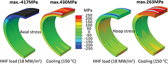
Figure 4. Axial component (left) and hoop component (right) of the thermal stress field produced in the cooling tube after 10 HHF load cycles (heat flux load: 18 MW m−2, coolant temperature of 150 °C) [95]. Adapted from [95], Copyright 2015, with permission from Elsevier.
Download figure:
Standard image High-resolution imageA rigorous cyclic plasticity simulation shows that the plastic straining of the cooling tube occurs only during the fabrication process, provided that the CuCrZr alloy used for the tube does not undergo overaging (ripening of the precipitates) or irradiation creep (dissolution of the precipitates) during subsequent thermal exposure under the HHF loads and neutron irradiation, so that the initial prime-aged microstructure and thus the initial yield strength are preserved. In this case, considerable residual stress can be produced, due to the differential thermal strain mismatch during cooling in the joining process. Concomitantly, overall plastic yield occurs in the tube. The intensity of the residual stress depends on the thermal history—in particular, the effective stress free temperature of the fabrication process.
The presence of strong residual stress can significantly influence the further evolution of thermal stress during the HHF loading, as the secondary stress produced by the HHF loads is superposed onto the residual stress. Assuming a precipitation-hardened state of the CuCrZr tube, the high yield stress of the CuCrZr alloy leads to an accordingly high residual stress (ca. 300–400 MPa), which dominates over the secondary stress of opposite sign.
This feature is well demonstrated in figure 5, where the temporal variation of three principal plastic strains (expressed in a cylindrical coordinate system adapted to the tube geometry) is plotted over the first ten HHF load cycles at 18 MW m−2; (coolant temperature: 150 °C). It is seen that the stress state in the cooling tube already readily enters into the fully elastic shakedown regime upon the onset of the 'first' HHF load, so that no further plastic deformation takes place during the subsequent cyclic HHF loading after the first load cycle [95]. In this circumstance, the risk of plastic fatigue or ratchetting can be excluded. It is reminded that this condition can be met, only if the CuCrZr tube does not undergo softening due to overaging or irradiation creep at a maximum operation temperature. The upper temperature limit to avoid such effect lies between 300 °C–350 °C. The corresponding heat flux load would range from 14 to 18 MW m−2. Should a part of the tube be subjected to still higher temperatures beyond this limit in long-term operation, the CuCrZr tube would possibly undergo a significant plastic fatigue, due to softening by irradiation creep and overaging.
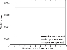
Figure 5. History of the principal plastic strains in the cooling tube during 10 HHF load cycles (heat flux load: 18 MW m−2, coolant temperature of 150 °C) [95]. Adapted from [95], Copyright 2015, with permission from Elsevier.
Download figure:
Standard image High-resolution image4.3.2. Low cycle fatigue of Cu interlayer.
In contrast to the CuCrZr cooling tube, the soft copper interlayer was shown to undergo heavy plastic fatigue (i.e. low cycle fatigue) due to large variation of plastic deformation already existing in the early stage of HHF loading.
This feature is illustrated in figure 6, where the periodic temporal variation of three principal plastic strains (in a cylindrical coordinate system) is plotted. It is found that the radial and axial components exhibit quite large plastic strain amplitudes, whereas the hoop component has a roughly constant magnitude. The fatigue lifetime (the number of cycles to failure due to plastic fatigue) can be estimated using the plastic strain amplitudes on the basis of Manson–Coffin type fatigue life data. For the present ITER-type target model, the design estimates (predicted fatigue lifetime divided by 20) cannot fulfill the ITER load specification. This result indicates that the plastic fatigue of the Cu interlayer may pose a critical design concern in terms of the structural reliability of the whole target PFC.

Figure 6. History of the principal plastic strains in the Cu interlayer during 10 HHF load cycles (heat flux load: 18 MW m−2, coolant temperature of 150 °C) [95]. Adapted from [95], Copyright 2015, with permission from Elsevier.
Download figure:
Standard image High-resolution image4.3.3. Deep cracking of W armor block.
Several recent HHF test campaigns performed on ITER divertor target mock-ups demonstrated that W armor blocks were vulnerable to macroscopic cracking when the applied cyclic HHF loads were raised to 20 MW m−2, which corresponds to the peak heat flux during slow transient events (loss of plasma detachment) [96]. HHF fatigue loads at 20 MW m−2 often produced a deep crack through individual W blocks. The cracks were normally initiated on the top surface being heated, and grew further downward—often even reaching the cooling tube. The mechanism of the deep cracking phenomena was clarified by the authors in a computational study based on fracture mechanics, where the crack initiation was attributed to plastic fatigue, while the subsequent crack growth was shown to be a result of tensile stress concentration at the crack tip [97]. The strong tensile stress field at the crack tip appears during the cooling stage until the crack grows up to ca. 4.5 mm long depth downwards. On the other hand, if the crack becomes larger than 5.5 mm, then the tensile stress field at the crack tip develops during the HHF heating stage. This fracture feature is visually illustrated in figure 7 where the thermal stress fields (horizontal component) in the cross section of the target PFC are plotted for the HHF loading (20 MW m−2) and the cooling (150 °C) phase, respectively. The stress fields are presented for three different sizes of cracks (1.5, 3.5 and 5.5 mm). It is seen that the upper region of the armor is compressed during the HHF loading (crack is closed) while tensile stress states prevail in this region during the cooling (crack is opened). Figure 7 reveals that the stress state and the intensity of the singular stress field at the crack tip varies with the crack depth.
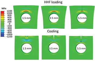
Figure 7. Thermal stress fields (horizontal component) in the cross section of the target PFC plotted for the HHF loading (20 MW m−2) and the cooling (150 °C) phase, respectively. (Crack size: 1.5, 3.5 and 5.5 mm)
Download figure:
Standard image High-resolution imageFigure 8(a) shows the J-integral values at the crack tip computed as a function of crack lengths ranging from 0.5 mm to 5.5 mm from the top surface [97]. J-integral is a direct measure of crack tip loading, indicating the driving force for crack extension. In figure 8(a), the J-integral values at two positions of the crack front (free surface end and symmetry center) are presented for the HHF loading (20 MW m−2) and the cooling (150 °C) case, respectively.

Figure 8. J-integral values of a vertical crack in the W armor during cooling (a) and HHF heating (b) computed as a function of crack lengths [97]. Coolant temperature is 150 °C; and HHF loading is 20 MW m−2. Reprinted from [97], Copyright 2015, with permission from Elsevier.
Download figure:
Standard image High-resolution imageFigure 8(a) shows that the crack tip J-integral values during the cooling stage are sufficiently high compared to the critical fracture energy (or toughness) of the W armor (ca. 0.25 mJ mm−2) in the depth range up to ca. 4.5 mm so that the crack can grow further up to 4.5 mm in the repeated cooling phases, once it has been initiated at the surface. On the other hand, figure 8(b) shows that during the HHF heating phase the J-integral begins to increase rapidly only after the crack size has reached 5.5 mm reaching the critical values.
It is noted that the surface crack is initiated by plastic fatigue. In an extreme HHF loading case (20 MW m−2) as assumed above, significant fatigue may take place in the surface layer since this region is subjected to large plastic strain amplitudes and tensile stress in the initial transient stage of cooling. The fatigue life estimated for the HHF load of 20 MW m−2 is less than 90 load cycles. Such a significant fatigue effect is attributed to the low yield stress of W in the surface layer caused by recrystallization.
4.3.4. Surface cracking of W armor under thermal shock.
W armor will also be exposed to characteristic thermal shock loads during transient instabilities such as edge localized modes (ELMs). The thermal loads caused by ELMs are predicted to be frequent (∼1 Hz), short (∼1 ms) and extremely intense (∼1 GW m−2), releasing huge amounts of thermal power (∼1 MJ) onto the surface. In many HHF fatigue tests simulating ELM-like thermal shocks, characteristic surface cracking features were observed [98, 99]. They showed that a network of many short cracks was created on the W armor surface where the typical crack depth ranged from several tens of μm to a few hundreds of μm.
In computational fracture mechanics studies, the crack patterns observed experimentally could be reproduced by use of J-integral calculation and XFEM simulation [100–102]. The XFEM study showed that the crack formed within the heat-loaded area is short and straight, whereas the crack near the boundary is long, deflecting its path from the vertical to horizontal orientation parallel to the surface. The origin of the driving force of surface cracking was the strong tensile stress field (radial component) which builds up as plastically induced residual stress. This tensile residual stress is a result of the compressive radial plastic strain (1.8%) produced locally within the heat-loaded area during ELM-like thermal shock loading. In contrast, the outer region surrounding the central heat-loaded area is deformed only elastically. When the HHF shock pulse is turned off, the thermal strain in the outer region relaxes elastically, trying to recover its original shape, while the plastic strain in the heat-loaded area remains as permanent deformation. Thus, the elastic recovery of the surrounding region exerts a tensile traction onto the heat-loaded surface area in the radial direction during cooling. The resulting tensile stress is higher than 1000 MPa, which is strong enough to cause crack initiation. This mechanism is illustrated in figure 9, where the profile of the radial component of the plastic strain and radial stress are plotted for three different time points, viz. at the end of the pulse (1 ms), shortly after the pulse shut-off (2 ms), and after cooling (10 s) [100, 101].
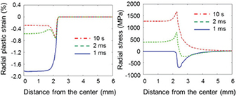
Figure 9. Radial profile of the radial component of the plastic strain and radial stress plotted for three different time points (at the end of the HHF pulse: 1 ms, shortly after pulse shut-off: 2 ms, after complete cooling: 10 s) [100, 101]. Adapted from [100] and [101], Copyright 2015, with permission from Elsevier.
Download figure:
Standard image High-resolution image4.4. Summary and conclusions
The key drivers for divertor target development for a DEMO reactor are the requirements of sufficient power exhaustion capability and solid structural reliability. A successful target design should be able to assure these essential requirements for long-term operation (say, two full power years) and neutron irradiation accepting the transient thermal loads due to ELMs and reattachment. Given that the conventional ITER-type divertor target has been shown to fulfill the ITER specifications, the ITER concept is also regarded as a reasonable baseline design for the DEMO divertor, at least for starting phase. In order to make a design extrapolation from the ITER loading conditions to those of a DEMO, understanding of loading nature and failure features are indispensable. Some of the hitherto reported computational studies could deliver reasonable explanations on the prominent failure features observed in the previous HHF tests of ITER divertor target mock-ups. Deep cracking of W armor blocks (slow transients), surface cracking of W armor (ELMs) and plastic fatigue of soft Cu interlayer (pulsed operation) were identified as primary failure modes. Plastic fatigue of CuCrZr tube did not exhibit any fatigue risk, in the absence of irradiation creep or overaging.
5. Inherent passive safety in a loss-of-coolant (LOCA) event
Safety and environmental aspects of fusion power are considered in a series of fusion power concepts developed in the framework of the European Fusion Programme [103]. Moreover, according to the European Roadmap towards a DEMO the 'safety and environmental sustainability' of a Fusion Power Plant (FPP) has been formulated as the top level requirement to be accomplished by a credible power plant design 14 . The term safety demands the implementation of a safety assessment for a generic plant design, and has to cover the following two major aspects:
- determination of the maximum releasable inventories and quantities, and the
- analysis of all conceivable incidents and accident scenarios with respect to their consequences.
The determination of the maximum releasable inventories called 'source terms' necessitates an assessment of all radioactive sources, easily mobilised fractions (gas, dust) as well as the plant internal energy causing or even aggravating the release. Most of the high energy sources are located near or in cryostat domain of the reactor hall (see figure 10, bottom left). Preliminary assessments conducted for a DEMO like configuration have identified different sources present in operation but also after plasma shut down. Energy sources are identified such as enthalpy stored in structure and coolant, plasma thermal energy, magnetic energy in coil systems, disruption mechanical energy caused by a plasma collapse in operation; decay heat after a plasma shutdown; energy arising from exothermal chemical reactions between materials, and energy released due to a postulated H2 explosion [104].
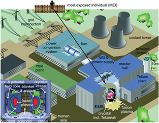
Figure 10. Schematic plant layout of a DEMO fusion power plant. Bottom left: energy sources located in the cryostat vessel.
Download figure:
Standard image High-resolution imageAll those energies stored or circulating in the power plant system could lead in the case of an anticipated internal or external event to a degradation of static and dynamic barriers confining radioactive materials within the plant. The aim of a safe plant design is to prevent any off-site emergency measures for the most exposed individual (MEI) outside the plant at any incident conceivable, see figure 10. Regarding the radioactive sources the following contributors have been identified for DEMO [104]:
- tritium inventory in different facility regions (within the vacuum vessel (VV), in primary heat transfer systems (PHTS), in fuel cycles etc);
- dust in the VV: particles, concretionary drop and flakes. Particles (mainly tungsten and EUROFER) come from plasma-wall interaction in normal operation, as well as in other status (e.g. disruption);
- activated corrosion products (ACPs) in PHTSs caused by corrosion, erosion (e.g. in water-cooled blanket/divertor, in LiPb breeder box);
- neutron sputtering products (e.g. in gas cooled blanket);
- activated materials, e.g. in breeding material; in PFC (plasma-facing components) and in-vessel structure (VV) as well as in coolant (e.g. activation in water or liquid metals);
- possible radioactive isotopes from noble gases used for plasma seeding (injecting controlled quantities of gaseous impurities mainly with neon or argon), which may be generated by neutron capture processes, in particular neon, argon, krypton, xenon. They can easily be mobilised and should be quantified, and their radioactive consequences should be evaluated;
- nitrogen seeding for ELM (edge localized mode) mitigation, nitrogen impurity in structure, injected nitrogen to avoid H2 explosion.
From the FFMEA (functional failure modes and effects analysis) analyses for the systems of a FPP a set of postulated initiating events (PIEs) can be identified, which can be considered to envelope a series of events in the sense that they yield the maximum radiological consequences. In case of a DEMO, regarding the identified PIEs from the FFMEA for the blanket the representative accident initiators are the in-vessel LOCA (loss-of-coolant accident), the ex-vessel LOCA, the in-box LOCA, the LOFA (loss-of-flow accident), the LOHS (loss-of-heat sink), and a loss of power.
With respect to the PFCs, an in-vessel LOCA accident affecting the blanket represents the most challenging issue, which will be discussed subsequently.
5.1. Safety aspects
The term in-vessel LOCA means the failure of cooling channels in the plasma-facing first wall (FW), which in turn yields a coolant ingress into the VV (see figure 11).

Figure 11. Scheme of different loss-of-coolant accidents (LOCAs) considered for a safety evaluation.
Download figure:
Standard image High-resolution image5.1.1. Identification of causes.
First wall failure can be caused by thermal and/or mechanical stresses triggered e.g. by a plasma disruption, a temperature increase in the structure, or a pressurization of the coolant channels.
In case of a plasma disruption, eddy currents are induced, circulating through the mechanical structures and generating large electro-magnetic forces, as well as thermal loads (arising from ohmic heating), which in turn drive damage to the first wall.
In case of an ex-vessel LOCA, a double guillotine break in a large pipe is assumed leading to a coolant spill out (if no redundancy is foreseen) and air ingresses into the loop (see figure 11). In this context the grace time for the intervention of the fast plasma shutdown system (FPSS) has to be evaluated in such a manner that the integrity of the first wall structures is assured well before critical material conditions are reached [105]. In this context, the strength reduction by the structural temperature rise and melting point of the material are essential parameters describing the first wall integrity. If the integrity fails, in-vessel LOCA occurs as an aggravating failure. This multiple failure event is categorized as a design extension condition (DEC) according to [106].
In case of a LOFA caused by several means such as circulator seizure, malfunction of valves, clogging in first wall-breeding blanket (FW-BB) channels or piping or instrumentation & control failure, the first wall temperature and also pressure of cooling channels will rise without the FPSS. The pressure should be released to the pressure control system (PCS). Otherwise, if the pressurization exceeds the design limit, it will mechanically affect the FW-BB integrity considerably before reaching the critical temperature. If FW-BB integrity fails, the in-vessel LOCA also progresses as an aggravating failure, which subsequently triggers other failures. A failure of the PCS, spurious opening of relief valves, relief device internal leak or instrumentation & control erratic In/Out signal, LOHS and in-box LOCA (see figure 11) may also end up in an in-vessel LOCA, if the FPSS is not activated. Additionally, a large rupture and a leak of the sealing weld in the first wall are two representative PIEs for an in-vessel LOCA [105].
Figure 12 illustrates schematically the temporal evolution of an in-vessel LOCA. It occurs during normal operation at typical state variables as q0, p0, T0 and full nuclear power. Considering a response time of pressure sensor for a pressure measurement, the LOCA can likely be detected at tr
(e.g. tr
= 2.0 s in the HELOKA-HP facility [107]). The activation of the FPSS takes a time of  (e.g.
(e.g.  s in ITER) to terminate the plasma. In the shutdown state during a time tf
the decay heat still heats the structures, although it is less than ∼2% of the nuclear power in normal operation. The FPSS itself causes plasma disruption producing a peak surface heat load of qmax within a disruption time of
s in ITER) to terminate the plasma. In the shutdown state during a time tf
the decay heat still heats the structures, although it is less than ∼2% of the nuclear power in normal operation. The FPSS itself causes plasma disruption producing a peak surface heat load of qmax within a disruption time of  (e.g.
(e.g.  s in ITER). The decay heat rapidly declines immediately after the plasma shut-down, but it continues to feed thermal power into the vacuum vessel for seconds, minutes, hours, days or even longer, depending on the material composition, which is calculated through a neutronic analysis. Depending on the first wall break size the coolant pressure drops and the coolant ingresses into the VV. If the pressure limit of the VV is reached, it will be discharged to an expansion volume (EV, for gas) or to a VV pressure suppression system (VVPSS, for liquid). If the LOCA is not detected and the plasma burns continuously further, the first wall temperature can increase up to the melting point, which is reached in the time at tm
. The mitigation with the FPSS stops the temperature rise and the first wall integrity can be assured.
s in ITER). The decay heat rapidly declines immediately after the plasma shut-down, but it continues to feed thermal power into the vacuum vessel for seconds, minutes, hours, days or even longer, depending on the material composition, which is calculated through a neutronic analysis. Depending on the first wall break size the coolant pressure drops and the coolant ingresses into the VV. If the pressure limit of the VV is reached, it will be discharged to an expansion volume (EV, for gas) or to a VV pressure suppression system (VVPSS, for liquid). If the LOCA is not detected and the plasma burns continuously further, the first wall temperature can increase up to the melting point, which is reached in the time at tm
. The mitigation with the FPSS stops the temperature rise and the first wall integrity can be assured.
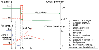
Figure 12. Scheme of parameter evolution in an in-vessel loss-of-coolant accident (LOCA).
Download figure:
Standard image High-resolution image5.1.2. Selected accident sequences.
LOCA analyses have been conducted in several FPP concept studies since the safety and environmental assessment of fusion power have been recognized being a vital part for the public acceptance of fusion power. Herein, the SEAFP program in 1990 [103] can be considered as the first addressing the analysis of accident sequences with respect to safety aspects. From the analysis results an evaluation of accident consequence with respect to dose rate and its influence on the public can be conducted.
Since DEMO is still in pre-conceptual design phase, and safety analyses based on its four blanket concepts are on-going, up to now only accident sequence analyses are available, which correspond mainly to those already reported in the power plant conceptual study (PPCS) [108] and essentially covers mainly the blanket aspects, since the blanket covers more than 80% of the plasma confining area. Nevertheless, the PPCS study provides the most representative sequence evolutions, results and consequences, and can be still adopted as reference.
Within the PPCS study five different blanket model concepts have been investigated (see [108] and [109]). The breeding blanket concepts called model A (water cooled lead lithium—WCLL), B (helium cooled pebble bed—HCPB), AB (helium cooled lead lithium—HCLL) and C (dual coolant lead lithium—DCLL) are involved in the current DEMO development as well. Within the PPCS for the divertor in models B, AB and C helium has been considered as coolant, while in the current European DEMO approach water is favoured irrespective of the blanket concept. A comparison of all events studied for the five models in the view of the maximum attainable radiologic dose showed that a LOFA inducing subsequently an in-vessel LOCA in model B (HCPB) leads to the highest dose value among all LOCAs.
The postulated initiator of the event is an assumed pump trip in one of the FW-BB heat transport systems, leading to a loss of flow in one of the cooling loops, without a pump coast-down. Additionally, it is assumed that the FPSS does not intervene. As a consequence, the surface temperature of the PFCs increases continually until the critical temperature of the plasma-facing first wall component (EUROFER at 1073 K) is reached, and a break in the in-vessel FW-BB cooling channels happens. When the helium enters the VV, a plasma disruption occurs, transferring an energy of 6.0 MJm−2 onto 418.0 m2 of the first wall in 1 s. The FW-BB of the failed loop is first cooled down with residual coolant present before the complete drainage. The helium ingress into the VV causes a pressure rise up to a level of 1 bar; beyond this value the rupture disc fails and releases the gas towards the EV. The EV has a tentative free volume of  m3 (initial conditions of the air internal atmosphere are 30.0 °C and 0.09 MPa). During the entire leak period 2000 kg of helium (92% of the primary inventory) are discharged through the break into the whole containment. Finally, the overpressure in the VV should be safely mitigated under the design pressure of 0.2 MPa.
Leakages from the VV and EV building towards the external environment have to be considered. Radioactive materials inventories and their mobilization for model B are: tritium in the VV of 1 kg, dust of 10 kg with 7.6 kg stainless steel dust and 2.4 kg tungsten dust, and tritium in coolant of 1 g per loop.
Concerning the releases to the outside environment for this sequence, large amounts of the initial inventories are dispersed 24 h after the beginning of the accident. The major source is the high daily leakage (75%) of the EV. A reduction of the EV leakage rate from 75% of the volume per day down to 1% would be more effective than using a detritiation system (DS). As matter of fact, the adoption of the DS in addition to a decrease of the EV leakage rate to 1% vol./day reduces the tritium release further by 55%, and also the dust release by 30%.
It is important to assess the consequences to the public in terms of doses of other potential consequences. For the German regulation the dose criterion is defined as committed effective dose equivalent for the first seven days of exposure. For this LOFA accident, the dose value for the seven-day dose to MEI at 1000 m distance (24 h release, 95% fractile) was calculated to be 0.42 mSv. This dose value is far below the dose criterion for evacuation of 50 mSv, which is recommended by the International Commission on Radiological Protection (ICRP-60) and also used in many national regulations and for ITER. The maximum radiological dose to the public arising from the most severe conceivable accident driven by in-plant energies (bounding temperature sequence) was 18.1 mSv for the PPCS model B. It has to be stated that this value is obtained for a rather hypothetical event sequence assuming a total loss of cooling from all loops in the plant. Additionally, no active cooling, no operational functionality of active safety systems is anticipated, and further no human intervention whatever is considered for a prolonged period. The only assumed rejection of decay heat is by heat conduction and radiation through the layers and across the gaps of the model, towards the outer ambient, where likely a heat sink is provided by convective circulation of the building atmosphere.
5.2. PFC in contact with coolant from the in-vessel LOCA
For the water cooling concept, in case of LOCA, large quantities of H2 can be generated through chemical reactions of water/steam with the various metallic materials used, particularly at high temperatures. Consequences could arise from mixing the H2 for example with O2 and lead to a large-scale propagation associated with a subsequent explosion or fire. Adopting He as coolant not only for the BB but also for the divertor does not exhibit any H2 production in the VV. In concepts like the WCLL, HCLL or DCLL using PbLi as breeding material or coolant, its loop failure may lead to a H2 production either due to a contact with the water coolant or steam or due to humidity, but not with the PFC.
Tungsten is considered as the PFC for the PPCS models and also assumed defined as prime PFC material for both the first wall and divertor in the DEMO baseline. An exothermal W-air reaction can occur e.g. by an ex-vessel LOCA inducing an in-vessel LOCA leading to an air ingress into the VV through the pipe break and leakage. The energy released is substantial according to equation (1):

The generated  is highly volatile and radioactive. It could be released into the environment via the LOCA as bypass. W-air reaction rates (RR) at a pressure of 85 kPa are given in [110] and read to:


Exothermic W-steam reaction can occur by an in-vessel LOCA, in which either water or air/humidity ingresses into the VV (ex-vessel LOCA inducing in-vessel LOCA). The corresponding reaction is:

The W-steam reaction rate at a steam pressure of 85 kPa shows the following relation [110]:

Using a system code such as MELCOR (adapted to fusion), in which chemical reactions and reaction rates for W, energy release and H2 production are implemented, the risk potential can be estimated with respect to the PFC inventory or vice versa maximum allowable water/steam ingress conditions caused by an in-vessel LOCA.
W represents the main source of dust in the VV. Activated dust results from the erosion of the PFC by plasma radiation during regular operation and from its evaporation during plasma disruption events. Dust so produced may be copious, radioactive, chemically reactive, and/or chemically toxic. Posing significant safety hazards, dust is mobilized in an off-normal event and adversely affects the overall system. In DEMO, with W dust from PFCs for the blanket and divertor, the greatest concern is its radio-toxicity, because of the high activation of W caused by neutron irradiation, especially at the end of an operational cycle.
Dust is chemically reactive if combustible gas is generated during interaction with coolants or air ingress, e.g. by a leak in the VV. Dust generation mechanisms in tokamaks lead to rather small particle sizes, exhibiting a large surface area. High temperatures associated with some postulated accidents in water-cooled systems can cause a significant H2 generation rate leading in turn to explosive concentration level. The relative generation rate of H2 versus temperature for W dust reacting with steam is well known. Another chemical reactivity concern is posed by rapid dust oxidation upon exposure to air.
The W dust quantity on the hot surfaces of the divertor has to be limited in order minimize the H2 production in the VV. The design of a FPP must therefore limit the number of off-normal events to maintain dust inventories at reasonable levels, and/or develop in situ techniques to remove the dust. The dust may present operational difficulties in a FPP, due to its capability of tritium retention.
5.3. Mitigation of the release of W oxidation
The use of smart self-passivating W alloys as PFC can be advantageous from the safety point of view. Such smart alloys represent an attractive option for protection of PFC against the release of radioactive W oxide [111]. The study of new yttrium-containing W–Cr–Y alloys shows an excellent self-passivation behavior. It reduces the oxidation rates by one order of magnitude compared to the W–Cr system [112]. The requirements for the alloys can be formulated to:
- low neutron activation
- low volume increase by oxidation
- good adhesion of the oxide to the alloy
- high melting point of alloys and oxides
- limited sputtering erosion
- good thermal properties (especially high heat conductivity)
- favourable mechanical behaviour such as high DBTT (ductile-to-brittle transition temperature) and high fracture toughness
- low tritium retention and diffusion of H2.
However, the development of these materials is still at the beginning, a detailed report is presented in section 10. Prototype components need to be tested in high heat flux performance, to further study and evaluate the prospects and limitations of these materials in view of the safety requirements.
6. Tritium permeation
The development and application of sufficient tritium permeation barriers (TPB) is crucial in order to guarantee the environmentally and economically acceptable operation of a D–T fusion power plant. Along with tritium permeation reduction, the barriers have to fulfill various other physical and mechanical properties according to their application, e.g. high heat stability and neutron irradiation resistance in the first wall, and lithium–lead compatibility in the breeding unit.
The disadvantage of the use of tritium is its radioactivity, with a half-life time of approximately 12 years. The high permeation of hydrogen through most metals at elevated temperatures necessitates special precautions in order to ensure safe reactor operation. Furthermore, the loss of fuel during operation has to be prevented, for a predictable and economical fuel cycle.
The two main sources of tritium in the reactor are the plasma itself and tritium from lithium–neutron nuclear reactions in the breeding blanket units. The demonstration power plant, DEMO, will be the first fusion reactor to be equipped with full breeding blanket units. A tritium loss of several kg per year is expected, if no TPB is applied [113]. This loss of tritium is ecologically and economically unacceptable; therefore, it is essential for DEMO to develop and apply sufficient TPBs. Depending on the reactor concept and materials used, TPBs with a permeation reduction factor of about 100 are required [114, 115].
There are various proposals for the design of the breeding blanket, e.g. using a liquid lithium–lead alloy or a solid breeder blanket. In the liquid lithium–lead alloy, the lithium–lead circulates between the breeding blanket and the tritium extraction system. Tritium will be present in the lithium–lead pipes. In the solid breeder blanket, lithium ceramics or lithium–lead and beryllium pellets will be surrounded by a gas flow, which transport the tritium to the extractor system. Therefore, as in the lithium–lead alloy, the transport pipes will contain tritium.
The main components where tritium permeation has to be considered are the following: the plasma facing components and parts which are reachable by tritium from the plasma; the breeding blanket and the transport pipes between the breeding blanket and the tritium extraction system; the structural materials between the pipes and the cooling system; and the steam generator circuit.
Plasma facing components: two different first wall materials are suggested for the DEMO reactor: tungsten and low activation steel, e.g. EUROFER97. Tungsten has a low tritium solubility. Therefore, compared to other components, the tritium absorption will be low. Nevertheless, the diffusion of hydrogen through tungsten is not negligible, and the solubility can be increased due to ion and radiation induced defects [116]. For protection of the structural materials behind the tungsten layer, a permeation barrier between the plasma facing components and the structural materials would be applied. Otherwise, the structural material will sponge up the tritium, which will then diffuse through the tungsten layer, because of the higher tritium solubility in steels compared to that in tungsten. If EUROFER97 is to be used as a plasma facing component, the permeation barrier has to be applied as close to the surface as possible, due to the high tritium solubility and diffusivity.
Structural materials: a reduced activation ferrite/martensitic steel, e.g. EUROFER97, is foreseen as the structural material in DEMO. The tritium permeation through martensitic steels is several orders of magnitude higher than that through tungsten [117]. Therefore, it is important to apply TPBs. This protection is especially important at the vacuum vessel and between the breeding unit, the tritium transport pipes, and the cooling unit.
Breeding blanket and tritium transfer system: Due to the low solubility of tritium in lithium–lead [118], TPBs with very low tritium solubility have to be applied in the liquid lithium–lead alloy. In addition to the protection of the pipes, it is important for the tritium extraction that the tritium remains in the transfer system. A further challenge at this point is the compatibility of the barrier material with lithium–lead. In the solid breeder blanket the same holds as for the liquid lithium–lead alloy. The compatibility of the permeation barrier with lithium ceramics, lithium, lead and beryllium has to be confirmed.
Steam generator circuit: due to the connection to the environment, a safety barrier has to be applied for the case that tritium reaches the cooling unit. This is the last chance to ensure a safe and environmentally friendly reactor operation via a TPB.
A few approaches to the control of tritium permeation through fusion reactor components are possible. A simple and fundamental way is to construct each component with a tritium-impermeable material; however, it seems a long shot that any material can satisfy engineering requirements to follow all the design guidelines. One of the most practical solutions is to coat a thin film or to form an integrated layer structure to suppress tritium permeation without change in the basic properties of the structural materials. To apply to each component, the layer should be thin enough not to block the heat transfer: the heat load from the fusion plasma must be mitigated at the first-facing components; the thermal energy must be transferred at the breeding blanket, and extracted at the heat exchanger. Another concept, especially in the breeding blanket, is to construct a double-wall system. Of course, however, the blanket design should be drastically rearranged in this case.
While similar properties of the TPB will be required at the plasma-facing components in different types of fusion reactors, the requirements at the breeding blankets vary depending on blanket concepts. In the breeding blanket, tritium generated from solid breeders (Li2TiO3, LiSiO4) is purged with He with H2, while liquid breeders (Li, Li–Pb, Flibe) transport tritium by themselves to the tritium recovery system. Regarding Li, the tritium leakage into cooling media will be negligibly small, due to its high tritium solubility [119]. This means that, conversely, tritium recovery from Li is relatively difficult. On the other hand, Li–Pb and Flibe have much lower solubility than Li, which means tritium permeation through structural materials is more serious. In addition, corrosion and erosion of the structural materials must be strictly controlled to avoid degradation of mechanical properties, and an obstruction of the flow by precipitates formed at the low temperature region. In the heat exchanger system, the temperature is lower than that of the blankets; however, thin tubes to ensure the high heat-exchange efficiency will increase tritium permeation. Eventually, the tritium permeation to the environment should be controlled in terms of safety.
In section 11, permeation barrier development over several decades will be condensed, and remaining issues on this matter demonstrate the current status and further challenges.
Material concepts and development lines
7. Fiber-reinforced composite materials
7.1. Strengthening: fibre-reinforced copper composites
Priority requirements for heat sink materials that are used for the design of highly loaded PFCs are a high thermal conductivity as well as sufficient mechanical properties regarding the envisaged operating conditions. Precipitation hardened Cu alloy CuCrZr is currently regarded as the most appropriate heat sink material for highly loaded PFCs in magnetic confinement fusion devices [120–123]. Moreover, CuCrZr is also regarded as the baseline heat sink material for a water-cooled divertor in a DEMO reactor. CuCrZr offers a combination of properties suitable for HHF application in PFCs [124].
However, it has been pointed out that there are high-impact designs engineering risks regarding the use of copper alloys, particularly CuCrZr, in a DEMO reactor [6, 125]. The most serious issues concerning CuCrZr relate on the one hand to the pronounced loss of ductility under neutron irradiation at temperatures lower than 453 K [6]. On the other hand, CuCrZr is susceptible, due to its hardening mechanism, to overaging and recrystallisation at elevated temperatures [66]. That is the reason why a maximum service temperature of 573 K has been recommended for CuCrZr with regard to DEMO applications [12]. These limitations impose a strong constraint on the design of corresponding PFCs.
Cu-based fibre-reinforced composite materials which exhibit a high thermal conductivity as well as enhanced higher-temperature strength could be a viable and superior alternative in this respect. In the following, only a brief overview on two promising material concepts is given. A recent comprehensive review on this topic is available in [126].
One example of a Cu matrix composite material is silicon carbide fibre-reinforced Cu (SiCf/Cu), which has been investigated for heat sink applications in highly loaded PFCs for many years [127–133]. Mechanical characterisation results confirm the strong reinforcing effect of SiC fibres even for rather low fibre volume fractions, and indicate a high manufacturing quality of the tested composites. Although the thermal conductivity of SiC fibres can be rather low, it has been demonstrated that unidirectionally reinforced SiCf/Cu composites preserve an acceptably high transversal thermal conductivity [131]. The overall performance of SiCf/Cu composites has been evaluated by means of HHF fatigue tests with demonstrator mock-ups [132].
Another class of Cu-based fibre-reinforced composite materials is W fibre-reinforced Cu (Wf/Cu). The material system W–Cu is on the one hand characterised by distinctive differences in the properties of the individual metals, and on the other hand by no mutual solubility and a very good wettability of W with Cu melt, which allows straightforward fabrication of these two materials into metal-matrix composites (MMCs) by liquid Cu infiltration. Wf/Cu has been studied extensively by the NASA Lewis Research Center from the 1950s on [134–137]. Wf/Cu composites have the potential to be used as a high thermal conductivity, high strength composite material suitable for HHF applications. This potential has been evaluated by means of HHF tests performed at the hydrogen beam irradiation facility GLADIS at IPP Garching [138].
7.2. Toughening: tungsten fibre-reinforced tungsten composites
Despite the outstanding properties of tungsten as plasma-facing material, e.g. its good erosion resistance and low tritium retention, its brittleness at low temperature and its susceptibility to embrittlement during operation are a major concern for the use of W in plasma-facing components [139].
As described above, there are huge efforts to improve the toughness of tungsten e.g. by alloying or microstructural modification. Whereas alloying is not very promising, microstructural fining is an adequate method to increase the toughness e.g. in wire or foils. Here, major manufacturing problems are the extension to larger volumes (bulk material) and/or a very high complexity (e.g. severe plastic deformation). A good overview is given by [21] and [20]. A remaining problem for all toughening efforts so far is the susceptibility to re-embrittlement, either by the loss of the preferred microstructure [140] and/or by irradiation [141, 142].
For ceramics which feature similar brittleness restrictions the application of composite concepts provides an adequate method to increase the toughness [143]. A good example is silicon carbide reinforced with silicon carbide fibres (SiCf/SiC) with a fracture toughness of e.g. 25 MPa m0.5 [144] compared to a fracture toughness of only 2–4 MPa m0.5 [145] for pure SiC. The resulting good thermal shock resistance is one reason for the choice of SiCf/SiC as a candidate structural material for the blanket in a future fusion reactor [146].
A similar reinforcement method has been suggested to increase the toughness of tungsten [147]. Tungsten fibres, made of drawn tungsten wire, are coated by an engineered interface and embedded into a tungsten matrix. The composite is known as tungsten fibre-reinforced tungsten Wf/W. Basic work has been reported in [148] for interfaces and in [149] for the synthesis and characterization. Tungsten wire has been used before in composites together with a matrix of copper (see section 7.1), superalloys [150] and even with plasma sprayed tungsten [151]. In these materials the main objective of the W wire reinforcement has been the increase of strength rather than the increase of toughness.
In the following, we summarize the theory of this toughening mechanism, as well as studies on the composite constituents: fibre and interface. Possible fabrication processes are shown and the results of mechanical tests are presented.
7.2.1. Theory.
Starting with Aveston et al [152], toughening in brittle matrix composites has been extensively studied for many years (see for example [143, 153, 154]). Having brittle tungsten as a matrix material, the behavior of Wf/W composites follow the same rules, and has been described based on this work [155–157].
Brittle materials do not possess the possibility for stress redistribution. This means if the local stress exceeds the local strength, e.g. at a crack tip, the whole system fails. Toughening by fibre-reinforcement works through the introduction of mechanisms for energy dissipation. This allows the relaxation of stress peaks, and thus increases the resistance against crack growth and therefore the toughness. As these mechanisms are not an intrinsic property of the material, but provided externally, they are also known as extrinsic toughening. If there is no possibility to improve the crack growing resistance of a material itself, this is the only way to improve the toughness of brittle materials [158, 159].
The contribution of these mechanisms  to the toughness acts behind the crack tip, and thus lowers (by dissipation) the crack driving energy G, rather than directly influencing the matrix material at the crack tip. The following equation describes this relation:

| with | |
| G | : energy release rate for crack driving |

| : consumed energy by extrinsic mechanisms |

| : critical energy release rate of matrix |
Many different mechanisms have been reported, e.g. toughening by reinforcements like whiskers or fibres or microstructural mechanisms like transformation or matrix micro-cracking [143]. In this context, toughening by fibres is reported as the most effective mechanism (see table 2).
Table 2. Extrinsic toughening in ceramics after [143].
| Mechanism | Highest toughness in (MPa m0.5) |
|---|---|
| Transformation | ∼20 |
| Microcracking | ∼10 |
| Metal dispersion | ∼25 |
| Whiskers/platelets | ∼15 |
| Fibres | ⩽30 |
If a crack bypasses such fibres, they cause a traction force t on the crack faces, hindering further growth of the crack. The contribution to the toughening  can therefore be determined according to equation (6) by integrating the contributions of all fibres
15
.
can therefore be determined according to equation (6) by integrating the contributions of all fibres
15
.
| with Vf | : volume fraction of fibres | (—) |

| : specific energy consumption | (J m−2) |
| umax | : maximum crack opening | (m) |
| t(u) | : traction of reinforcements on crack faces | (MPa) |
An example of this behavior are ceramic fibre reinforced ceramics, which show a superior fracture toughness compared to the bulk ceramics, although their constituents are fully brittle [31, 144]. As a consequence, toughening is maintained even if the intrinsic properties of the material become degraded. In the case of Wf/W this was shown for model systems [155] and for bulk material [160]. There, the fracture toughness could be significantly improved by mechanisms not relying on any bulk material plasticity.
7.2.2. Composite characteristics.
Fibre.
The tungsten fibres used in Wf/W are made of commercial drawn tungsten wire, which is characterized by high tensile strength, remarkable flexibility and notable ductility. This is attributed to a unique microstructure of elongated fine grains caused by the drawing process during fabrication. In figure 13, typical stress-strain curves obtained in tension tests of as-fabricated and annealed W wire doped with several 10 ppm potassium (K) are shown [161]. K doped W wires show ductile behavior up to an annealing temperature of 2173 K (30 min). The tensile strength stays up to about 2000 MPa for this temperature. At an annealing temperature of 2500 K (30 min) secondary grain growth leads to embrittlement. Such K doped wire has a long tradition in the illumination industry [162]. During the drawing process, K forms small bubbles which are aligned along the grain boundaries and pinning these, leading to superior temperature stability (more details in [163]). Tensile tests have also been used to investigate the mechanical properties of pure tungsten wire [164]. In the as-fabricated case and after annealing at 1273 K (3 h), pure W wire shows ductile behavior and a strength of 2900 MPa and  MPa respectively. A heat treatment of 1900 K (30 min) leads to embrittlement, and a mean strength of approximately
  MPa.
MPa.
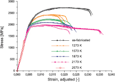
Figure 13. Typical stress–strain curves of tensile tests of potassium doped tungsten wire at different annealing stages [161]. © The Royal Swedish Academy of Sciences. Reproduced by permission of IOP Publishing. All rights reserved.
Download figure:
Standard image High-resolution imageBesides this, a key benefit is the ductility combined with a large local plasticity. The plastic deformation of the wire was identified as an important contribution to the toughening in the as-fabricated state of Wf/W [155]. A length of 250 μm was determined as region of increased plastic deformation in single fibre tension tests [165]. Furthermore, W fibres exhibit due to their metallic nature a rather high thermal conductivity (thermal conductivity of pure W: 173 W m−1 K−1 at 293 K, 147 W m−1 K−1 at 573 K [124]) in comparison with other high-performance fibrous reinforcements, such as SiC fibres. The toughness and flexural flexibility of W fibres furthermore enables rather easy handling, and allows that W fibres can be processed by textile technologies in order to produce fibrous preforms [156, 166]. All the above mentioned beneficial properties make W fibres, from the outset, a rather attractive fibrous reinforcement for Wf/W or composite materials in general.
Interface.
The interface between fibre and matrix in Wf/W composites has several functions. It has to provide a physical barrier between fibre and matrix, and thus maintains the composite structure during fabrication and operation. In addition, the interface must provide the load transfer between fibre and matrix and should in this sense be as strong as possible. On the other hand, it is essential that the interface, rather than the fibre, fails during crack propagation, to allow for the toughening mechanisms becoming active [167]. This phenomenon can be quantified by the so-called debonding criterion. For Wf/W where fibre and matrix feature the same elastic properties, the following equation is valid:
with

| : fracture toughness interface | (J m−2) |

| : fracture toughness fibre | (J m−2) |
The interface system in Wf/W has been studied by means of push-out tests for various interfaces [148, 168, 169] and at different annealing stages [170]. As a first step, several interfaces were chosen according to interface types described for fibre-reinforced ceramics (see [171]). Fibre push-out tests were used on model systems consisting of a single fibre embedded into a tungsten matrix, so-called single fibre composites (see figure 14), to evaluate the applicability for Wf/W and to study the microscopic failure mechanisms. The interfaces were deposited on tungsten fibres using magnetron sputter deposition, and were afterwards coated with tungsten by means of chemical vapour deposition. Oxide coatings, i.e.  and
and  , with different thicknesses and multilayer coatings (with W or Zr), as well as pure Er, Cu and C were used.
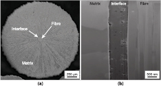
Figure 14. Metallographic cross section of a model system, a so-called single fibre composite sample, consisting of a single fibre embedded in a tungsten matrix. In (a) the cross section of the whole sample is shown. (b) shows a longitudinal section indicating the interface between fibre and matrix in detail. Reprinted from [155], Copyright 2013, with permission from Elsevier.
Download figure:
Standard image High-resolution imageThe interfacial parameters were evaluated by means of fitting the measured data to theoretical equations. This was combined with an extensive microscopic analysis. All interface systems were identified to fulfil the debonding criterion, since all determined values are smaller than  . This is more than five times smaller than the theoretically optimal value and leaves therefore room for optimization.
Composite synthesis.
As shown above, the properties and functionality of the fibres and the interface system determine those of the Wf/W composite system. Therefore, it is important to maintain these during the synthesis process. For the synthesis, typically a fibrous preform is formed as a first step. This can be done by a winding [166] or a weaving process [156]. The interface system is either applied before this process or on the final preform. Afterwards the matrix is deposited on this preform to form Wf/W composites.
The very high melting point and high temperature strength of tungsten makes the application of classical composite production routes like liquid infiltration (more examples in [28]) difficult. The preferred manufacturing technique for tungsten is a powder metallurgical route (70–80% of total production) [13, 22]. During these processes usually high pressure and temperature are applied. The typical pressure range is 200–400 MPa and the typical temperature range is 2273–3273 K. Such conditions have a huge impact on the fibre properties (e.g. due to microstructural changes) and interface integrity (e.g. by thermal decomposition).
Jasper et al [172, 173] started investigations on the applicability of powder metallurgy for the production of Wf/W with respect to the effect on the fibres and the interface system. Hot isostatic pressing was used to produce model systems of single fibres embedded into a tungsten matrix. Besides the microstructural analysis they performed push-out tests to investigate the interface performance. First samples have been successfully produced at various temperature between 1900 K and 2200 K and a pressure of 200 MPa. It was shown that an erbia interface can withstand these conditions, but that its structure is strongly influenced. The pure tungsten wire used in the tests is fully recrystallised during the process.
An alternative processing route for tungsten is chemical deposition from the vapor phase, which is readily used for the production of coatings [174]. In this new composite production route technique tungsten hexafluoride ( ) is reduced by hydrogen (H2) in a heterogeneous surface reaction, to produce solid tungsten. The process is conducted at a temperature between 573 K and 1073 K. In the case of
  typical temperatures are between 673 K and 873 K [148, 149]. The tungsten deposit is formed according to the following reaction:

The main advantages of this process are the comparably low temperature and the force-free character which allows preservation of the interface and fibre integrity, as well as fibre topology.
Surface deposition processes (chemical vapor deposition—CVD) have been used to produce cylindrical model systems containing a single fibre and with a final diameter up to 2.5 mm (see for example figure 14 or [170]). This easy-to-process model system was used to study fibre–matrix interaction, and has also been used in interface studies (compare section 7.2.2). Riesch et al [149, 166, 175] combined the chemical process with an infiltration step, and successfully fabricated bulk Wf/W for the first time. In a dual step process, gas flow and temperature are varied in such a way that material with very low residual porosity (<5%) is produced. The distance between the fibres is approximately 100 μm, leading to a fibre-volume fraction of about 0.3. In figure 15 a cross section of such a material is shown.
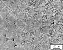
Figure 15. Metallographic cross sections of Wf/W composite produced by the chemical deposition of tungsten hexafluoride on a fibrous preform of tungsten wire [176]. Adapted with permission from [176].
Download figure:
Standard image High-resolution imageRecently, a stepwise deposition of single tungsten wire layers has been established, to produce larger samples [156]. Here, the final sample is built of ten fibre planes, which are grown together step by step. The final sample has a volume of  mm3 and a porosity of 4–7%. The fibre distance is 100 μm within the layers and about 150 μm between the layers, resulting in a fibre-volume fraction of about 0.2.
In summary, CVD processes have the advantage of low production temperature and the absence of mechanical impact, and are therefore ideal for Wf/W production. However, the experience in tungsten bulk production is low. For example, it is unknown whether it will be possible to influence the microstructure or the composition in a desired way. In contrast to this the production and processing techniques for powder metallurgical (PM) production routes are highly developed, as this is the standard process for tungsten bulk production. This opens up potential for easier optimization of the matrix properties, e.g. by combination of fibre reinforcement with the use of alloys (generally also brittle phases), e.g. self-passivating tungsten [177].
7.2.3. Toughness properties.
Mechanical tests have been conducted mainly in order to investigate the toughness and the active toughening mechanisms in Wf/W. Tension and bending tests on single fibre composites as well as on bulk samples have been performed. As-fabricated samples, as well as samples where the fibre has been embrittled by recrystallization and grain growth (this condition is called 'embrittled' in the following), have been tested.
The investigations of the single fibre composites have been combined with in situ synchrotron tomography to determine active toughening mechanisms qualitatively and quantitatively. By tension tests on single fibre composite samples, a high contribution of ductile fibre deformation to the toughness was proven in the as-fabricated case [155]. In bending tests, it was shown that the toughening also works in the embrittled condition, and the contribution of the individual mechanisms to the overall toughness has been determined using equation (6) [157]. For a fibre-volume fraction of 0.3 the ductile deformation of all fibres would lead to a fracture toughness above 150 MPa m0.5. In the embrittled case, the main contribution to the increase in fracture toughness is by elastic bridging (up to 21 MPa m0.5) and fibre pull-out (up to 36 MPa m0.5). However, it has to be noted that contribution of the pull-out has been determined in a bending test, and might therefore be different in a real structure.
Bending tests on bulk samples have been used to determine the total increase of toughness. Tests have been conducted on as-fabricated samples produced by a CVI process [175], and on embrittled samples produced by a layered CVD process [160]. These tests revealed an intense toughening at room temperature and active toughening mechanisms in embrittled conditions. In both cases stable—i.e. controlled—crack propagation after crack initiation is observed. With ongoing crack propagation, the load bearing capacity of the material increases as well. This is typical for extrinsic toughening, as the mechanisms only become active behind the crack tip. In a conservative estimation based on the artificial crack length the fracture toughness was estimated to be  MPa m0.5 for the as-fabricated case and
  MPa m0.5 for the embrittled case.
Recently Charpy impact tests have been conducted at room temperature [156]. An increased energy consumption is measured and almost all fibres fail ductile. Using linear elastic fracture mechanics, a fracture toughness of  MPa m0.5 is calculated. From the results of the tests on model systems it is concluded that the main fraction of the toughness is gained by the energy consumption during the plastic deformation of the fibres.
In summary, the following toughening mechanisms have been observed in  experimentally:
- debonding of interface between fibre and matrix;
- crack bridging by intact fibres;
- ductile deformation of fibres;
- fibre pull-out;
- crack deflection;
- crack meandering.
In addition, several effects are found within the matrix (e.g. debonding, pull-out of matrix elements) which are seen as an artefact of the imperfect fabrication process, and are aimed to be avoided in the future [149].
Crack bridging by intact fibres, the ductile deformation of fibres and fibre pull-out are described as the main mechanisms (compare figure 16). As long as the fibres are ductile (e.g. in the as-fabricated case) the toughening is dominated by the ductile deformation. If this ductility is lost, the main mechanisms are the elastic bridging and the pull-out of fibres. To visualize the potential of the new tungsten composite material the determined toughness values are shown in an Ashby diagram of toughness over Young's modulus (figure 17). The high fracture toughness values are mainly reached in the as-fabricated case, where the reported toughening is higher compared to the embrittled case.

Figure 16. Toughening mechanisms observed in Wf /W [161]. © The Royal Swedish Academy of Sciences. Reproduced by permission of IOP Publishing. All rights reserved.
Download figure:
Standard image High-resolution image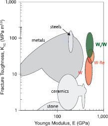
Figure 17. Ashby diagram of fracture toughness over Young's modulus based on [178] and [179] and data for tungsten of [54]. In the digram a potential region for Wf/W is shown based on the results presented here. Adapted by permission from Macmillan Publishers Ltd: Nature [179], copyright 2008.
Download figure:
Standard image High-resolution image7.3. Concluding remarks
The availability of robust and durable heat sink and plasma-facing materials suitable for HHF applications is essential in the design of future nuclear fusion devices, like e.g. a DEMO reactor. The known risks that are currently associated with Cu alloys and monolithic W material grades advocate the development of alternatives—possibly including fibre-reinforced composites, as described in this article.
In the first part of this article, two fibre-reinforced Cu-based composite materials that are promising with regard to heat sink applications in highly loaded PFCs have been briefly presented: SiCf/Cu and Wf/Cu. These materials offer advantages in comparison to Cu alloys, which are currently regarded as state-of-the-art PFC heat sink materials: on the one hand, these composites exhibit enhanced high-temperature strength, allowing extended operating temperatures. On the other hand, macroscopic thermomechanical material properties of such composites can be tailored, e.g. to minimise the CTE mismatch between a PFC heat sink and the plasma-facing material. The future application of such materials requires the development and demonstration of industrial scale production technology. Furthermore, theoretical methodology for the modelling of deformation, damage and fracture needs to be established for the formulation of structural failure criteria. Aside from that, comprehensive materials test data, including irradiation tests, are required to support structural design efforts that take such composite materials into consideration
In the second part, Wf/W composites are presented as a new concept for improving the toughness of tungsten by reinforcing it with tungsten fibres. Without restricting the positive properties of tungsten, the new concept overcomes one of the most severe problem for the use of tungsten in PFCs: its brittleness (both as-fabricated and after operational embrittlement). The main features of the material concept have been shown for model systems and first batches of bulk material. These are, in particular, active toughening mechanisms and an increased toughness, as well as resistance to embrittlement. Based on these results, the material was chosen as risk mitigation plasma-facing material in the EU Fusion Roadmap [1, 6]. However, Wf/W is not yet as mature as the above presented Cu based composites, and the next step is to show that Wf/W can be applied in PFCs and show the desired properties—the so called proof-of-concept. A way to realize this by the fabrication of Wf/W-based mock-ups by a CVD process and subsequent HHF testing was recently presented [156, 161]. Important open questions in this respect are the behavior of Wf/W within a fusion environment, e.g. erosion resistance, hydrogen retention or activation and the influence of neutron irradiation on the material properties.
8. Laminates
8.1. Discussion of the principles of ductilization in W laminate materials
For tungsten, the mechanical properties can be significantly improved by cold working—like, for example, by cold rolling. One example of such semi-finished products that have experienced high degrees of cold working are W foils. Their excellent mechanical properties are the starting point for the synthesis of tungsten laminates. (Figure 18, A). W foils have excellent mechanical properties, and are the starting point for the synthesis of W laminates (figure 18, B). The transfer of beneficial foil parameters to a tungsten bulk laminate material, by the synthesis of W laminates, was successful, shifting the DBTT down to lower temperatures (300 °C) compared to pure W plate material [86, 87, 180, 181]. For several applications in the field of high energy conversion, pipes are the requested components. For these cases, W laminate pipes can be produced by wrapping and joining of W and interlayer foils (figure 18, C). Such laminated pipes show extraordinary Charpy impact properties. They essentially enable an advanced helium-cooled divertor concept [35]. An impression of this concept is seen in figure 18, D, where the structural W laminate pipe is embedded in W armour monoblocks and joined at both ends to steel connection plugs. In order to increase the heat-transfer coefficient, the helium jet impingement is realized by an internal steel cartridge.
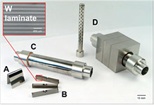
Figure 18. Overview of the different scientific aspects of W laminate materials. A: W foil possesses extraordinary mechanical properties in terms of ductility, toughness and the BDT, that can be related to the positive influence of cold rolling on these properties, as well as to microstructural size effects due to its ultra-fine grained (UFG) microstructure. B: Through the assembly and joining of several layers of W foil, the properties of the foil can be transferred to the bulk. C: Through rolling up and joining, W laminate pipes can be produced. The laminate pipe is joined at both ends to austenitic steel (1.4571). D: Based on a W laminate pipe and its extraordinary properties in terms of toughness and ductility, a pipe-based divertor concept for a helium-cooled divertor can be proposed. This concept makes use of a steel cartridge in order to guarantee the jet impingement that increases the heat-transfer coefficient.
Download figure:
Standard image High-resolution imageWithin the discussion of the principles of ductilization in W laminate materials, three aspects will be focused on. The first issue is the influence of cold working on the mechanical properties such as ductility, toughness and brittle-to-ductile transition (BDT). The second point deals with the mechanical properties of W laminates, and microstructural as well as geometrical size effects. Finally, the third aspect of this discussion deals with the type of energy dissipation mechanism in W laminate Charpy impact test samples and, therefore, the shift of the BDT to lower temperatures compared to pure W plate material.
8.1.1. Cold working.
For both face centred cubic (fcc) and bcc metals, cold rolling leads to an increase in strength combined with a decrease in ductility. This is the well-known state-of-the-art knowledge of materials. However, the behavior of W (and maybe also of molybdenum) does not fit into this classical picture. It was shown by Wei and Kecskes that cold rolling increases strength and ductility [182]. In their paper, they show that the lower the rolling temperature, the higher the strength and ductility. This behavior is a puzzling phenomenon, and needs further explanation.
The second property that is improved by cold rolling is toughness. Pippan et al showed that technically pure W foil with a thickness of 160 m in its as-received condition has a room temperature (RT) fracture toughness of 70 MPa m0.5 (L-T direction) and 60 MPa m0.5 (T-L direction), respectively [183, 184] (L-T and T-L means in-plane orientation, details of the code can be found in [185]). These values are very high compared to the well-known RT fracture toughness of W (5 MPa m0.5) and are in the same regime as W 26 wt.% rhenium (Re) (60 MPa m0.5, [54, 186]). Whereas for W 26 wt.% Re the origin of the high fracture toughness can be found in the formation of a beneficial solid solution, the high toughness of W foils can only be related to its microstructure, and the change of the microstructure during cold rolling. Finally, cold working has a significant impact on the BDT. Again W does not fit the classical picture, as for W the BDT can be shifted to a lower temperature through cold rolling [187] while, for example, the BDT of α-Fe increases after cold working.
In summary, the material response of W to cold rolling improves ductility, toughness and BDT, and therefore, highly deformed cold-rolled W foils appear to be interesting candidates for the synthesis of W laminates.
8.1.2. Size effects.
Discussing the extraordinary properties of W foil, size effects have to be considered [188–190]. These include, for example, microstructural size effects. The high degree of cold rolling leads to pancake-shaped grains with typical dimensions of  μm3. This means that in the direction of the thickness of the foil, the grain size is in the so-called intermediate grain size (GS) regime; the ultra-fine grained (UFG) regime, which is between nano crystalline (GS < 100 nm) and coarse grained (GS > 1 m) [189]. Valiev et al showed that UFG materials produced by severe plastic deformation show paradoxically increased strength and ductility [191]. The underlining microstructural mechanisms of the increase in ductility are not yet understood, but are intensively discussed [192]. Considering microstructural size effects, one has to admit that even the most popular size effect, the Hall–Petch effect, cannot be completely explained in detail [193].
In fully recrystallized W foil another size effect comes into play. In this condition, the grain size equals or even exceeds the foil thickness. In other words, single grains span the whole cross-section from one surface to the other. This, in turn, enables another deformation mechanism. Here, dislocations can easily move (since there are no grain boundary obstacles) to the surface, where they are annihilated (figure 19, left). This mechanism increases the plasticity significantly and might also take place in W–Cu laminate interfaces [180, 181].
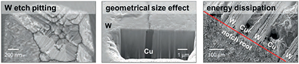
Figure 19. The scanning electron microscope (SEM) picture on the left shows an etch pit of a W screw dislocation penetrating the surface. Especially on W foil in its recrystallized condition, etch pits on forest dislocations are feasible. The SEM picture in the middle shows a perpendicular focused ion beam (FIB) cut of a W–Cu laminate with a Cu interlayer of one micrometer. In this way, a geometrical size effect is created as the dislocations in the Cu interlayer are channelled. The SEM picture on the right gives an impression of the complex fracture behavior of W laminates and their energy dissipation mechanisms. The sample shown here was in L-T orientation, and the energy was dissipated by plastic deformation of the W and Cu foil only, as in this orientation any crack deflection or surface creation can be neglected.
Download figure:
Standard image High-resolution imageFinally, especially for a W–Cu laminate, a geometrical size effect can be provoked, that is, if the Cu interlayer is smaller than 1 μm (figure 19, middle). According to the W–Cu phase diagram, there is (in good approximation) no diffusion of W into Cu and vice versa. So a W–Cu interface can be regarded as a sharp bcc–fcc interface. If the dislocations in the Cu interlayer are meant to glide, they are restricted on both sides by W layers. This forces the dislocations to move in the W channel, which might lead to a significant increase in strength of the Cu interlayer, and thus of the W–Cu laminate.
8.1.3. Energy dissipation.
In the development of advanced ceramic materials, the toughness was successfully increased by applying ceramic fibres in a brittle ceramic matrix. The increase in the toughness can be explained by some bridging effects as well as by the energy dissipation through the creation of new surfaces along the crack paths. Energy dissipation by surface creation also takes place in W laminates, especially when samples are tested in the X-S orientation (stress field perpendicular to the interfaces). For such samples, the crack is subsequently deflected, and has to be initiated layer by layer [181]. This crack deflection not only comes along with the creation of a surface but also with a subsequent change in the stress state at the crack tip. A deflected crack moving away from the ligament plane results in a preferable stress tensor in terms of crack propagation.
However, the contribution of energy dissipation by crack deflection to the total energy dissipation should be negligible. Most energy is dissipated by plastic deformation of the foil—and here mainly of the W foil [86]. Especially when samples are oriented in the L-T direction (figure 19, right), crack deflection does not take place. So, an improvement in dissipated energy compared to the pure plate material must be sought in the mechanical properties of the W foil or the interlayer. Considering Pippan et al's results for the high fracture toughness of W foil at RT, it is no surprise that L-T oriented samples also show advanced fracture behavior.
It can be concluded that the fracture behavior of W laminates is complex and depends on several parameters, but that the excellent properties of cold rolled W foil might be the dominating aspect in the discussion of energy dissipation.
8.2. Current status of the development of W laminate materials
The synthesis of W laminates addresses questions of (i) how to remove the W oxide layers such as  ,
,  ,
,  or
or  , (ii) which interlayer to use (W-X phase diagrams, solid solutions, intermetallic phases, line compounds) and how to apply them (physical vapour deposition, foil, paste, powder), (iii) which joining technology to select (brazing, diffusion bonding, or others) and finally (iv) the stability of the interface after joining and ageing. The thermo-mechanical properties of a W laminate do strongly depend on the type of interlayer and joining technology. The discussion on synthesis strategies for high performance W laminates can be found elsewhere [181]. Using Cu as the interlayer leads to a material with a high thermal conductivity and sharp interfaces in terms of phase transition or chemical composition. These sharp interfaces appear to be preferable with regard to ageing, so the Kirkendall effect is not likely to take place, and even after the operation of the divertor at full power for two years the interface should still be sharp.
However, copper melts at as low as 1085 °C. With a melting point of 1910 °C, vanadium (V) is an interesting alternative interlayer material. Moreover, the W–V phase diagram shows no intermetallic phases, no line compounds and no miscibility gaps. Charpy impact results of W–V laminates are shown in figure 20.

Figure 20. Left: The results of the Charpy impact tests of W–Cu, W–V, W–Ti and W–Pd laminates are compared to bench mark experiments made on pure W plate material and W–AgCu laminates. More details on the benchmark experiments can be found elsewhere [16, 86]. Middle: A W–Ti interface shows complex structures that are caused by different diffusion coefficients as well as the mono-eutectic reaction. Right: The deep drawing of a W–Cu laminate is possible, and can be used as well as a W laminate pipe for several divertor concepts.
Download figure:
Standard image High-resolution imageThe melting point of titanium (Ti)—another possible candidate as a W laminate interlayer material—is 1668 °C. Analyses of the diffusion and inter-diffusion coefficients (Darken equation) of W in Ti and Ti in W show that there is much higher diffusion of W in Ti than vice versa. Combined with the miscibility gap of the W–Ti phase diagram, this leads to complex structures of the W–Ti interface, that now suffers from ageing (figure 20, middle). The results of the Charpy impact properties show that the two most promising candidates are W–Cu and W–V laminates (figure 20, left) and these will be further assessed in detail.
Using W laminates as a structural material for pressurized parts, the fabrication of pipes or thimbles has to be feasible. The fabrication of W laminate pipes is possible and can be seen in figure 18. But also the fabrication of W–Cu laminate thimbles is feasible [81]. Both, pipes and thimbles can now be used as components for several divertor concepts.
8.3. Applications for W laminate pipes within and apart from nuclear fusion
One of the most relevant challenges with regard to laminates for structural applications is the stabilization of the UFG microstructure of the W foils and, therefore, the conservation of the mechanical properties. This stabilizing of the microstructure can be realized by using so-called 'non-sag' W, which is technically pure W with 30–70 ppm potassium (WVM) content. This material is well known and used in the bulb industry, which is where the name 'non-sag' comes from. The stabilizing of the microstructure is realized by the formation of potassium-filled bubbles that surround the grains. These bubbles realize an interlocking of the microstructure. According to this microstructural stabilizing mechanism, the higher the degree of cold working, the finer dispersed the K bubbles, the higher the recrystallization onset temperature [194]. This behavior is in contrast to pure W, where an increase in cold working leads to a decrease in the recrystallization temperature (figure 21). Furthermore, potassium doped W shows better creep performance compared to pure W [78]. So, for any technical high-temperature application, non-sag W is the first option.

Figure 21. Left: The measurement of hardness over temperature gives an impression of the recrystallization behavior of technically pure W and potassium-doped tungsten. This diagram shows that there is a slight benefit of the 'non-sag' W compared to pure W and that there is still place for improvement in the material's development. Middle and left: The different recrystallization behaviors of both W materials can also be found in the microstructure as shown by the SEM pictures.
Download figure:
Standard image High-resolution imageConsidering W laminates in the fusion environment, it was Armstrong and Britton who found that UFG W foil has an improved radiation resistance compared to bulk W products. Armstrong and Britton explain these differences in radiation response by the increased sinks for damage in the highly rolled W foil [195].
Thinking about the use of W laminate pipes for innovative high temperature applications outside fusion, the W oxidation issue has to be addressed [22]. Applications can then be found in the fields of concentrated solar power, the alkali metal thermal-to-electric energy conversion, or the production of customized fuels from biomass, such as dry straw or wood [196]. It can be concluded that W laminate pipes show extraordinary mechanical properties, and—therefore—have the potential to be used in advanced energy conversion systems. However, the underlying microstructural mechanisms are still not fully understood in detail, which leaves room for further improvement and reason for continuing investigations.
9. Mechanically alloyed tungsten
9.1. Methodology for ductilization in Mo bicrystal
Molybdenum bicrystals with  symmetrically tilt GBs or
  twist GBs with controlled misorientations and no detectable Auger peaks of any of the interstitial gaseous elements were prepared by the radio-frequency floating zone melting method and subjected to four-point bending tests at 77 K to suppress the effect of plastic deformation on the fracture behavior. It was found that the intergranular embrittlement is significantly dependent on GB misorientation, and the GB misorientation dependence of GB fracture stress is surprisingly similar to that of plastic strain to fracture, but not to that of yield stress (figure 22) [37, 40]. This result is important because it tells us that intergranular embrittlement may be overcome by reinforcing the embrittling GBs.
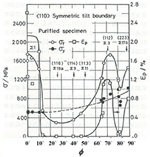
Figure 22. Fracture stress,  , yield stress,
  , and plastic strain to fracture,
  , versus misorientation angle, ϕ, for purified Mo bicrystals with
  symmetric tilt boundaries where no Auger peaks of impurity elements are detected [37, 40]. Adapted with permission from [37].
Download figure:
Standard image High-resolution imageEffects of addition of each of carbon, nitrogen and oxygen on GB fracture stress and ductility for the most embrittling GB (the misfit angle of ≈ ) were studied. It was shown that carbon in solution and precipitation (
 ) at the GB has a beneficial effect on ductility enhancement due to increase in the interatomic cohesion at the GB, but the other elements have detrimental effects [38, 40].
Although the effect of Ti addition on intergranular embrittlement in Mo was not fully investigated at that time, the authors examined the effect of 1.5 mol% TiC (≈1 wt.% TiC) addition on ductilization for the Mo bicrystals with the  twist GB of the most embrittling orientation. It was shown that the effect of TiC addition is more beneficial than that of C addition: The GB fracture stress at 77 K for Mo–1.5 mol% TiC reaches 1.8 GPa, which is three times higher than that for pure Mo (0.6 GPa) and 1.5 times higher than for 0.015% C added Mo (1.2 GPa). As a result, the temperature where full bending occurs is reduced to 197 K for Mo–1.5 mol% TiC from 268 K for pure Mo (figure 23) [39, 40].
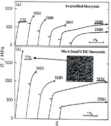
Figure 23. Four-point bending stress strain curves at temperatures at and below room temperature for (a) as-purified Mo bicrystals and (b) Mo–1.5 mol%TiC bicrystals together with a SEM micrograph showing the grain boundary (GB) fracture surface broken at 77 K. Both bicrystals have the most embrittled  twist boundary of misorientation of 34° [39, 40]. Adapted with permission from [39].
Download figure:
Standard image High-resolution imageThe fracture surface of Mo–1.5 mol% TiC broken at 77 K exhibited a high density of precipitates of titanium carbide with a preferable orientation relationship with the Mo matrix [39, 40]: the Kurdjumov–Sachs (K–S) orientation relationship at the interface between the TiC phase and Mo matrix meets

TiC exhibits a high melting point (∼3520 K) and a capability for self-adjustment of the lattice constant by forming a solid solution with W and leaving a non-stoichiometry of  [197].
The occurrence of TiC precipitates at the GBs always follows the equilibrium segregation of the TiC constituents at the GBs. The beneficial effect of Ti addition on ductilization was also reported [198]. Therefore, the observed benefit of 1.5 mol% TiC addition can be attributed to the increased GB cohesion by the precipitation of TiC and segregation of the TiC constituents at GBs.
9.2. Ductilization in nanostructures
9.2.1. Target nanostructure and microstructure control.
Radiation induced lattice defects impede glide motion of dislocations, resulting in increase in yield stress (radiation hardening), and also may change the structure and chemical compositions of random GBs from the controlled conditions, thereby causing radiation embrittlement. In order to suppress radiation embrittlement, it is necessary to introduce a high density of sinks for radiation induced defects. Effective sinks are GBs and dispersoids. Therefore it follows that a structure containing ultrafine grains and a high density of dispersoids is the target structure and called nanostructure.
TiC is one of the dispersoids effective for the above purpose; TiC precipitated in the grain interior will work as sinks for radiation-induced defects. A high density of GBs is introduced due to grain refinement by heavy plastic working at temperatures where recrystallization does not occur. However, dispersoids in metals disturb plastic working (dispersion strengthening), and grain refinement becomes more difficult with increase in dispersoids and decrease in grain size (grain size strengthening). Moreover, a high free energy due to fine-grained structures may lead to recrystallization and grain growth at elevated temperatures. It is therefore our main objective to achieve grain refinement with thermal stability in the recrystallized state, without relying on plastic working for dense composites.
In view of the target structure, the results on Mo–1.5 mol% TiC bicrystals can be an encouraging reference: the precipitation of TiC and segregation of the TiC constituents occur at each of all the GBs and grain interior. As the grain size decreases, the GB area significantly increases with 1/d (d being the grain diameter). Intergranular embrittlement will occur even when only one unreinforced GB is left, and hence all of the GBs must be reinforced by the behavior of TiC (segregation and precipitation).
Nanostructures are practically producible by the powder metallurgical (PM) route. In order to attain the target nanostructure by the PM route, the following microstructure control is required; (1) to produce alloyed powder of a solid solution of W–Ti–C with nanosized grains from the starting powders of W and TiC, and (2) to produce fully densified compacts of equiaxed ultra-fine grains of W matrix containing a high density of fine precipitates of TiC at GBs and grain interior from the alloyed powders of W–Ti–C.
If the oxygen level is appreciably high, the oxygen preferentially reacts with Ti to form titanium oxides because the standard free energy for the formation of titanium oxides is much lower than that of TiC [199]. As a result, carbon atoms left behind in the W matrix would react with the surrounding W atoms to form W2
C (W2
C is known to be a brittle phase): the nucleation and growth of a metal carbide or metal oxide requires diffusion of metal elements as well as carbon or oxygen. Since carbon or oxygen atoms are surrounded by the metal matrix atoms, of which diffusivity is much lower, it is difficult to attain the equilibrium state where the brittle  phase is not formed.
9.2.2. MA-HIP.
Mechanical alloying (MA).
In order to attain the above item (1) MA will be the most effective: MA is the method for producing alloyed powder with nanosized grains (less than 30 nm) in solid solution of several elements that are thermodynamically insolvable in each other (or extremely limited in solubility) [200, 201]. Therefore, if the processed powder is not alloyed powder, but just comminuted and/or dispersed powder from the starting powder, the process should be called MD (Mechanical Dispersion), not MA.
Prior to the MA operation, the mixed powders are degassed by heating at around 1273 K for 1 h in vacuum. The degassed powders are put in a metal vessel with hard balls in a purified H2 or Ar atmosphere and then subjected to high energy ball milling by rotating or vibrating the vessel in an ambient temperature. Figure 24 shows a schematic illustration of the MA process consisting of three stages of powder evolution, i.e. severe plastic deformation and work hardening, fracture and cold joining at freshly revealed fracture surfaces, and homogenization. Powder that has completed all these stages is called mechanically alloyed powder (MA powder).
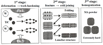
Figure 24. Schematic illustration of MA (mechanical alloying) process consisting of three stages.
Download figure:
Standard image High-resolution imageMA always admits contamination by metal impurities introduced from the milling vessels and balls used for MA. Therefore, the vessel and balls must be made of materials acceptable from the viewpoint of ductility, thermal stability, radioactivity, etc. The MA vessels and balls that the authors employed were made of TZM (Mo–0.5Ti–0.1Zr–0.01C).
It is also important to use high purity powders without any lubricants, and prevent contamination with gaseous interstitial impurities of oxygen and nitrogen contained in the atmospheres through the fabrication process. For this, the powders are always treated in a well degassed glove box filled with a purified Ar or H2 gas.
Hot isostatic pressing (HIP).
For attaining item (2), HIP seems the most effective: HIP permits consolidation of the MA powder without exposure to air and at relatively low temperatures, where grain growth may not occur. During the consolidation, the solutes of C and Ti diffuse to react to form precipitates of TiC at GBs and grain interior.
For this, the MA powder was at first heated in vacuum at 1173 K for 3600 s to eliminate the H2 or Ar introduced into the powders by MA, and then charged into a capsule made of mild steel (25 mm in diameter and 53 mm in height) in the glove box. The capsule containing the powder was sealed by TIG welding during outgassing at temperatures from room temperature to 1023 K in a vacuum better than 3  torr and then subjected to HIP. This outgassing process is critical to achieve the full densification of HIPed compacts, especially for W [202]. HIP was conducted in an Ar atmosphere for 3 h at 1573 K and 196 MPa for Mo alloys and at 1623 or 1673 K and 196 or 980 MPa for W alloys.
MA-HIPed refractory alloys.
Since the low temperature ductility of MA-HIPed refractory alloys is considerably affected by the atmosphere in MA, we designate the compacts as Alloy/Ar or Alloy/H, which denotes the sealed gas in the MA process, Ar or H2, respectively [42].
As stated in section 9.2.1, our main objective is to achieve grain refinement with thermal stability in the recrystallized state without relying on plastic working. On the other hand, for many years the authors had believed that ductilization in any PM fabricated nanostructured alloys requires plastic working (PW) such as hot forging and hot/warm rolling following MA and HIP. As a matter of fact, a nanostructured Mo–0.2% TiC/Ar alloy that was at first fabricated by MA-HIP exhibited an enhanced low temperature ductility following PW [203]. However, increased TiC addition up to 1.0 wt.% (1.5 mol% TiC same as figure 23) often disturbed PW and the benefit of PW was poor [204, 205].
Controlled neutron irradiations on a pre-embrittled Mo alloy imparted a very interesting and encouraging result [205–208]. When the MA-HIPed Mo–1.0% TiC/Ar with insufficient PW was exposed to controlled temperature-cycle irradiations in JMTR (Japan Materials Testing Reactor) between 573 and 773 K with fluence of 1  n m−2 (En
> 1 MeV) and subjected to three-point impact bending (5 m s−1) and Vickers microhardness tests, it exhibited remarkable ductilization regardless of significant radiation hardening (figure 25) [205–208]. This ductility enhancement is quite opposite to radiation embrittlement and was designated as RIDU (Radiation Induced DUctilization) [206, 207]. The only possible explanation for RIDU is that all of the possible cracking sites such as random GBs and interfaces of dispersoids are significantly reinforced by the neutron irradiation, and the beneficial effect of the reinforcement exceeds the embrittling effect of radiation hardening. The reinforcement due to neutron irradiation can be attributed to radiation-enhanced or -induced precipitation of Mo2C, (Mo, Ti)2C, TiCx, (Ti, Mo)Cx and their segregation, which may occur preferentially at random GBs with higher energies [207, 208]. It is noted that radiation induced point defects distribute very homogeneously in the material, and significantly promote lattice diffusion towards the state of lower free energies. Similar results on RIDU were reported for Mo–0.2TiC/Ar, although the degree of RIDU is much smaller than that for Mo–1.0TiC/Ar [206, 209].
n m−2 (En
> 1 MeV) and subjected to three-point impact bending (5 m s−1) and Vickers microhardness tests, it exhibited remarkable ductilization regardless of significant radiation hardening (figure 25) [205–208]. This ductility enhancement is quite opposite to radiation embrittlement and was designated as RIDU (Radiation Induced DUctilization) [206, 207]. The only possible explanation for RIDU is that all of the possible cracking sites such as random GBs and interfaces of dispersoids are significantly reinforced by the neutron irradiation, and the beneficial effect of the reinforcement exceeds the embrittling effect of radiation hardening. The reinforcement due to neutron irradiation can be attributed to radiation-enhanced or -induced precipitation of Mo2C, (Mo, Ti)2C, TiCx, (Ti, Mo)Cx and their segregation, which may occur preferentially at random GBs with higher energies [207, 208]. It is noted that radiation induced point defects distribute very homogeneously in the material, and significantly promote lattice diffusion towards the state of lower free energies. Similar results on RIDU were reported for Mo–0.2TiC/Ar, although the degree of RIDU is much smaller than that for Mo–1.0TiC/Ar [206, 209].
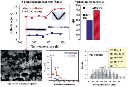
Figure 25. Radiation induced ductilization (RIDU) observed in nanostructured Mo–1.0%TiC irradiated with neutrons in JMTR (Japan Materials Testing Reactor) and size distribution of several precipitate phases after irradiation [205–207]. Adapted from [205], Copyright 1996, with permission from Elsevier.
Download figure:
Standard image High-resolution imageThe above reinforcement mechanism in RIDU is essentially the same as the one already shown in the unirradiated Mo bicrystals. Therefore, RIDU tells us that we have achieved the target nanostructure where all of the GBs are reinforced by the behavior of TiC and its solid solutions (segregation and precipitation).
Successful ductilization of nanostructured Mo alloys without PW and neutron irradiation after consolidation by HIP or spark plasma sintering (SPS) was performed by Takida et al [210]. They examined the effects of addition of 0.8 mol% transition metal carbides (TMCs) other than TiC on the DBTT through three-point impact bending. They found that the ductilization of Mo–0.8 mol% TMC/Ar depends strongly on the kind of dispersoids, and TaC addition appeared to be more effective than TiC addition. In this case, however, more addition of 1.6 mol% TMC resulted in less ductilization.
Efforts to fabricate nanostructured W alloys by MA-HIP-PW were also made. The capsule initially employed for HIP at higher temperatures was pure Ta with much higher melting point (3263 K) than mild steel (≈1760 K). However, PW for MA-HIPed W alloys was much more difficult than for MA-HIPed Mo alloys: Only the (0.2–0.3)% TiC added W alloys were subjected to sufficient PW, which lead to the relative density of 99.5% and an enhanced ductility at lower temperatures measured by three-point impact bending [211, 212].
The above results on enhanced ductility suggested that the ductilization of nanostructured refractory alloys can be achieved by increasing the relative density to ≈99.5% or more. In order to increase the relative density of MA-HIPed W with TiC additions, therefore, an improvement in all the processes of MA and HIP was made to seek thorough removal of impurities that are likely responsible for less densification: especially important were degassing of the starting powder and MA powder and outgassing of the residual gas in the capsule (mild steel) charged with the MA powder prior to TIG welding of the capsule [202], as mentioned in paragraph HIP in Section 9.2.2.
As a result, HIPing at 1623–1673 K, approximately 2/5 of the melting point, resulted in essentially fully densified compacts with relative densities of 98–99% depending on the sealed gas in MA. The MA-HIPed compacts of W–(0.25–1.5)% TiC exhibited equiaxed grains with the average diameter of 50–200 nm in the recrystallized state and were designated as UFGR (Ultra-Fine Grained, Recrystallized) W–(0.25–1.5)TiC (/H and /Ar) [42, 202].
The UFGR W–(0.25–1.5)TiC has attracted great attention because such a nanostructure was the first to fabricate in W materials. Characterization of the UFGR W–(0.25–1.5)TiC was performed by domestic and international research collaborations. Regarding the ductilization, however, no appreciable ductility occurred at room temperature and the DBTT defined as the null-ductility temperature was as high as ≈830 K. Figure 26 shows the effects of TiC addition, MA atmosphere and HIP pressure on three-point bend fracture stress at room temperature [42, 213]. TiC addition of 0.25% significantly increases the fracture stress, but further TiC additions up to 1.5% do not change the fracture stress. Moreover, HIPing for W–1.1TiC/Ar at the increased pressure of 1 GPa (UH) increases the fracture stress to 2.6 GPa mainly due to the significant suppression of nano-sized Ar bubbles. These results indicate that the beneficial effects of TiC additions are masked probably by residual pores and insufficient reinforcement of random GBs and dispersoid interfaces.

Figure 26. Effects of TiC addition, MA (mechanical alloying) atmosphere and HIP (hot isostatic pressing) pressure on three-point bend fracture stress at room temperature at a displacement rate of  mm s−1 for UFGR (ultra-fine grained, recrystallized) W–(0–1.5)%TiC (/H and /Ar). UH and NH stand for HIP at an ultra high pressure of 1 GPa and at a normal high pressure of 0.2 GPa respectively [42, 213]. Adapted from [213], Copyright 2010, with permission from Elsevier.
Download figure:
Standard image High-resolution imageDuctilization of materials does not occur until the fracture stress exceeds the yield stress. A rough estimate of the yield stress assuming the Hall Petch relation for W gives as high as 5–6 GPa for UFGR W with the grain size of ≈100 nm. It seems quite difficult to enhance the fracture stress to above 5–6 GPa. Therefore, in order to achieve ductilization of nanostructured W, the following microstructure control is required in addition to MA-HIP. That is, to significantly promote the precipitation of TiC and segregation of the TiC constituents at all of the random GBs, grow the grains to appropriate sizes to reduce the extremely high yield stress due to grain size strengthening to the required level and thoroughly remove the residual pores. For this purpose, a new process for microstructural control, designated as grain boundary sliding-based microstructural modification (GSMM), was developed.
9.2.3. MA-HIP-GSMM or MA-GSMM.
Grain boundary sliding-based microstructural modification (GSMM).
GSMM is based on activation of GB sliding without crack formation and its linkage, where the recrystallized, equiaxed grain geometry is maintained and the deformation is driven by active grain rotation and extensive relative displacement of the adjacent grains accompanied with moderate grain growth [42]. These GB activities would lead to the sufficient precipitation of TiC and segregation of the TiC constituents at the random GBs, thereby reinforcing the GBs with holding the recrystallized state. It may also have the effect of removing the residual pores through GB diffusion during GB sliding. In addition, the moderate grain growth caused by GSMM leads to the decrease in yield stress to an appropriate level.
GSMM is performed under the condition that the above GB activities are the largest. Such GB activities are expected to occur during superplastic deformation where sufficiently large elongation without crack formation and its linkage and relatively low flow resistance are assured. Therefore, the superplastic behavior of W–(0.25–1.5)TiC (/H and /Ar) was examined as a function of TiC content, MA atmosphere, temperature and strain rate (figure 27) [42, 214–216]. The optimum conditions of GSMM turned out to be (1.1 ∼ 1.2)% TiC addition and plastic strain rate of 10−5 s−1 at 1923–1973 K.
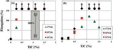
Figure 27. Tensile elongation at 1773, 1873 and 1973 K at an initial strain rate of  s−1 as a function of TiC content for (a) ultra-fine grained, recrystallized (UFGR) W–(0–1.5)TiC/H and (b) UFGR W–(0–1.5)TiC/Ar. The arrows indicate elongation exceeding 160% [42, 214] Adapted from [214], Copyright 2009, with permission from Elsevier.
Download figure:
Standard image High-resolution imageToughened, fine-grained, recrystallized (TFGR) tungsten materials.
Mechanical properties and microstructure.
GSMM processes by compression were applied to MA-HIPed (UFGR) W–1.1TiC (/H and /Ar) as a function of temperature and reduction ratio. It was found that significant increase in fracture stress and ductilization at room temperature are achieved when GSMM was performed at temperatures of 1923–1973 K and reduction ratio above 80% (figure 28) [42, 213]. The GSMM processed W–1.1TiC (/H and /Ar) is designated as TFGR (toughened, fine-grained, recrystallized) W–1.1TiC [42].
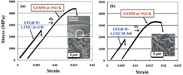
Figure 28. Three-point bending stress strain curves at room temperature and  mm s−1 for (a) W–1.1TiC/Ar-UH and (b) W–1.1TiC/H-NH before and after GSMM (grain boundary sliding-based microstructure modification) at 1923 K to approximately 80% in reduction ratio.
  indicates the proportional limit (yield stress). UH and NU stand for hot isostatic pressing (HIP) at 1 GPa and 0.2 GPa respectively. SEM micrographs of fracture surface are also shown [42, 213]. Adapted with permission from [42]. Adapted from [213], Copyright 2010, with permission from Elsevier.
Download figure:
Standard image High-resolution imageThe DBTT (nil ductility temperature) for TFGR W–1.1TiC/H is shown in figure 29 as a function of impurity contents of oxygen and nitrogen [217]. The DBTT decreases with decreasing oxygen content and is between 240 and 420 K for oxygen contents of 160–870 wppm. Since the DBTT of UFGR W–1.1TiC/H is ≈830 K, GSMM leads to significant reduction in DBTT.
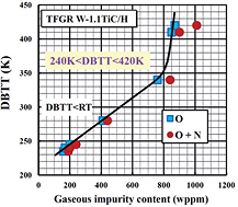
Figure 29. DBTT (ductile-to-brittle transition temperature) for TFGR (toughened, fine-grained, recrystallized) W–1.1TiC/H as a function of impurity contents of oxygen and nitrogen. The DBTT is defined as the nil ductility temperature assessed from the temperature dependence of plastic strain to fracture as measured by three-point bending [217]. © The Royal Swedish Academy of Sciences. Adapted by permission of IOP Publishing. All rights reserved.
Download figure:
Standard image High-resolution imageFigure 30 shows that promoting segregation and precipitation of TiC, GSMM significantly increases the amount of dispersoids [42]. On the other hand, increase in oxygen content leads to the formation of the brittle W2C phase, which may act as initiation sites of cracking. Since an excessive amount of oxygen disturbs the recombination of decomposed TiC through the formation of the W2C phase and a Ti oxide as mentioned in section 9.2.1, it is necessary to control the oxygen content to an acceptably low level.
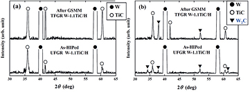
Figure 30. X-ray diffraction (XRD) patterns for TFGR (toughened, fine-grained, recrystallized) and UFGR (ultra-fine grained, recrystallized) W–1.1TiC/H with (a) low (160 mass ppm) and (b) high oxygen (850 mass ppm) contents. It is noted that GSMM (grain boundary sliding-based microstructure modification) significantly promotes TiC precipitation [42]. Adapted with permission from [42].
Download figure:
Standard image High-resolution imageTEM microstructures and GB orientations analyzed by electron back scatter diffraction (EBSD) patterns for the above UFGR and TFGR W–1.1TiC (/H and /Ar) are shown in figure 31. Leaving the grain shape equiaxed, GSMM at 1923 K increases the grain size almost by one order: 0.6 μm for W–1.1TiC/Ar and 1.5 μm for W–1.1TiC/H [42, 218, 219]. The distribution of most of the GB orientation obeys the Mackenzie curve based on the random distribution of grain orientation, indicating that most of the GBs are random GBs of high energy. No visible nano-sized bubbles are observed in TFGR W–1.1TiC (/H and /Ar).
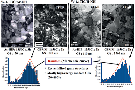
Figure 31. TEM bright field images depicting the grain structures and the grain boundary orientation of UFGR (ultra-fine grained, recrystallized) and TFGR (toughened, fine-grained, recrystallized) W–1.1TiC/Ar-UH and W–1.1TiC/H-NH. GS stands for the average grain size [42]. Adapted with permission from [42].
Download figure:
Standard image High-resolution imageEffects of GSMM on the formation and growth of dispersoids in TFGR W–1.1TiC/H are shown in figure 32 [220]. The average size of dispersoids is larger at GBs than in grain interior, and increases with increasing GSMM temperature: 90 nm in the grain interior and 160 nm at the GBs for GSMM at 1923 K; 160 nm in the grain interior and 390 nm at the GBs for GSMM at 2273 K. In those GSMM processed specimens, the K-S orientation relationship was recognized at the interface between the TiC phase and W matrix [221].
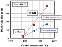
Figure 32. Effects of GSMM temperature on the average size of TiC dispersoids in the grain interior and at grain boundaries for UFGR and TFGR W–1.1TiC/H [220]. © The Royal Swedish Academy of Sciences. Adapted by permission of IOP Publishing. All rights reserved.
Download figure:
Standard image High-resolution imageThe main features of TFGR W–1.1TiC/H are listed in table 3, in comparison with commercially available pure W (e.g. ITER grade W).
Table 3. Features of TFGR (toughened, fine-grained, recrystallized) W–1.1TiC.
| Characterization item | TFGR W–1.1TiC | Commercially available pure W |
|---|---|---|
| Microstructure | Equiaxed, fine grains | Elongated, relatively coarse grains |
| TiC fine dispersoids | No dispersoids | |
| Recrystallized state | Stress-relieved state | |
| High sink density | Low sink density | |
| Grain boundary in the recrystallized state | Significantly reinforced by TiC precipitation and its segregation | Weak (not reinforced) |
| Recrystallization temperature | Already recrystallized | 1200–1300 °C (Tmelt 3410 °C) |
| DBTT in the recrystallized state | Around RT | higher than RT |
| Response to high heat loading | Resistant to cracking and surface roughening | Prone to cracking and surface roughening |
| Radiation damage | Resistant | Vulnerable |
The densification (consolidation) of the MA powder can also be performed by the GSMM process. That is, the HIP process may be replaced with GSMM when consolidation by the GSMM is initially performed at a temperature similar to the HIP temperature (first step of GSMM), and GSMM is then performed as in the above MA-HIP-GSMM (second step of GSMM). The first and second steps of GSMM can be successively performed by merely changing the temperature. This more time saving and economical method, without HIP, is designated as the MA-GSMM process [217]. TEM microstructures and bend ductility at room temperature showed that MA-GSMM processed W–1.2% TiC/H exhibits essentially the same features as the MA-HIP-GSMM processed W alloys [217]: The grain structures are essentially recrystallized, equiaxed with average grain size of ≈2 μm and TiC exists at GBs and grain interior with the K-S orientation relationship between the W matrix. Three tested specimens exhibit appreciable, reproducible ductility at room temperature.
Mechanical and plasma-wall interaction behavior.
The structural applications of the materials to the first wall require assured resistance to mechanical loads without any deformation and cracking. The performance of TFGR W–1.1TiC observed upon thermal shock loading and thermal fatigue loading, which are anticipated mainly in divertor environments, indicates its applicability in first wall environments, because thermal shock and thermal fatigue loadings dynamically and statically generate thermal internal stresses due to a temperature gradient in the material.
Thermal shock tests were conducted for TFGR W–1.1TiC/H with oxygen contents of 160 and 850 wppm and UFGR W–0.5TiC/H (oxygen content: 170 wppm) by using JUDITH-1 under the condition of ITER-ELM (edge-localized mode) like loading; t (pulse length) = 1 ms, P (heat density) = 1.1 GW m−2 ( (resultant surface temperature increase) ≈2270 K),
  (base temperature) = 373 K, n (repeated pulse number) = 100. TFGR W–1.1TiC/H with 160 ppm oxygen exhibited no cracks on the surface, whereas TFGR W–1.1TiC/H with 850 ppm oxygen showed tiny and very shallow cracks on the surface, and UFGR W–0.5TiC/H exhibited net-pattern like cracks on the surface and a semi-circle flaw in the interior with a maximum depth of 0.17 mm [31]. TFGR W–1.1TiC/H with 160 ppm oxygen, even when the base temperature was decreased to room temperature, did not exhibit any cracks on the surface.
Thermal fatigue tests were performed for TFGR W–1.1TiC/H and ITER grade, stress relieved pure tungsten (W/SR) by using electron beam irradiation with the following two heating patterns imposed consecutively; (1) surface temperature of around 1973 K, duration of 180 s and (2) repeated irradiations of 2 s irradiation and 8 s rest in one cycle of 10 s for about 1 h in total, which resulted in temperature variations between 1523 and 723 K with 380 cycles. W/SR exhibited significant surface roughening (plastic deformation) and cracking, whereas TFGR W–1.1TiC/H did not exhibit any surface roughening or cracking (figure 33) [222]. The observed behavior of TFGR W–1.1TiC/H can be attributed to high dynamic yield stresses due to grain size strengthening and high fracture stresses due to reinforcement in GBs enriched with TiC and its constituents. These results suggest that TFGR W–1.1TiC/H will be resistant to mechanical loading to be generated in the first plasma wall environments.

Figure 33. SEM micrographs showing the surfaces of (a) ITER grade W and (b) TFGR (toughened, fine-grained, recrystallized) W–1.1TiC/H that were exposed by steady-state heat-loading at 1973 K for 180 s followed by 380 repeated heat loading for 1 h resulting in temperature variation between 1523 and 723 K [222]. Adapted from [222], Copyright 2013, with permission from Elsevier.
Download figure:
Standard image High-resolution imageBehavior under neutron irradiation.
As far as the dispersoids and GBs are stable against neutron irradiation and effectively act as sinks for radiation induced point defects, the nanostructured W materials are expected to exhibit less hardening and less embrittlement due to neutron irradiation. A good example of the beneficial effects of nanostructures on the significant suppression of radiation embrittlement is found in oxide dispersion strengthened (ODS) ferritic steels irradiated with fast neutrons to  nm−2 at 646–845 K in Joyo operating at JAEA. The DBTTs measured by Charpy impact testing did not shift to higher temperatures by the irradiation [224].
Similar results on radiation hardening were found and are shown in figure 34 [208, 223] where the size and number density of radiation induced defects and the increase in Vickers microhardness by irradiation are compared between UFGR W–0.5TiC (/H and /Ar) and commercially available pure W in the stress relieved state (W/SR) irradiated at 873 K up to 2 × 1024 nm−2 (En > 1 MeV) in JMTR. The degrees of the microstructural changes and radiation hardening for the UFGR W–0.5TiC (/H and /Ar) were significantly reduced compared with those for the W/SR. These results reflect the beneficial effect of a high density of sinks contained in UFGR W–0.5TiC (/H and /Ar).
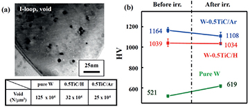
Figure 34. Effects of neutron irradiation on (a) microstructures and (b) Vickers microhardness for UFGR (ultra-fine grained, recrystallized) W–0.5TiC (/H and /Ar), together with stress relieved pure W. Neutron irradiation was performed to a fluence of  nm−2 at 873 K in JMTR [223]. Adapted from [223], Copyright 2008, with permission from Elsevier.
Download figure:
Standard image High-resolution imageApplicability of MA-HIP-GSMM to other nanostructured alloys.
We further examined the applicability of GSMM to ductilization in other nanostructured alloys that contain a high density of random GBs and dispersoids and a small amount of residual pores, but do not exhibit intergranular embrittlement like group VIA transition metals. Two alloys, V–1.4Y–8W–0.8TiC and SUS316L–2TiC, were fabricated by MA-HIP followed by either simple annealing in vacuum or GSMM process, and then tensile tested at room temperature at an initial strain rate of 1 × 10⁻³ s−1. The results of tensile tests are listed in table 4. The uniform and total elongations are significantly increased by GSMM in comparison with those by simple annealing. This ductility improvement is most likely due to the reinforcement of the interfaces between dispersoids and the metal matrix. Therefore, we can say that the MA-(HIP)-GSMM is not only the key process for ductilization in nanostructured W materials, but can also be widely applied to many other nanostructured alloys that do not exhibit intergranular embrittlement like group VIA transition metals.
Table 4. Effects of GSMM (grain boundary sliding-based microstructure modification) on tensile ductility at room temperature in other nanostrucured alloys that do not exhibit intergranular embrittlment like group VIA transition metals.
| Material | Thermo /mechanical treatment | Yield stress,  (GPa) (GPa) | Tensile stress (GPa) | Uniform elongation (%) | Total elongation (%) |
|---|---|---|---|---|---|
| V–1.4Y–8W–0.8TiC | MA-HIP followed by anneal at 1300 °C | 0.71 | 0.72 | 5 | 9 |
| V–1.4Y–8W–0.8TiC | MA-HIP followed by GSMM at 1300 °C | 0.66 | 0.70 | 14 | 20 |
| SUS316L–2TiC | MA-HIP followed by anneal at 950 °C | 0.68 | 0.95 | 10 | 10 |
| SUS316L–2TiC | MA-HIP followed by GSMM at 950 °C | 0.85 | 1.13 | 20 | 23 |
9.3. Summary
This section reviews the methodology for ductilization, ductilization mechanisms and related behavior in nanostructured W materials developed to enhance the resistance to low temperature embrittlement, recrystallization embrittlement and radiation-induced embrittlement that are peculiar to group IVA transition metals such as W and Mo. The methodology for ductilization is based on the suppression mechanism in intergranular embrittlement found in Mo bicrystal experiments, i.e. reinforcement of cohesion at random GBs with the highest energy orientations. The reinforcement is achieved by the precipitation of TiC and segregation of the TiC constituents at the GBs. The methodology is applied to ductilization in nanostructures containing a high density of sinks for radiation-induced point defects, such as GBs and dispersoids at GBs and grain interior.
Such GBs and dispersoids give rise to the embrittling effects that cause hardening by grain size strengthening and dispersion strengthening, and may act as crack initiation/propagation sites. The high Peierls stress for dislocation motion in W suppresses crack-tip blunting due to difficulty in crack-tip plasticity, and promotes crack initiation and propagation. In view of a very heterogeneous phenomenon of fracture that will occur even when only one possible cracking site is contained, the ductilization of nanostructured W requires reinforcing all of the possible cracking sites, such as GBs and interfaces between dispersoids and the W matrix. In order to achieve this in the nanostructured W based materials, the development of a new process, designated as GB sliding based microstructural modification (GSMM), was needed following MA and HIP in the powder metallurgical route. GSMM is based on the activation of GB sliding without crack formation and its linkage, leading to the sufficient precipitation of TiC and segregation of the TiC constituents at the random GBs, removal of the residual pores through GB diffusion and decrease in yield stress to an appropriate level by moderate grain growth.
The nanostructured W–(1.1 ∼ 1.2)%TiC fabricated by MA-HIP-GSMM or MA-GSMM exhibits a high yield stress and appreciable bend ductility at room temperature, and is designated as TFGR (toughened, fine-grained, recrystallized) W–(1.1 ∼ 1.2)TiC. It is expected that TFGR W–(1.1 ∼ 1.2)TiC will be resistant to surface roughening and cracking by mechanical loading to be generated in the first wall environments. As far as the dispersoids and GBs are stable against neutron irradiation and effectively act as sinks for radiation-induced point defects, TFGR W–(1.1 ∼ 1.2)TiC will exhibit less hardening and less embrittlement due to neutron irradiation. Moreover, the MA-(HIP)-GSMM is not only the key process for ductilization in nanostructured W materials, but also can be widely applied to other many nanostructured alloys that do not exhibit intergranular embrittlement like group VIA transition metals.
Finally, it is fortunate that we have encountered the following findings, because without any of these, we could not have reached ductilization in nanostructured W materials in the recrystallized state: (1) very close relation of low temperature ductility with GB fracture stress in pure Mo bicrystals, (2) significant ductilization in Mo–1.5 mol% TiC bicrystals, (3) RIDU (Radiation Induced DUctilization) in neutron irradiated, nanostructured Mo–1.5 mol% TiC, (4) superplasticity in UFGR W–(0.25–1.5)TiC in the recrystallized state, (5) beneficial effects of GB sliding on ductilization.
10. Self-passivating tungsten alloys
10.1. Smart alloys as an intrinsic safety measure in fusion power plant
Apart from the essential economic profit [5, 225], intrinsic safety is of crucial importance for the viability of the future fusion power plant. As mentioned in Section 5, in the exceptional scenario of a loss-of-coolant accident (LOCA) together with an air ingress into the vacuum vessel, the temperature of the plasma-facing components can rise up to 1200 °C due to nuclear decay heat in the absence of active cooling. The temperature evolution during the accident is provided in figure 35 for various designs of a power plant and for various types of coolant. The consequences of such an estimated temperature rise would be devastating. At the temperatures above 1000 °C the radioactive tungsten from the first wall will form the volatile oxide  , which may be mobilized into the environment [108] at the rate of up to ∼150 kg per hour [112]. Therefore, the release of tungsten needs to be avoided to the maximum possible extent.

Figure 35. Temperature increase of in-vessel components in a fusion power plant during a loss-of-coolant accident [225]. Curves correspond to different coolant types in different models of the power plant.
Download figure:
Standard image High-resolution imageResearch is now being focused on the development of qualitatively new materials: the so-called self-passivating tungsten-based 'smart' alloys. A characteristic feature of smart alloys is their capability to adjust their surface composition and therefore their properties to the particular environment. In case of regular plasma operation of the fusion power plant the lighter alloying elements are preferentially sputtered by the plasma ions. Such a selective sputtering will leave a surface facing the plasma of almost pure tungsten. At the same time, in case of an exceptional accident the alloying elements located in the bulk of the smart alloy will diffuse towards the surface and create their own dense oxide layer, protecting tungsten by limiting the oxidation rates and thereby preventing the mobilization of large amounts of plasma-facing material.
10.2. Studies of self-passivation behavior: oxidation constant
During the oxidation studies, usually the mass gain of a sample due to oxidation is measured as a function of oxidation time. The mass gain is related to the area of the sample. In case of self-passivation, the mass gain is decelerated compared to a pure tungsten sample, showing a parabolic behavior. The so-called parabolic oxidation constant kp , widely used in the self-passivation studies, is defined as

where  is the mass gain, A is the surface area of the sample and t is the oxidation time.
10.3. Thin film alloys: binary systems
First studies on self-passivating tungsten alloys were carried out with thin film samples. Thin alloy layer was usually deposited using magnetron sputtering onto the substrate material. The usual thickness of such an alloy layer is 1–10 μm.
It was noticed, that the first relatively simple binary alloys containing tungsten and silicon already were able to reduce the oxidation rates compared to pure tungsten. The results of the oxidation of the W–Si system in artificial air (80 vol.% Ar and 20 vol.% O2 at 1 bar) are shown in figure 36 for three different temperatures: 600, 800 and 1000 °C.
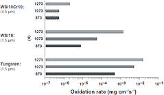
Figure 36. Oxidation rates of pure W, W–18Si and W10Si10Cr in 80 vol.% Ar + 20 vol.% O2 [177]. © The Royal Swedish Academy of Sciences. Reproduced by permission of IOP Publishing. All rights reserved.
Download figure:
Standard image High-resolution imageThe W–Si system features an about 100-fold decrease of the oxidation rate at 800 °C and an about ten-fold decrease at 1000 °C [177]. Despite the positive results, the stability of the samples was marginal. After already four hours of oxidation, the Si concentration used to build up an  layer oxide was exhausted. Then tungsten started to oxidize and continued across the large affected area, as can be seen in figure 37. Dark spots correspond to the area with an oxygen concentration of 63 at.% [177, 226].
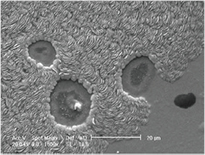
Figure 37. SEM surface image of 1 μm WSi13 oxidized at 800 °C for 4 h. The oxygen content of the dark area is about 62 at% [177]. © The Royal Swedish Academy of Sciences. Reproduced by permission of IOP Publishing. All rights reserved.
Download figure:
Standard image High-resolution image10.4. Thin films: ternary systems
In the following research was focused on ternary systems. Studies were undertaken with chromium (Cr) as a new alloying element. First results show further suppression of undesirable oxidation. The results for the W–Si–Cr system containing 10 wt.% of Si and 10 wt.% of Cr, respectively, are presented in figure 36. A noticeable decrease of the oxidation rate was observed: it dropped by more than an order of magnitude as compared with those measured on binary W–Si systems under identical conditions [177]. However, further studies revealed an increased brittleness of formed tungsten silicides caused by brittle binary W–Si intermetallic phases, which made the practical application of Si-containing smart alloys challenging [226, 227].
The research then moved towards to Si-free alloys. Due to its strong reactivity towards oxygen and stability of its oxide, titanium (Ti) was selected as the promising candidate for the novel smart alloy systems. Important results were achieved using ternary systems with titanium. Among the ternary systems produced by magnetron sputtering, the W–18Cr–2Ti and W–16Cr–9Ti systems demonstrated the slow oxidation, whereas the systems containing hafnium and tantalum, W–32Hf–2Ti and W–12Ta–2Ti showed poor adhesion to the substrate, and could therefore hardly be analyzed. Generally, the W–Cr–Ti systems benefit from the ability of Cr to form solid solutions with W, since both elements have bcc lattices. In addition, Ti contributes significantly to further reduction of the undesirable tungsten oxidation. The respective dependencies of the oxidation constants during the parabolic oxidation on the temperature are presented as Arrhenius plots in figure 38. It can be seen from figure 38 that the maximum suppression of oxidation was achieved for the W–Cr–Ti alloy containing 14–18 wt.% of Cr and about 2 wt.% of Ti.
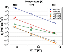
Figure 38. Arrhenius plot of parabolic oxidation rates of pure tungsten and different tungsten-based alloys [226]. Adapted from [226], Copyright 2009, with permission from Elsevier.
Download figure:
Standard image High-resolution image10.5. Yttrium as an active element in self-passivating tungsten alloys
Further investigations lead to the introduction of so-called active elements in the prospective alloys. Active elements even in small amounts may dramatically change the oxidation behavior. Yttrium is a well-known active element [228]. Adding of yttrium may cause a multitude of effects. Yttrium is known for its ability to limit the grain size growth, and to decrease the growth rate of an oxide scale [228]. This element is shown not to have cation transport—and, moreover, it suppresses the cation transport of the other elements, leading e.g. to a decrease of the growth stresses and improved adherence, when Y is present in small amounts [229, 230].
Y has a strong impact on oxide formation. The main processes involving yttrium are schematically shown in figure 38. Adding yttrium to an alloy system may:
- Introduce pegs at the interface between the alloy and the oxide scale [229, 231]. Pegs as shown in figure 39(a) act as a connection between the oxide and the alloy, which may increase the adherence of the oxide scale to the alloy system [229, 231, 232];
- Alter transport mechanisms through the oxides. Yttrium is usually segregated to the grain boundaries [230, 233] where the transport occurs. The oxide scale grows from the alloy, and yttrium acts as a vacation sink to suppress the formation of voids and pores at the interface [228, 229], as shown in figure 39(b).

Figure 39. Effects of yttrium on oxide formation: (1) formation of pegs stabilizing oxide scale; (2) segregation to grain boundaries and prevention of pores and (3) trapping of impurities and avoidance of nucleation sites.
Download figure:
Standard image High-resolution imageDue to its chemical reactivity, yttrium actively bonds the impurities—as depicted in figure 39(c)—preventing them from entering the oxide scale. The presence of impurities in the oxide may otherwise destabilize the oxide layer [228].
Introduction of yttrium can cause a strong effect on tungsten as well. The formation of yttrium nucleation sites at the grain boundaries of W (Y is not soluble in W) suppresses the crystal grain growth of tungsten and strengthen the grain boundaries. This, however, may lead to an increased brittleness of the tungsten-yttrium compound and to a respective increase of the ductile-to-brittle transition temperature (DBTT), according to recent findings [234].
10.6. Thin film alloys with yttrium
Smart alloy W–Cr–Y films were recently produced with magnetron sputtering. These smart alloys brought about a dramatic improvement in the oxidation behavior. A direct comparison of the oxidation of pure tungsten, one of the best W–Cr–Ti systems, and the new W–Cr–Y alloy is presented in figure 40. The new system demonstrates at least an order of magnitude better suppression of oxide formation during the isothermal oxidation in 80 vol.% + 20 vol.% O2 mixtures at 1 bar and 1000 °C.
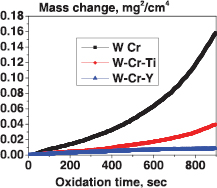
Figure 40. Oxidation of different smart alloys in 80 vol.% Ar + 20 vol.% O2 at a pressure of 1 bar and a temperature of 1000 °C.
Download figure:
Standard image High-resolution imageImages made after 10 min of oxidation are shown in figure 41. A much thinner and denser  oxide layer was found in case of the oxidation of the W–Cr–Y alloy. Pores, visible in figure 41(a) in the oxidized W–Cr–Ti system, are absent in the case of the W–Cr–Y system, as can be seen on figure 41(b). This demonstrates the positive effect of yttrium on smart alloys experimentally, as expected from research findings described above.
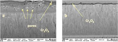
Figure 41. FIB cuts of (a) W–Cr–Ti and (b) W–Cr–Y smart alloys after 10 min of oxidation in 80 vol.% Ar + 20 vol.% O2 at 1000 °C.
Download figure:
Standard image High-resolution imageA series of investigations were carried out on specially prepared lamellae made from the thin film oxidized smart alloys. A lamella was cut using focused ion beam (FIB) and then thinned to a size of  μm and a thickness of 80 nm. A series of transmission electron microscope (TEM) measurements and energy-dispersive x-ray investigations (EDX) were undertaken on this lamella.
The main results are presented in the figure 42 as a distribution of W, Cr and Y along the alloy. No yttrium was found in the chromium oxide scale which is a striking result. Yttrium was detected to be distributed rather homogeneously in the bulk of the smart alloys. In addition, tiny yttrium precipitates with sizes of 10–30 nm, possibly acting as nucleation sites, are beginning to form as can be inferred from figure 42.

Figure 42. TEM images of the boundary between the protective oxide layers and the bulk of W–Cr–Y alloys. The nucleation site is shown in the red circle in the leftmost image.
Download figure:
Standard image High-resolution imageThe systematic scan of the elemental fractions of alloying elements was performed for the W–Cr–Y alloy system. A series of thin film alloys featuring different fractions of yttrium and chromium were produced and oxidized isothermally under identical conditions. In the initial scan, the fraction of chromium was fixed at a level of 12 wt.%. This was the fraction at which the suppression of oxidation mentioned above was observed for the first time. The yttrium fraction was varied over the range of 0–1.0 wt.%. The results of this study are shown in figure 43(a). The minimum in the oxidation rate was found at an yttrium fraction of 0.6 wt.%. With this fraction fixed, the variation of the chromium concentration was performed. The results of the chromium elemental scans are shown in figure 43(b). The optimum elemental composition of W–Cr–Y system was found to be: 12 wt.% Cr, 0.6 wt.% Y and tungsten constituting the rest. This composition was later used for manufacturing of the bulk smart alloy systems.
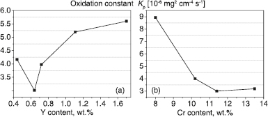
Figure 43. Elemental scans of the alloying elements in the W–Cr–Y self-passivating alloy. Oxidation constants as function of (a) yttrium content with Cr fixed at 12 wt.% and (b) chromium content with fixed Y content of 0.4 wt.%. Please note that the origin is suppressed at both x and y axes.
Download figure:
Standard image High-resolution image10.7. Bulk smart alloy systems
Manufacturing of bulk samples represents a crucially important part of the entire research activities on smart alloys. Ensuring the homogeneity, low porosity and purity of the manufactured samples represents an ultimate challenge. Several fabrication strategies have been studied so far. Most of the techniques used in the production of bulk smart alloys include mechanical alloying (MA) of the elemental powders of tungsten and alloying elements [235–243], followed by either by sintering [238] or by hot isostatic pressing (HIP) [235–237].
Bulk W–Cr– alloys were manufactured by mechanical alloying of W, Cr and
  powders according to [239–243]. The MA resulted in ultra-fine grain alloyed powders with the grain size of 30–50 nm. Afterwards, a five-hour sintering step at 1700 °C was applied. The resulting alloys contained 3 wt.% of
  and equal fractions of tungsten and chromium in one case (
 with 3 wt.%) and with a dominant atomic fraction of 70 wt.% W in another. The densification to 98% theoretical density was attained with both types of sample via this manufacturing route. The analyses after sintering revealed the existence of the large
  particles with sizes spread between 3 and 12 μm, and an average particle size of about 5 μm. Series of non-isothermal oxidation tests were performed on manufactured samples and all of them showed a reduction of the oxidation rates. Non-isothermal tests were performed in the range 20–1200 °C with a temperature rate of 10 °C per minute. The oxidation rates were found to be strongly dependent on the Cr content, and the best results were achieved for the system
  . The corresponding mass gain as a function of time is presented in figure 44. At temperatures above 1000 °C, a transition in the oxide scale formation mechanism was observed: the ternary oxide
  was formed instead of
  . In addition, yttrium was found to form the ternary oxide
  at temperatures above 800 °C [238]. According to the phase diagram,
  melts at 1400 °C and forms a dense eutectic at 1155 °C. Such an eutectic possibly assisted in establishing a pore-free continuous oxide scale. Moreover, the liquid phase of molten
  imposes a kind of self-healing mechanism to the oxide scale, promoting the formation of a pore-free interface with excellent adhesion. Certainly, high temperature oxidations are very important, and need to be subject to continued investigation in future to allow better understanding of the processes and mechanisms involved.
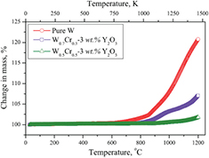
Figure 44. Change in mass against temperature at a heating rate of 10 °C min−1 for pure W and 
 (x = 0.3 and 0.5) composite samples [238]. © The Minerals, Metals & Materials Society and ASM International 2015. With permission of Springer.
Download figure:
Standard image High-resolution imageAnother strategy was pursued with W–Cr–Si, W–Cr–Ti, and lately with W–Cr–Y ternary systems. The procedure comprised mechanical alloying followed by HIP of the alloyed powders. MA was performed in the planetary milling facility using tungsten carbide jars and balls. Different milling times, milling rotation speeds and the ball-to-powder ratio (BPR) were investigated. These parameters were found to influence the grain size, homogeneity of the powder and the thermo-mechanical properties of the resulting alloy systems. It could be shown that during the MA, in case of W–Cr–Ti powders, the smaller particles became fused to the larger ones. There seems to exist a balance between the rate of fracturing and the rate of fusing, driving the smallest and the largest particles towards the intermediate size [235]. The understanding of the balance parameters remains, however, still at an empirical level.
Following the outcome of studies on W–Cr–Si thin films, which show an unavoidable formation of the disadvantageously brittle silicides of both W and Cr [244], the production of bulk samples was re-focused to W–Cr–Ti systems. The bulk alloy W–12Cr–2.5Ti was produced using 40 h of MA of the elementary powders, BPR 5:1, glass encapsulation and subsequent HIPing at 1300 °C at a pressure of 150 MPa for one hour. Isothermal oxidations in a mixture of 80 vol.% Ar + 20 vol.% O2 at temperatures between 800 and 1000 °C were carried out. The oxidation rates of pure tungsten, the thin-film W–Cr–Ti system with the similar composition of alloying elements, and that of bulk systems are plotted on figure 45. A significant decrease of the oxidation rates of the W–Cr–Ti alloy as compared to those of pure tungsten is clearly visible in these measurements. At the same time, direct comparison of the oxidation rates of the thin film and bulk systems of similar elemental composition reveals only moderate deviations at the same temperature.
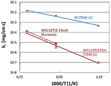
Figure 45. Arrhenius plot of the linear oxidation rates for pure W measured by TGA [235], bulk W12Cr2.5Ti alloy measured by furnace exposure, and thin film W14Cr2Ti alloy measured by TGA [235]. © The Royal Swedish Academy of Sciences. Reproduced by permission of IOP Publishing. All rights reserved.
Download figure:
Standard image High-resolution imageFollowing the promising results obtained with the thin film yttrium-containing alloys described earlier, and taking into account advantages of yttrium in oxide formation, first efforts to manufacture W–Cr–Y bulk systems were made. The first bulk yttrium-containing smart alloys were produced following the powder-metallurgical route including HIPing of mechanically alloyed elemental powders, as described above. The MA was performed for 50 h, followed by an encapsulation in glass. The HIPing took place at the pressure of 150 MPa and a temperature of 1250 °C for 1 h. The manufactured samples were homogeneous in structure, showing a fine nano-grain structure.
The average grain size of alloying elements was approx. 90 nm, as can be seen from the figure 46. The small dark spots in the cross-sectional view seen in this image are then particles of yttrium oxide, as detected with energy-dispersive x-ray analysis (EDX). These findings are in agreement with the results of TEM investigations on a lamella of the smart alloy manufactured using magnetron sputtering, as described above—see figure 42.
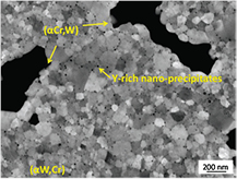
Figure 46. SEM image of a mechanically alloyed W–Cr–Y powder [237]. Reproduced from [237]. CC BY-NC-ND 4.0.
Download figure:
Standard image High-resolution imageThe observed nano-precipitates may act as nucleation sites and can limit a grain growth [228]. In turn, a homogeneous distribution of yttrium on the atomic scale, as observed in thin film samples, was not detected in the bulk powder-metallurgical system. At the same time, good passivation of the bulk smart alloy samples was measured and reported in [237]. Therefore, it remains to determine the main mechanism of yttrium influencing the oxidation behavior: the directed oxidation via nucleation sites of yttrium oxide, or the cumulative effect of yttrium particles homogeneously distributed in the bulk of the alloy as detected in the thin film smart alloy sample—see figure 42.
High Vickers hardnesses of  were measured for the smart alloys produced. This is to be compared with
  for pure tungsten (see e.g. [245]). By adding a temperature treatment step at 1600 °C it was possible to reduce the hardness to
  —however, at the expense of the structural integrity of the alloy system and of a larger grain size of about 1 μm.
Bulk W–Cr–Ti and W–Cr–Y samples exhibited a high DBTT. Samples were tested to be brittle up to 900 °C. There are a number of reasons for such a high brittleness measured during the experiments. A high concentration of interstitials, particularly oxygen, segregating to the grain boundaries may lead to a weakening of the grain boundary strength. The observed extremely small grain size (figure 46) will lead to the formation of a large total grain boundary area. Besides, alloying with a relatively large amount of Cr results in embrittlement, if no cold working is performed to increase the amount of edge dislocations, which are known to reduce the DBTT, as mentioned in [237, 246].
10.8. Smart alloys under plasma impact
While the production of bulk samples from the promising W–Cr–Y alloy has just started, the production of bulk W–Cr–Ti alloy systems is a rather established procedure [235–237]. Therefore, the W–Cr–Ti alloy systems were first tested for plasma compatibility and exposed in the linear plasma device PSI-2. The first direct comparative test of pure tungsten and smart alloys under identical plasma conditions was performed. W–Cr–Ti alloys were exposed simultaneously with tungsten samples to a stationary deuterium plasma in linear plasma device PSI-2. The exposure of smart alloys and tungsten samples is shown in figure 47.
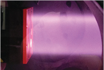
Figure 47. Exposure of smart W–Cr–Y alloys and tungsten samples in a steady-state deuterium plasma of the linear device PSI-2. The samples are visible as bright areas, arranged along a circle on the sample holder. Heating power is provided by the plasma.
Download figure:
Standard image High-resolution imageThe temperature of the samples was about 700 °C, the energy of impinging ions was 210 eV, corresponding to the conditions expected at the first wall of DEMO [247]. The accumulated fluence was  m−2. Elemental composition and surface morphology of the samples were analyzed before and after exposure. The weight loss of pure tungsten samples after exposure was
  –1150 μg, resulting in a sputtering yield of
  –
– . The measured weight loss of sputtered smart alloy sample
  corresponds very well to that of pure tungsten, providing experimental evidence of good resistance of smart alloys to plasma sputtering. The direct measurement of sputtered material during plasma exposure was performed by means of FIB craters with scales as shown in figure 48. Tungsten samples lost 500 nm through sputtering by D ions, whereas the smart alloy lost about 700 nm, outlining moderate differences in sputtering rates between the two materials.

Figure 48. Focused ion beam (FIB) cuts with pre-prepared depth scales of a pure tungsten sample (a) before and (b) after exposure in PSI-2. Corresponding FIB cuts were produced of a smart alloy W–Cr–Ti sample (c) before and (d) after exposure in PSI-2. The depth scale step is 1 μm. Differences in height are shown at the arrows and provide a direct measure of the sputtered material thickness.
Download figure:
Standard image High-resolution image10.9. Outlook for future studies
Current studies have outlined the significant progress in physics understanding, research and development of self-passivating tungsten smart alloys for future fusion power plants. At the same time, there are a number of critical topics to be addressed in future research.
Tests of smart alloy systems in humid environments need to be peformed. The current knowledge on oxidation rates is mostly based on studying pure tungsten samples in the flow of humid air or steam. The predicted intensive evaporation of tungsten oxides in the form of an aerosol is quite worrying [248–250]. It should be mentioned, however, that the conditions of reported experiments were rather extreme, and correspond to a directed intensive stream of steam or humid air. Therefore, the results cannot be directly applied for evaluation of plasma-facing components during LOCA with (humid) air ingress. Therefore, dedicated comparative studies of oxidation of pure samples and smart alloys in humid atmosphere at atmospheric pressures and at relevant humidities need to be performed.
Oxidation tests at elevated temperatures in the order of 1200 °C need to be carried out, addressing the upper estimate of the temperatures of plasma-facing components after an accident. Here, significant evaporation rates of chromium are expected. The corresponding effect of chromium depletion on the self-passivating properties needs to be evaluated.
Plasma tests of the smart alloy systems under fusion plant conditions are of crucial importance. Sputtering of the smart alloys, the development of specific surface morphologies and the long-term tritium retention in smart alloys are the critical questions to be addressed during these tests.
At the same time, there are several issues to be addressed in the future. The formation of an enhanced surface morphology including bubbles, blisters and fuzz structures during plasma exposure, and the response of new smart alloy systems to the transient plasma events are to be investigated. Plasma–surface interactions with neutron-damaged samples need to be studied. The corresponding experiments are under preparation.
The ultimate goal of plasma and oxidation tests is the qualification of new smart tungsten alloys under the full range of conditions expected both during normal operation and during an accident scenario. New advanced material concepts, like tungsten fiber-reinforced composites (Wf /W) are being developed to increase the robustness of tungsten, see section 7 and e.g. [251]. The combination of self-passivating smart alloys with a fiber-reinforced composite needs to be evaluated and tested both under plasma exposure and in accident conditions.
The ongoing research clearly indicates the severity of the problem of combined good oxidation resistance, tolerable plasma performance and acceptable thermo-mechanical properties. More physics understanding is required for the oxidation process, its dynamics and responsible mechanisms. Achieving a sufficiently low (apparent) brittleness and an acceptable concentration of chromium represent clear challenges, demanding more detailed studies.
11. Permeation barrier layers
11.1. Review on hydrogen isotope permeation barrier layers
Since the beginning of the last century, hydrogen diffusion and permeation through metals have been investigated [252–256]. The study of hydrogen diffusion in non-metals started later in the 1960s. The first publications were more basic research related, and the aim was to understand the permeation through non-metals [257, 258].
Already in the 1970s, first-wall materials, especially steels, were investigated regarding the hydrogen isotope permeation [259–261]. The aim of these studies was mainly the predictability of the wall loading, since the loss of fuel has a strong influence on the operation of fusion reactors. Furthermore, the influence of hydrogen ions on the wall materials was studied, e.g. the occurrence of surface cracking [261, 262]. The environmental safety issue regarding loss of radioactive tritium to the environment was a secondary aspect. Due to the reason that fusion reactor wall components were mainly made from stainless steel at that time, iron and different steel grades were investigated, e.g. 309S and A-286 [263]. The permeation measurements were mainly performed by deuterium or tritium ion-driven permeation setups. With every new development of first wall materials, e.g. graphite, beryllium and tungsten, the hydrogen permeation measurements were extended and enhanced to these materials [264–272].
Since the 1970s [273], using metal oxide layers, e.g.  , as hydrogen permeation barriers were discussed and also investigated in other research topics, e.g. for high-temperature gas-cooled fission reactors [274, 275]. Furthermore, it was noticed that the natural oxide layers on steels produced by preoxidation have an influence on the hydrogen permeation [276, 277]. In addition to the high hydrogen permeation reduction, the thermal stability is a major advantage of oxide layers.
Next to metal oxide layers, nitrides, e.g. TiN, and carbides, e.g. SiC, were investigated regarding the viability as a hydrogen permeation barrier. A recent and detailed overview can be found by Causey et al [272].
There are numerous reports relating to the promising hydrogen permeation barrier  for fusion applications [278–282]. The permeation reduction factor for an
  layer on steel varies between 102–104 [272, 282]. Due to better compatibility with liquid lithium–lead, higher thermal stability and better neutron activation behavior of erbium compared to aluminum,
  was investigated in the last years [283–286]. The permeation reduction factor of
  is comparable to the reduction factor of
  [283, 284].
The development of hydrogen permeation barriers is also important in other research fields. The loss of hydrogen from tanks in fuel-cell-powered cars has to be prevented, also as a safety aspect [287]. Another example is the prevention of hydrogen permeation into vacuum insulation tubes in solarthermal power plants [66]. The requirements on hydrogen permeation barriers in other research fields are different compared to the application in fusion reactors. Nevertheless, an effective hydrogen permeation barrier can be applied for various applications.
11.2. Permeation physics
11.2.1. Basis equations.
The hydrogen isotope (protium, deuterium and tritium) permeation through a single-layer material can be expressed in principle by a multiplication of two predominant processes: solution and diffusion [259]. When hydrogen atoms form a solid solution in the material, the hydrogen solubility S (mol m−3) is given by Sieverts' law:

where KS is the equilibrium solution constant (reciprocal number of Sieverts' constant, mol m−3 Pa−0.5) and p is the hydrogen pressure (Pa). The hydrogen diffusivity D (m2 s−1) is a thermally activated process expressed by the Arrhenius rate equation:
where ED (J mol−1) is the activation energy of diffusion, R (8.314 J K−1 mol−1) is the gas constant, and T (K) is the temperature. The hydrogen permeation flux per unit area at steady-state J (mol m−2 s−1) can be described by the first Fick's law:
where c (mol m−3) is the hydrogen concentration at position x (m). Given a sufficiently lower concentration at the outlet side than that at the inlet side of the material, J through the material of d in thickness is expressed with the product of the equations (10) and (12):
where  is the permeability P (mol m−1 s−1 Pa−0.5) as the intrinsic parameter of the permeation. P is also a thermally activated process expressed as:
where EP (J mol−1) is the activation energy of permeation calculated by the sum of ED and the enthalpy difference between hydrogen in gas phase and that in the material.
It should be noted that the simplest case of the permeation, where the rate-limiting process is the diffusion of hydrogen atoms through the solid, can satisfy the equations described above. When the permeation rate is limited by a hydrogen molecule process as typified by surface reactions such as absorption, dissociation, recombination and desorption, the exponent of the driving pressure p will increase to unity (n = 1). The surface contribution would be derived from a large surface roughness, chemical reactions with the material or impurities such as carbon [285]. When the diffusion and surface limited regimes are comparable, the exponent of the driving pressure will indicate between 0.5 and 1.
The permeation barrier performance of a coated sample is often evaluated using a permeation reduction factor (PRF): a ratio of P or J of an uncoated sample to that of a coated one. However, it is also important to pay attention to absolute values of the permeability and permeation flux, since the PRF varies depending on not only the barrier coating but the substrate material: e.g. austenitic and ferritic steels.
11.2.2. Influence factors in permeation.
For the development of a TPB for fusion reactors, the clarification and control of dominant factors influencing hydrogen permeation under reactor operational conditions are essential. The most basic factor would be types of chemical bonds derived from different electronic structures. Metals, except for a few elements such as tungsten and gold, generally have higher permeability than ceramics because metallic bonds exert much lower solubility and much higher diffusivity than ionic and covalent bonds. That is why ceramics have been employed as TPB candidate materials. However, the number of studies focused on the discussion of hydrogen permeation behaviours through ceramics is quite small in comparison with metals. Here we compile investigations on hydrogen permeation mechanism in ceramic bulks and thin films.
The major factors influencing hydrogen permeation through ceramic materials may include composition, crystal structure, phase and defect. As mentioned previously, oxides and carbides are representative compositions for TPB coatings. Therefore, the dominant parameter influenced by composition is hydrogen's interaction with oxygen or carbon as well as metal or non-metal elements. In fact, Yao et al reported that C–H and O–H bonds made an important contribution to permeation barrier efficiency from the analysis using secondary ion mass spectroscopy (SIMS) and infrared spectroscopy (IR) for TiC and  coatings [288]. Regarding the influence of the crystal phase, tritium diffusivity and deuterium solubility of several types of α-SiC and β-SiC was investigated by Causey et al [289]. The results indicate that the phase makes smaller effects in permeation than other factors such as purity and crystallinity. Chikada et al performed deuterium permeation experiments for amorphous SiC coatings deposited on steels, indicating the amorphous structure also exhibited an efficient permeation reduction [285]. That is probably because Si and C chemically bind to deuterium, and the bindings block the migration of other deuterium atoms. In the case of
  , Levchuk et al showed deuterium permeation through amorphous and γ-
 mixture coatings and an α-
 coating [282]. The mixture coating showed higher permeability than the α-
 one due to a higher hydrogen diffusivity in the amorphous structure than that in the crystallized structure. These results clearly indicate that both chemical composition and crystallinity strongly influence hydrogen permeation in the coatings.
The defect in a crystal lattice might be one of the most important factors in permeation through permeation barriers. In particular, grain boundaries, which are a kind of aggregation of point defects, have a clear influence on permeation behaviours. Zakharov et al showed that polycrystalline W and Mo tubes had somewhat higher permeabilities than those of single crystal in the temperature range of 400–1200 °C [290]. In the case of ceramics, Chikada et al investigated deuterium permeation through  coatings fabricated by filtered vacuum arc deposition [291]. The results of permeation experiments and microstructure observation indicated that the deuterium permeation was dominated by grain boundary diffusion in the temperature range of 500–700 °C. This suggestion was verified by deuterium concentration in the coatings measured using nuclear reaction analysis (NRA) and nano-scale SIMS [292]. On the other hand, the hydrogen permeation through sintered
  tubes tested at higher temperatures (1200–1450 °C) showed that the dominant transport process was lattice diffusion [293, 294]. Therefore, the dominant transport process, lattice diffusion or grain boundary diffusion, is dependent on the temperature range and the grain size. One criterion to determine the dominant process is to estimate the activation energy of permeation EP in equation (14), since in principle the grain boundary diffusion has lower values of EP.
11.3. Application to fusion reactors
As discussed above, it is important to select appropriate materials and fabrication techniques satisfying required properties depending on components and reactor conditions: temperature, contact materials, irradiation, etc. For plasma-facing components, a high thermal shock resistance as well as an effective permeation reduction should be required. The fabrication process would be rather flexible, because small-scale processes can be applied to components such as the divertor tiles. In addition, a favorable feature is that high-temperature fabrication (>1000 °C) would be acceptable. On the other hand, the application to the blanket chassis and the tritium recovery system seems to be more challenging. Except for SiC/SiC composites, the present candidates for the structural material of a fusion reactor are metal-based materials: reducing activation ferritic/martensitic (RAFM) steels including oxides dispersion-strengthened (ODS) steels and vanadium alloys; the operation temperature limit is less than 700 °C. The complex geometry and large surface area of the components also limits options for the fabrication process. Moreover, chemical reactions and corrosion by the blanket materials, in particular tritium breeders ( ,
,  , Li–Pb) and coolants (He, H2, water, Li–Pb), must be controlled for a long-life operation. The representative results of hydrogen isotope permeation experiments for several ceramic coatings on steel substrates are presented in figure 49. Currently PRFs of more than 103 have been achieved by
  ,
,  , SiC, and TiN + TiC coatings fabricated in vacuum chambers via plasma processes [117, 285], [288, 295–297] or by a liquid phase method in a laboratory-scale system [298, 299]. It should be noted that both-side-coated samples and multiple coatings indicated excellent permeation reduction, which suggests hydrogen permeation can be suppressed by multiple steps of solution and diffusion [295]. Regarding the performance as TPBs, the coatings will satisfy the requirement of most DEMO blankets; however, to establish manufacturing practical components and an assessment of compatibility with reactor materials has to be developed. From that perspective, the development of a corrosion protection by the multi-layer structure [286] becomes a more important challenge. In addition, a self-healing function should be effective to enhance the reliability as the multi-functional coatings exposed to the severe environment.
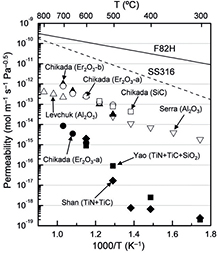
Figure 49. Arrhenius plots of hydrogen isotope permeability of steels and coated samples [117, 285, 288, 295–299].
Download figure:
Standard image High-resolution image12. Functionally graded materials for fusion applications
The concept of FGMs was proposed in 1984 by material scientists in the Sendai area in Japan as a means of preparing thermal barrier material [300]. FGMs are essentially two-phase particulate composites synthesized in such a way that the volume fractions of the constituents vary continuously in the thickness direction to give a predetermined composition profile [301]. Even if the gradation of the material ingredients is limited to a specific location in the material such as the interface, a joint, or a surface, the material can be considered to be an FGM because it incorporates the FGM concept [302]. Pores are also important material ingredients of FGM: their gradual changes can impart properties of materials. The material ingredients can change in both continuous and discontinuous ways, the latter also being named stepwise gradation. One obvious and central advantage of FGM is its combination of ordinarily incompatible functions, i.e. the technology of FGMs realizes innovative and multiple functions that cannot be achieved with conventional homogeneous materials. The composition of each material ingredient can be designed artificially.
The earliest study on W/Cu FGM was performed by M.M. Gasik in the 1990s for the application of upper divertor plates of the international experimental thermonuclear reactor (ITER) [303]. The micromechanical model, the theoretical analysis of the thermal elasto-plastic behavior of the W/Cu FGM divertor plate with temperature-dependent properties has been shown in [304]. The reduction of thermal stresses or plastic strain by application of W/Cu FGM in the joints of W and Cu has been proved by finite element modelling (FEM) [305]. Due to the large difference in melting and sintering temperatures of the composed materials, traditional sintering is not suitable for the fabrication of FGM, such as W/Cu FGM. A new sintering and infiltration technique was approved by Y. Itoh in 1996. The main fabrication process comprises fabricating a tungsten skeleton with graded pores first, then infiltrating molten copper into the graded pores [306] or making a graded tungsten skeleton using electrochemical processing, followed by infiltration with molten copper [307]. It is clear that the infiltration method usually consists of two steps: formation of a gradient tungsten skeleton and infiltration of molten copper. The fine gradation range, dense material at moderate cost and several mm thickness of FGM could be realized, but the large scale feasibility is limited by the first step, and it is almost impossible to obtain a dense pure W layer. Another novel sintering method combining ultra-high pressure and resistance sintering was also used successfully in the preparation of W/Cu FGM [308–311] and W/steel (Fe) FGM [312, 313]. The advantages of RSUHP (resistance sintering at ultra-high pressures) are the full gradation level of FGM, low cost and efficient fabrication, while the drawback of no vacuum cannot be ignored and a large scale sample is also not feasible. Dense W–Cu–W multilayers with a limited thickness deposited on Fe substrate are obtained by magnetron sputtering [314]. Other sintering methods, such as laser sintering and microwave sintering, for fabrication of W/Cu FGM have been attempted successfully, and the main drawback of laser sintering is that an assembly of a graded structure is only possible when the starting point is at the Cu side [315, 316]. Plasma spraying is another widely adopted method, which includes atmospheric plasma spraying (APS) [317] and vacuum plasma spraying (VPS) [312, 318]. APS is increasingly being replaced by VPS due to its oxidation problem, in which the oxygen content of the whole coating is higher than 1 wt.% [317].
12.1. Assessment and design of FGM
12.1.1. W/Cu FGM.
Two kinds of actively water cooled W/Cu FGM based HHFC mock ups have been designed, borrowing ideas from the W–Cu joint concepts, viz. the monoblock concept and flat tile concept, which were selected by ITER. For W–Cu joint mock-ups, it has been demonstrated that the monoblock design has better performance than the flat tile design under high heat flux loads. The W/Cu FGM monoblock was designed for examining and comparing the temperature distribution and thermal stress under high heat flux to that of W/Cu FGM flat tile mock-up. A geometric analysis of the models is shown in figure 50. Model 1 is a design of monoblock concept (figure 50(a)). The cooling channel is located in the middle of the W/Cu FGM. Distance from bottom of cooling channel to bottom of mock-up is 3 mm. Model 2 is a flat tile concept design (figure 50(b)). The HHFC is formed by three sections of different materials: at the top, the W armor faces the high heat load and radiation; at the bottom, the Cu substrate removes heat by means of water flowing through the cooling channel; in the middle, the graded layers between the W armor and the Cu substrate mitigate the thermal stress. The volume fraction of W in the graded layers is expressed by the following equation:

in which VW represents the volume fraction of the W phase in the FGM, p is known as the gradient index, h is the thickness of the FGM, x is the distance to the pure W surface. Here x = 0 corresponds to pure W and x = h to pure Cu. The different gradient architectures used to join the Cu and W and the thermo-mechanical properties of Cu, W and FGM are listed in tables of [319] and [320].

Figure 50. Geometry of the W–Cu joint mock up with different interlayers, (a) monoblock design and (b) flat type design.
Download figure:
Standard image High-resolution imageThe operation condition is modeled and analyzed according to the design of ITER. A steady-state heat load of 5 MW m−2 is supposed to load on the top of the W armor. Water is flowing through the channel in the Cu at 160 °C, 4 MPa and 10 ms−1. Stress and strain fields are obtained from the resulting temperature profile.
The temperature gradient and the von Mises stress gradient distribution of W/Cu FGM based HHFC with the monoblock type and the flat tile type have been demonstrated. The maximum temperature occurs on the W surface exposed to the heat and decreases towards the channel. For flat tile type, the maximum temperature is more controlled by number and thickness of graded layers. Increasing the thickness of graded layers from 1 to 3 mm raises the maximum temperature from 558 K to 594 K. The maximum temperature for the monoblock type is 593.7 K, nearly the same as for the flat tile type. The stresses in the interlayers tend to be compressive under operational conditions. The stress is more uniformly distributed throughout the graded interlayer of monoblock type, as compared with the sharper stress gradient in the flat type. Clearly, the optimum stress distribution for the operation stresses in flat type exists for the three layers in thickness of 3 mm. It also shows the smallest plastic strain. The von Mises stress,  , and equivalent plastic strain of monoblock type and flat type are nearly the same [319].
12.1.2. W/EUROFER97 FGM.
The potential of functionally graded W/EUROFER97 joints has been examined using the finite element method in several publications [46, 321]. Here it shall be illustrated for the helium-cooled divertor design developed at KIT [322]. Elasto-plastic and elasto-viscoplastic simulations [323] have been performed under variation of the layer thickness, layer orientation and transition function. The resulting stresses and strains were used as basis for the subsequent lifetime estimation. Cycling of temperature comes along with the design of a tokamak reactor, and yields failure of the joint due to fatigue and creep. For the calculation of the number of allowable cycles, fatigue as well as creep damage are considered in the evaluation for the EUROFER97 part. Creep is neglected for the tungsten part. The lifetime of the joining layer could not be assessed due to the lack of experimental data. However, the quantified improvement in the lifetimes of the joined parts when varying the parameters of the joints also applies for the joining layer, at least qualitatively. The materials parameters, boundary conditions, governing equations and details used in the FEM model can be found in [46] and [323]. The model geometry is a tube with an inner diameter of 14 mm and an outer diameter of 15 mm.
A cooldown from 800 °C to 0 °C and subsequent thermal cycling between 0 °C and 650 °C for 100 cycles results in the maximum equivalent inelastic strain shown in figure 51. While very high deformations can be expected in a concentrated region at the outer side of the joint for thin interlayer thicknesses, the strain is far less, and distributed over a bigger area for thick graded interlayers.
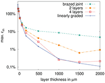
Figure 51. Maximum equivalent inelastic strain for a single, double, quadruple layered and linear graded joint between W and EUROFER97.
Download figure:
Standard image High-resolution imageThe result of the fatigue-lifetime estimation for the EUROFER97 region is shown in figure 52. The results for the tungsten region can be found in [323]. The Basquin–Manson–Coffin relationship between the equivalent strain range  and the number of allowed cycles Nd
are proposed as design criteria in [324]. Thereby
and the number of allowed cycles Nd
are proposed as design criteria in [324]. Thereby  is calculated according to the RCC-MR code. While a brazed joint only allows a cycling over several hundred cycles according to these design criteria, several ten thousand cycles are allowed when a linear joint transition is considered.
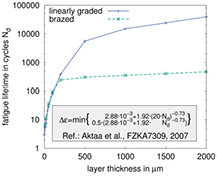
Figure 52. Lifetime considering fatigue over the layer thickness.
Download figure:
Standard image High-resolution imageThe calculated lifetime considering creep is presented in figure 53. It contains a curve for EUROFER97 based on the design criteria proposed in [324], and two curves for EUROFER97 and ODS-EUROFER, respectively, based on the time to rupture curves [325]. A detailed description of the parameter extrapolation for ODS-EUROFER97 can be found in [323]. The lifetime is calculated through a linear damage accumulation for each time step of the FEM simulation. Thereby the integration point with the shortest lifetime is considered.
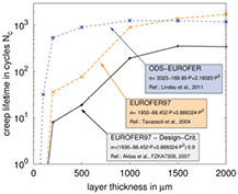
Figure 53. Lifetime considering creep over the layer thickness.
Download figure:
Standard image High-resolution imageLooking at the number of cycles allowed, a clear positive correlation to the interlayer thickness is again noticeable. Nevertheless, a saturation level is reached at about 1 mm layer thickness. At higher thicknesses the maximum stresses in the EUROFER97 section are not any longer at the interface. Instead, bending stresses caused by the radius difference become important. Only much thicker layers (>5 mm) would further reduce the stresses. A second insight is that the oxide dispersed strengthened version of the EUROFER97 steel does not substantially increase the lifetime. The explanation for this phenomenon is that the creep of EUROFER97 is strain-controlled, rather than stress-controlled.
The FE simulations performed show that a functionally graded joint between tungsten and EUROFER97 can drastically decrease the thermal mismatch stresses and strains occurring in the divertor component considered, and thus improve its failure behavior during thermal cycling. However, the functionally graded layer shall have a sufficient thickness that has to be taken into account in the selection of fabrication methods.
Smoothing the gradation on the EUROFER97 side or beveling of the linear graded layer reduces the maximum equivalent inelastic strain up to a factor of two (shown in [46]). However, since the realization of both is fairly challenging this gain might not justify the development efforts required. Simulations on W/EUROFER97 FGM are also performed for its application as erosion protective coating for First Wall component using the finite element code ABAQUS. The residual stresses induced in the whole component during the fabrication phase and subsequent operation phase are calculated for determining thicknesses of the W/EUROFER97 FG-layer.
In the simulations of the first cooling down phase, the behaviour of all materials is considered to isotropic, linear elastic and perfectly plastic. For the simulations of the operation phase, the Norton power law of creep is taken into account. The 2D sketch mesh, generalized plane strain elements, as well as boundary condition are introduced in detail in Ref. [326]. The model is loaded by a homogeneous temperature field that varies over time, simulating a cooling down after the hot manufacturing process. After this phase the temperature alternates between 20 °C and 600 °C with a dwell time of 24 h at 600 °C, which corresponds to an operation cycle of the fusion reactor.
As shown in figure 54(a), taking the model with a 0.5 mm thick FG-layer as an example, the maximum von Mises stress that occurs in W, which is limited by the yield stress, gradually reduces from W to EUROFER97. In addition, the stress in W is compressive, while tensile stresses appear in EUROFER97. The compressive stresses in W are not significantly destructive, even though they are almost equal to the yield stress of W. This means that W is supposed to deform plastically during the cooling phase. In contrast, the tensile stresses in EUROFER97 are lower than its yield stresses. Plotting the maximum of von Mises stress and equivalent plastic strain over the thickness of FG-layer—see figure 54(b)—the maximum equivalent plastic strain in W obviously decreases with increasing thickness of the FG-layer, while that in EUROFER97 is equal to 0 for all modelled thicknesses of the FG-layer. The maximum von Mises stress in EUROFER97 is limited by the yield stress for 4 mm thick FG-layer, which means that the thickness should be less than 4 mm to avoid plastic deformation of EUROFER97.
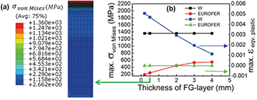
Figure 54. (a) von Mises stress distribution of the model with 0.5 mm thick FG-layer, and (b) maximum von Mises stress and maximum equivalent plastic strain appearing in Wand EUROFER97 versus thickness of FG-layer.
Download figure:
Standard image High-resolution imageFigure 55(a) illustrates the variation of the equivalent creep strain after 365 cycles (one year) with a hold time of 365 × 24 h over all FG-layer thicknesses. The equivalent creep strain decreases drastically with increasing thickness of FG-layer. It is worth mentioning that the equivalent creep strain is less than 10−5 after 365 thermal cycles when the thickness of FG-layer is thicker than 1.2 mm, and it is almost the same for the model with a 1.5 mm thick FG-layer. As it can be seen in figure 55(b), the maximum equivalent creep strain of all investigated thicknesses increases over thermal cycles, but the thicker the FG-layer, the smaller the creep strain. Particularly for FG-layers thicker than 0.7 mm, a shakedown is observed. In addition, the maximum equivalent creep strain becomes small and constant over the number of cycles for FG-layer thicker than 1.0 mm. The maximum equivalent creep strain is less than 10−5 even after 600 thermal cycles when the thickness of FG-layer is 1.2 mm. The allowable number of cycles in EUROFER97 seems to increase proportionally for 1.2 and 1.5 mm thick FG-layers after creep damage accumulation of 600 cycles. As shown in figure 56, the allowable number of cycles Ncr increases linearly to the thicknesses of the FG-layer when it is thinner than 1.0 mm, while it increases similarly over one order of magnitude for the models with 1.2 and 1.5 mm thick FG-layers. The lifetimes improve remarkably with increasing thickness of the FG-layer.
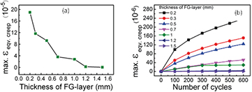
Figure 55. (a) Maximum of equivalent creep strain after 365 cycles for the FE model as a function of the FG-layer, and (b) Maximum of equivalent creep strain over number of cycles for all investigated thicknesses.
Download figure:
Standard image High-resolution image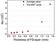
Figure 56. Allowable number of cycles for EUROFER97.
Download figure:
Standard image High-resolution image12.2. W/Cu FGMs
W/Cu FGMs are developed not only to combine the advantages of the low erosion rate of tungsten by the plasma with the advantages of the high heat conduction of Cu, but also to release residual stress due to large mismatch of coefficient of thermal expansion (CTE). The fabrication methods used in the authors' group consist of resistance sintering under ultra-high pressure (RSUHP), infiltration-welding and air plasma spraying (APS).
12.2.1. Resistance sintering under ultra-high pressure.
A novel one step method, called 'resistance sintering under ultra-high pressure (RSUHP)', has been developed to fabricate W/Cu FGM without the addition of any sintering additive. W and Cu powders were mixed and milled with different compositions and then stacked layer by layer in a steel mold to form a green compact. The W/Cu FGM green compact was placed in the pressure vessel; the details of the setup can be found in [308]. First, the pressure was mechanically cubic isostatic loaded on the W/Cu FGM green compact, then an alternating current (AC) was applied to the sample, thus heating and sintering the FGM by Joule heating. Sintering parameters should be suitable; investigations on sintering parameters and sintering mechanism are introduced in [309, 327, 328].
Figure 57(a) shows the picture of the fabricated W/Cu FGM mock up by RSUHP. Figure 57(b) illustrates the backscattering image of the cross section of the overall five-layered W/Cu FGM with p = 1, in which the W component is white and the Cu is black colored. A good graded composition transition is found. The interfaces between layers are clear. This reveals that there has been no obvious composition migration during the short sintering time. The relative density of pure W layer was more than 97%. The hardness of the pure W layer was 780 HV, which is much higher than pure conventional sintered W (about 350 HV). This should be due to the finer grain size of the produced W than that of the conventional sintered W. The thermal conductivity of this W/Cu FGM was 113 W m−1 K−1 at room temperature. In addition, six-layered W/Cu FGM, W/Cu/W FGM, and Cu/W/Cu FGM could be fabricated by RSUHP [309]. This means that FGMs with any designed combination could be obtained by means of RSUHP.
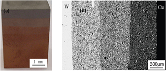
Figure 57. (a) W/Cu FGM mock-up by resistance sintering under ultrahigh pressure (RSUHP), and (b) its cross-sectional SEM micrograph [319]. Adapted with permission of Trans Tech Publications from [319].
Download figure:
Standard image High-resolution imageA Nd:YAG laser beam with a 10 ms pulse length, wavelength of 1064 nm and pulse frequency of 5 Hz was used for high heat load test on W/Cu FGM fabricated by RSUHP and infiltration welding. The laser beam diameter was about 2 mm. Argon was used to protect the samples from oxidation during the test.
After the high heat flux tests, micro cracking but no cratering occurred on the surface of the tungsten at the condition with laser energy density of 198 MW m−2, as shown in figure 58(a). It should be noted that obvious cratering occurred on pure tungsten samples fabricated by RSUHP at higher energy density. This demonstrates that W/Cu FGM has higher thermal resistance than pure tungsten. With higher energy density of 260 MW m−2 and duration of 10 s, crater morphology was found in the laser dot for all samples. The crater is enlarged when the hot impact time is increased, as shown in figure 58(b), revealing larger scale evaporation during the impact process [327, 328].
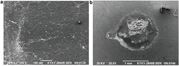
Figure 58. SEM micrograph of tungsten surface of a W/Cu FGM by resistance sintering under ultrahigh pressure (RSUHP) after high heat flux test: (a) energy density of 198 MW m−2, duration of 2 min, and (b) energy density of 220 MW m−2, duration of 1 min.
Download figure:
Standard image High-resolution image12.2.2. Infiltration-welding process.
Tungsten powders with average particle sizes of 3, 7, 15 μm and a purity of >99.5%, and Cu powder with a particle size less than 45 μm, and a purity of more than 99.9% were used as the starting materials. The processing includes three steps: (1) Fabrication a porous graded W skeleton; (2) Infiltration of the W skeleton with liquid Cu to form a W–Cu graded composite; (3) Joining W plate on the W rich surface of the W–Cu graded composite by using the rapidly solidified ribbon-type Ti based amorphous filler with a melting temperature of 850 °C [319]. The details of the steps have been recorded in [327].
It is found that the compositions have graded distribution in W–Cu graded composite, as shown in figure 59(a). Figure 59(b) shows the interface between pure tungsten and W–Cu graded composite joined by brazing. It can be seen that both interfaces between filler-metal with pure tungsten and W–Cu graded composite are homogeneous and pore-free. This demonstrates a very good wettability of the molten brazing alloy on the tungsten. The thermal conductivity of this W/Cu FGM was 155 W m−1 K−1 at room temperature. After thermal shock tests introduced in section 12.2.1, no obvious damage occurred, but heavy oxidation occurred in the graded layer after 30 cycles of quenching. No change occurred to the surface of the tungsten with W/Cu FGM after infiltration welding for 2 min hot impact in air with laser energy density of 198 MW m−2 introduced in section 12.2.1.
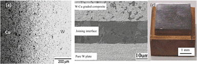
Figure 59. The morphology of (a) W–Cu graded composite; (b) interface morphology between W–Cu graded composite and pure tungsten; and (c) W/Cu FGM mock-up by infiltration-welding method.
Download figure:
Standard image High-resolution imageIn terms of FGM heat sink applications for a water-cooled divertor target, W/CuCrZr composite metals produced by liquid melt infiltration have been characterized extensively [329]. Figure 60(a) illustrates the thermal conductivity of the W/CuCrZr composite metals with three different compositions, namely 30 vol.%, 50 vol.%, and 70 vol.% W. It is seen that the composite with a W content of 30 vol.% exhibits a quite high thermal conductivity of about 300 W m−1 K−1 over a wide temperature range up to 600 °C. With an increasing W content, the thermal conductivity decreases accordingly but still yields notably higher conductivity values compared to pure W (thermal conductivity of pure W: 173 W m−1 K−1 at 20 °C, 147 W m−1 K−1 at 300 °C [11]).
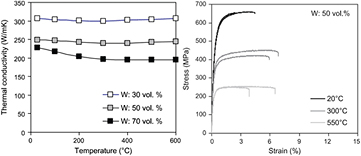
Figure 60. (a) Temperature dependence of thermal conductivity for three different compositions of W/CuCrZr composite metals; (b) Typical tensile stress-strain curves of a W/CuCrZr composite metal with 50 vol.% W at three different test temperatures.
Download figure:
Standard image High-resolution imageFigure 60(b) shows typical tensile stress-strain curves of a W/CuCrZr composite metal with 50 vol.% W at three test temperatures [329]. The curves indicate a considerable strengthening effect compared to the corresponding tensile strength values of CuCrZr alloy used as matrix material. The ultimate tensile stress values are notably higher compared to the monolithic CuCrZr alloy (minimum ultimate tensile stress of CuCrZr:  MPa at 20 °C,
  MPa at 300 °C [11]). However, it can be seen at the same time that the increase in strength does not come cost-free, as the ductility is notably reduced compared to monolithic CuCrZr (average total elongation of CuCrZr:
  % at 20 °C,
  at 300 °C [11]). Nevertheless, the latter feature does not seem to be a critical issue, as these ultimate tensile strain values are still substantially higher than the maximum strain that is expected to occur in the heat sink of a highly loaded PFC. For instance, in the case of an ITER-like divertor target under DEMO-relevant loading conditions, the peak plastic strain is predicted to be less than 1% according to finite element analysis (FEA) [95].
In order to verify the expected thermal and mechanical performance, as well as the structural reliability of the W/CuCrZr composite metals as FGM heat sink material, HHF fatigue tests were performed [330]. To this end, water-cooled demonstrator mock-ups with a rather simplified design were manufactured, as illustrated in figure 61(a) [330].
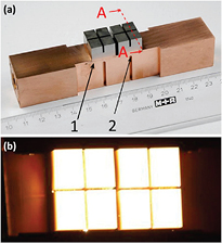
Figure 61. Water-cooled test mock-up consisting of castellated tungsten tiles, a CuCrZr heat sink block, and a functionally graded W/CuCrZr composite interlayer between the W armor and the CuCrZr heat sink (a) before and (b) during HHF testing. Adapted from [330], Copyright 2015, with permission from Elsevier.
Download figure:
Standard image High-resolution imageThey consisted of castellated flat tungsten tiles, a CuCrZr heat sink block, and a functionally graded W/CuCrZr interlayer bonded between the W armor and the CuCrZr heat sink. The W/CuCrZr composite interlayer consisted of three layers, differing in composition, with a thickness of approximately 1.5 mm for each layer. Details about the manufacturing process of the composite FGM, as well as of the mock-ups, can be found in [329, 330]. During the HHF fatigue tests, cyclic heat flux loads were applied to each of the three mock-ups at the hydrogen beam irradiation facility GLADIS at IPP Garching [138]. All three mock-ups withstood HHF loads of 15 MW m−2, while one of the mock-ups could be tested even up to 20 MW m−2, verifying the thermal and structural performance of the FGM heat sink as well as the joint mock-up successfully. Figure 62 shows a micrograph of the FGM interlayer after the HHF test illustrating fully intact microstructure without any visible cracks or defects. This result delivers the proof of principle demonstrating the high technological potential of melt infiltrated W/Cu composite metals as FGM heat sink materials for the design of a highly loaded PFC [330].
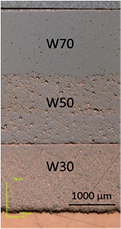
Figure 62. Micrograph of a W/CuCrZr composite interlayer after HHF loading up to 20 MW m−2 (3 cycles).
Download figure:
Standard image High-resolution image12.2.3. Plasma spraying.
Several initial sizes of W powder were investigated for plasma spraying, and the results show that the smaller the size of initial powder, the lower porosity of the coatings will be. The interlayer coating materials of W/Cu were obtained by mixing W and Cu powder with volume ratio of 50:50 and linearly graded [317, 331]. W/Cu mixtures and W powders were sprayed layer by layer on an oxygen-free copper substrate by atmosphere plasma spraying (APS) using a PT-A-3000 S plasma-spray facility made in Sweden. Argon was used as the plasma gas. Argon and nitrogen were used for cooling the substrates and preventing the coatings from oxidation. The detailed spraying parameters are given in [331]. The thickness of the W/Cu graded layer was 300 μm, and the maximum thickness of pure W coating was 3 mm.
As shown in figure 63, the W/Cu interlayer coating exhibits the typical lamellar structure, formed by overlapping W and Cu splats, with the tendency to form a layered structure. The porosity of the graded interlayer was about 5%, and the porosity of the pure W layer was about 12%. The bonding strength between the substrate and the coating was 23 MPa. The thermal conductivity of this W/Cu FGM was 57 W m−1 K−1 at room temperature. A Nd:YAG laser beam was used for high heat loading test on these specimens. Under the laser energy density of 152 MW m−2, almost no change occurred on all the coatings. But when the laser energy density was increased to 198 MW m−2, cracking, melting, and cratering appeared in all coatings after 240 cycles. Under the same conditions after 1200 cycles, peeling occurred on the surface of one sample and no peeling occurred on the coating surface of the other samples [331].

Figure 63. (A) Cross-sectional morphology of W/Cu FGM; (B) Surface morphology of W coating; (C) Cross-sectional morphology of W coating.
Download figure:
Standard image High-resolution imageAn electron beam with a 2 ms pulse width was used for high heat load tests. The energy density was 10 MW m−2. After 1000 cycles of hot impact, microcracks occurred in the W coating of the W/Cu FGM by APS and delamination occurred between the coating and the substrate. No obvious cracks occurred in the W/Cu FGM fabricated by the other two methods (RSUHP and infiltration-welding).
12.3. W/EUROFER97 FGM
Many experiments have already led successfully to tungsten/steel joints [332–338], either by brazing or diffusion bonding. Therein, a single thick Ti, V, Ni or Nb interlayer was used. In some cases additional thin Ti or Ni layers were inserted to increase the bonding strength. Remarkable shear and bending strengths were achieved at room and elevated temperatures. Nevertheless, high macroscopic internal stresses still prevent the maximum possible joint performance. In addition, to enable neutron irradiated material to be recycling friendly, high activation elements such as Nb, Mo, Ni, Cu, Al, Si and Co should be avoided.
Three fabrication methods capable of producing functionally graded tungsten/EUROFER97 layers are further illustrated in this section. These are resistance sintering under ultrahigh pressure (RSUHP), magnetron sputtering, and vacuum plasma spraying (VPS).
12.3.1. Resistance sintering under ultra-high pressure.
The large difference of the melting point (about 1900 °C) between tungsten and steel impedes conventional sintering, due to the lack of an overlap in sintering temperatures. Nevertheless, the successful sintering of both metals has been demonstrated by RSUHP and optimized in [339].
W powder with an average particle size of 2 μm and EUROFER97 powder (spheroidized in nitrogen) with a particle size of d50 = 50 μm served as raw materials. Both powders are mixed in an agate mortar with different volume ratios according to the composition design. In this work, samples with four layers at different compositions, ranging from 20 to 80 vol.% EUROFER97 in 20 vol.% steps, were fabricated, see figure 64(a). The avoidance of too high temperatures or even the melting of EUROFER97 particles is of major importance for the selection of process parameters. Thus the temperature was chosen to be less than 1200 °C, which is much lower than the normal sintering temperature of W powders in the absence of any sintering aid. Nevertheless, the temperature at the interface of W particles should be very high, due to the high contact resistance on the particle interface; thus surface diffusion or even surface melting may occur quickly, and particles are fused together in the presence of strong current. The thickness of the outer two layers was 3 mm, and for the inner two layers it was 0.5 mm. The microscopic analysis revealed a microstructure of good quality, free of cracks and very low porosity (<2%).
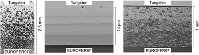
Figure 64. (a) RSUHP-FGM (resistance sintering under ultrahigh pressure), (b) magnetron sputtered FGM diffusion bonded to W and EUROFER97, (c) VPS (vacuum plasma sprayed) FGM diffusion bonded to EUROFER97 and tungsten with a thin vanadium interlayer.
Download figure:
Standard image High-resolution imageA drawback is the current role of matrix (tungsten) and particulate (EUROFER97), since the composite behaves almost as tungsten. The opposite case, a composite whose ductile steel matrix hosts hard tungsten particles could improve the ductility of this composite.
12.3.2. Magnetron sputtering.
In this experiment [312] a graded layer could be realized by a four step multilayer design (figure 64(b)). It should be noted that the realization of a continuous step-less gradation is also feasible. The microstructure is amorphous or nanocrystalline (depending on the mixing ratio). This very important aspect offers the chance to profit from the superior materials properties due to the ultra-fine grained/nanocrystalline microstructure. All sputtered coatings exhibit a dense microstructure with no remarkable porosity after a slight polishing with oxide polishing suspension. However, a major drawback of magnetron sputtering is the thickness of sputtered tungsten coatings, which is limited to ∼30 μm [340].
12.3.3. Vacuum plasma spraying (VPS).
In early experiments, graded W/steel composites on W substrates have already been successfully produced by VPS [341]. Unfortunately, a major drawback was the high porosity. A high material density very close to the theoretical density and a high thermal conductivity are essential when used as coating for a plasma facing component. An improved density was achieved in [312], being well below 4 vol.%. The multilayer structure of VPS composites, typical for coatings in an early development stage, could also be achieved by an appropriate focussing of both particle trajectories. Nevertheless, the adhesion of these VPS coatings on the substrate was insufficient. The reason for the poor interfacial strength might be that the tungsten substrate roughness was not high enough, as bonding is only formed by mechanical clamping. A systematic roughening or sculpturing of the substrate surface can improve the adhesion [309]. To overcome the lack of interfacial strength, a thin vanadium foil with a thickness of 20 μm was used in [312] for the bonding to WL10. This does not result in an additional production step, as the vanadium interlayer can be joined to the tungsten using the same diffusion bonding parameters as for the EUROFER97 side. Such an interlayer is necessary, since diffusion at 800 °C between two tungsten surfaces is not sufficient.
Functionally graded coatings were produced [312] with a thickness of up to 1 mm (figure 64(c)), but thicker tungsten-based coatings up to several millimeters are also possible. Based on the images taken by optical and scanning electron microscopy, a microstructure of good quality with no cracks and a porosity <4% can be observed. However, cavities with a size up to 20 μm are strewn along the sample volume.
Heat treatments at different temperatures for one hour revealed insights on the thermal stability of the sprayed tungsten/EUROFER97 composites. For all the tested temperatures up to 1100 °C, no cracks were visible by the SEM, either in the EUROFER97 or in the tungsten regions [312]. However, gaps between both materials arose when the temperature was equal to or higher than 1000 °C for one hour.
VPS is suitable for the production of functionally graded EUROFER97/tungsten coatings, which can act as interlayers for joining EUROFER97 and tungsten bulk material by diffusion bonding at 800 °C. No phase formation or change in chemical composition in the functionally graded layers could be detected after the bonding process. The produced joints were thermally cycled ten times between 20 °C and 650 °C, and proved their basic capability to withstand the operating conditions in a future fusion reactor. This is an improvement in comparison to the direct diffusion bonding of EUROFER97 and tungsten at 1050 °C, where all samples fell apart in the post bonding heat treatment [342]. Certainly, the low welding temperature of 800 °C, which avoids the austenite phase formation of EUROFER97 at T > 800 °C, and reduces thermally induced stresses during the cooling down, is a very positive circumstance. In addition, the gradation helps to reduce thermally induced macroscopic stresses as it has been assessed numerically in [46].
The application of functionally graded tungsten/steel material is not limited to divertor components, since it is also considered as erosion protective coating for the plasma-facing first wall.
Based on the simulation results summarized in section 12.1.2, FG tungsten/EUROFER97 coating systems on EUROFER97 substrates are fabricated by VPS for FW application. Three and five layers with linear variation of the compositional ratio are introduced as representatives of stepwise linear gradation of FG-layer. The as-received surface morphology and cross-sectional structures of both types are shown in figure 65. The surfaces have a smooth structure, which indicates that particles melted well during the spraying process and re-solidified, forming a pancake-like structure. In addition, several spherical particles of about 10 μm exist on the surface, which are un-melted tungsten particles. The cross-sectional SEM micrographs show that stepwise linear gradation is formed successfully between the tungsten coating and the EUROFER97 substrate, and that there is no obvious interface between layers of the FG-layer, especially for coating with five layers, which has a finer gradation. Nominal and true concentrations of tungsten in percent by volume are investigated by using EDS, as shown in figure 66(a). True concentrations of tungsten are quite consistent for the case of 25% and 63% nominal value, while the true values are a little lower than the nominal value for other cases. However, the true concentrations as desired follow a (globally) linear gradation over the number of layers as it can be seen in figure 66(a). The thicknesses of the coatings with three layers are shown in figure 66(b). No delamination is observed for both coatings [343].
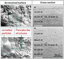
Figure 65. As-received surface morphology and cross-sectional structures of tungsten coating with three and five functionally graded layers, respectively.
Download figure:
Standard image High-resolution image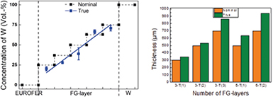
Figure 66. (a) Gradation of functionally graded (FG) layers; (b) Nominal and true thickness variation of FG-layer. (The sample labeling n-T(i) is given by the number of layers n and the total thickness index i).
Download figure:
Standard image High-resolution imageAs shown in figure 67, coatings are characterized by re-solidified pancake-like deposition with columnar structure of tungsten. The size of the columnar crystals is 2–4 μm in height, and the columnar crystal is radially oriented perpendicular to the substrate. In addition, un-melted particles and irregular pores of several micrometers in size exist in the tungsten coating, as well as in the FG-layer. Most pores occur around un-melted particles and at interfaces among lamellar layers. It is noted that no cracks or delamination could be observed in tungsten coating and FG-layer. It is assumed that the porous structure constrains the propagation of fissures or cracks [341].

Figure 67. SEM micrographs showing characteristics of tungsten coating, functionally graded layer and interfaces.
Download figure:
Standard image High-resolution image
The optimization of spraying parameters and vacuum accompanied by proper melting and re-solidification of powders yields the lowest porosity of all coatings. In particular, the porosity of the tungsten coating is ∼4% according to the image analysis, and that of the FG-layer is less than 2%. It seems that the low melting point and ductility of EUROFER97 powders provide flowing of melted metal, which yields low porosity. Despite some gap-like defects, sound interfaces between the FG-layer and the EUROFER97 substrate are observed (see figure 67) [343].
12.4. Conclusion
For the assessment and design of W/Cu and W/EUROFER97 FGM finite element simulations are performed. Reduction of residual stresses and inelastic strains as well as remarkable improvement of life time are observed by introducing of FGM. The two kinds of FGMs (W/Cu FGM and W/EUROFER97 FGM) are realized and developed by several fabrication methods.
Both are fabricated by RSUHP (resistance sintering under ultra-high pressure). Thereby the remarkable advantages of this method are demonstrated, in particular that the whole composition spectrum can be achieved and the designed composition distributions can be maintained due to short duration of graded sintering. In addition, the thickness of the W layers can be larger than 1 mm, and a pure W layer can achieve high density even without sintering additive. However, only small samples can be fabricated to date, which may restrict its use from an engineering viewpoint.
For the process of Cu infiltration into graded W by porous skeleton welding, the following advantages are evident: the whole composition spectrum can be realized—continuously graded composite distribution without visible interface can be achieved; thickness of the W layer can be larger than 1 mm, and the performance of the W layer can be adjusted through welding different grade of W plate. The performance under high heat load is excellent. W/Cu FGM produced by this method is a promising candidate for PFCs in the next step fusion reactor.
For W/EUROFER97 FGM fabricated by magnetron sputtering, the realization of a continuous step-less gradation is feasible. The sputtered coatings exhibit a dense microstructure with no remarkable porosity. However, a major drawback of magnetron sputtering is the limited thickness of sputtered tungsten coating.
For W/Cu FGM fabricated by APS, the obvious beneficial features are favourable, such as in situ operation for repairing and complex shapes, large scale components, cost-effective, wide composition spectrum; but the high porosity and the low bonding strength are the main drawbacks of APS. Compared to APS, W/EUROFER97 FGM fabricated by VPS shows the same obvious beneficial features, and in addition low porosity and interface, with high bonding strength toughness.
The fabrication of W/Cu FGM is well developed, and the performance of water-cooled demonstrator W/Cu FGM mock-ups under high heat load is also well investigated. The W/EUROFER97 FGM and the further FG W/EUROFER97 mock-ups, particularly VPS W/EUROFER97 FGM, are in progress and promising, particularly for FW application in DEMO.
13. Concluding remarks
Several of the materials concepts described in this manuscript are in early development stages, e.g. proof-of-principle or proof-of-concept. Some have entered the technology development stage, and a further development towards technology demonstration is still required before a DEMO engineering design can fully benefit from these materials and components. Nevertheless, compared to baseline materials, the advanced concepts described here already demonstrate that they open promising routes towards the design of a DEMO or fusion power reactor. Their potential lies in the capability to deal with operational degradation of materials, by e.g. high temperatures, cyclic loads, and neutron irradiation with significant fluences. They will allow the design of a fusion power device along the construction principles demonstrated in current machines like JET, ASDEX Upgrade, DIII-D, JT-60SA, EAST etc—and of course ITER. In particular, their mature divertor and first wall concepts can be transferred to a DEMO device, allowing utilisation of the huge experience accumulated over decades of successful operation of these devices.
Still to be demonstrated for the advanced materials concepts described here is their benign behavior under neutron impact. Until now, the first irradiation experiments with advanced materials are currently in the planning stage, e.g. under the umbrella of the European EUROfusion materials program, and no concluding results from post-irradiation examinations of some very first irradiation campaigns are presently available. In the next few years these neutron irradiation tests are of high priority.
In parallel, it has to be demonstrated that the advanced materials can be combined into components, employing the newly developed bonding concepts and graded materials. These advanced components will then have to undergo high heat flux tests and linear plasma exposure tests—in dedicated high heat flux and plasma devices as well as in confinement devices—as are being performed already for the baseline materials. In addition, high heat flux tests after neutron irradiation will have to demonstrate that the superior behavior of the advanced materials and bonding technologies are still present after combining them into components. These tests will require extended testing capabilities, in particular for irradiated components, in devices located in hot cell facilities 16 .
Given the promising properties of the advanced materials and bonding technologies currently under development, as described in this manuscript, the realization of fusion energy by tokamaks and stellarators designed along the lines of currently operated confinement devices seems feasible. The additional demands resulting from power production (safety, reliability, neutron compatibility, tritium efficiency etc) compared to experimental fusion devices are addressed and satisfied by these materials solutions. The advanced materials and components will allow the design, construction and operation of such a fusion power device employing the design concepts realized in ITER. They are a crucial contribution towards the realization of fusion energy as a future electricity source.
Acknowledgments
Part of the work described here has been carried out within the framework of the EUROfusion Consortium and has received funding from the Euratom research and training program 2014-2018 under grant agreement No 633053. The views and opinions expressed herein do not necessarily reflect those of the European Commission.
The authors are grateful for the support of the EO-Service GmbH, TESCAN.
The authors thank their colleagues from PLANSEE SE, the Technical University of Madrid (UPM), and the Karlsruhe Institute of Technology (KIT), for their support and valuable contributions.
The contributions of Dr. H. Traxler (PLANSEE SE), S. Baumgärtner (KIT, three-point bending tests), D. Bolich (KIT, measurement of the hardness), M. Hoffmann (KIT, scanning electron microscopy), B. Dafferner (KIT, Charpy impact tests), M. Kärcher (KIT, Charpy impact tests), and J. Konrad (KIT, mockup fabrication) are gratefully acknowledged.
The authors express their sincere gratitude to researchers and students who have contributed to ductilization of refractory transition metals. Support by grant-in-aid is also appreciated.
Footnotes
- 11
See also: Ueda et al Status of the Development of Baseline High Heat Flux and Plasma Facing Materials for Fusion, this special issue
- 12
See also: Linsmeier et al Material testing facilities and programs for plasma-facing component testing, this special issue
- 13
Ueda et al Status of the Development of Baseline High Heat Flux and Plasma Facing Materials for Fusion, this special issue
- 14
Federici et al European DEMO design strategy and consequences for materials, this special issue
- 15
As the matrix itself is intrinsically brittle and is not modified by the fibres, linear elastic fracture mechanics is applicable.
- 16
See also: Linsmeier et al Material testing facilities and programs for plasma-facing component testing, this special issue