
Abstract
Patients suffering from neuronal degenerative diseases are increasingly being equipped with neural implants to treat symptoms or restore functions and increase their quality of life. Magnetic resonance imaging (MRI) would be the modality of choice for the diagnosis and compulsory postoperative monitoring of such patients. However, interactions between the magnetic resonance (MR) environment and implants pose severe health risks to the patient. Nevertheless, neural implant recipients regularly undergo MRI examinations, and adverse events are rarely reported. However, this should not imply that the procedures are safe. More than 300 000 cochlear implant recipients are excluded from MRI, unless the indication outweighs the excruciating pain. For 75 000 deep brain stimulation (DBS) recipients quite the opposite holds true: MRI is considered an essential part of the implantation procedure and some medical centres deliberately exceed safety regulations, which they refer to as crucially impractical. Permanent MRI-related neurological dysfunctions in DBS recipients have occurred in the past when manufacturer recommendations were exceeded. Within the last few decades, extensive effort has been invested to identify, characterise and quantify the occurring interactions. Yet today we are still far from a satisfying solution concerning a safe and beneficial MR procedure for all implant recipients. To contribute, we intend to raise awareness of the growing concern, summon the community to stop absurdities and instead improve the situation for the increasing number of patients. Therefore, we review implant safety in the MRI literature from an engineering point of view, with a focus on cochlear and DBS implants as success stories of neural implants in clinical practice. We briefly explain fundamental phenomena which can lead to patient harm, and point out breakthroughs and errors made. Then, we end with conclusions and strategies to avoid future implants from being contraindicated in MR examinations. We believe that implant recipients should enter MRI, but before doing so, it should be made sure that the procedure is reasonable.
Export citation and abstract BibTeX RIS

Original content from this work may be used under the terms of the Creative Commons Attribution 3.0 licence. Any further distribution of this work must maintain attribution to the author(s) and the title of the work, journal citation and DOI.
1. Introduction
Bioelectronic devices in the human body, especially neural implants, have proven themselves as success stories hundreds of thousands of times [1, 2]. They are used to restore body functions, improve the quality of life of patients with neuronal degenerative diseases, and still have great potential for ground-breaking novel applications. For the bright future of neural implants to be fulfilled, magnetic resonance imaging (MRI), with its striking soft tissue contrast, is the only technology that is sufficient for appropriate diagnosis and that guarantees the compulsory monitoring of implant recipients' most delicate organ: the brain. The active implants and bioelectric medicine in MRI result in a complex system. Hermetic packages, batteries, cables and electrodes that interface technology with tissue require many different materials. These materials face a harsh magnetic resonance (MR) environment, including an extremely powerful static magnetic field, potent radio frequency excitation, and rapidly switching gradient fields. An encounter between implants and the MR environment can result in the following interactions: exertion of force, voltage induction, heating and imaging artefacts (figure 1). As this has led to fatal incidents in the past, many neural implants are considered to be an absolute contraindication to MRI as a precaution. Along with MRI becoming the gold standard for many common medical conditions [3, 4], the number of implant recipients requiring diagnostic MRI is continuously increasing [5–8]. Additionally, aspects in favour of MRI include its non-ionising property and its versatile application range beyond static images such as in angiography [9] or functional MRI (fMRI). Extensive effort has been made to identify, characterise and quantify the occurring interactions over the last three and a half decades [10–18]. Yet, today we are still far from a satisfying understanding of the occurring phenomena.

Figure 1. The complex MR environment can interact with an implant in many different ways which may cause hazardous conditions. Forces may occur from gradient coil fields and static fields interacting with the implant. Voltages may be induced by the time variant gradient and RF fields or by rapid transportation of the patient towards the scanner. Heating effects originate from the electric fields of the time variant magnetic fields, where the main contribution is by the powerful radio frequency pulses. Artefacts are mainly attributed to the B0-field by virtue of its deviation caused by susceptibility mismatch, and on the RF field depending on the used sequence. The correlation between the hazard and the MR component is displayed by grey-scaled dots in a table format, where the intensity gives an indication of how severe this interaction can become.
Download figure:
Standard image High-resolution imageAs we develop future generation neural implants, we choose as educational guides cochlear implants (CI) and deep brain stimulation (DBS) implants, with the intention of drawing lessons from the experience of these abundant commercial neural devices in the MRI environment. We chose DBS as a representative for implants featuring spatially spread-out components with long conductors, an implanted energy source, and with the implant–tissue interface located in a delicate target area of the central nervous system. The CI was chosen for its spatially compact component arrangement featuring short cables, a permanent magnet, and an external energy source. We believe that with these two very different implant variants, the most important aspects of implant components and their behaviour in MRI are covered (table 1). Additionally, being inserted into the head, they compare better than the more abundant cardiac pacemakers (CP) and spinal cord stimulators (SCS). Furthermore, non-invasive MRI is indispensable for brain imaging and monitoring, and few satisfying alternatives are available. The assessment of the exact risk for the individual patient remains open. In practice, CI recipients often experience excruciating pain when undertaking MRI [3, 6, 19–27]. It is noteworthy that CIs are labelled with demonstrated safety in the MR environment within defined conditions [28, 29]. Another questionable example is when DBS recipients undergo MRI, as this exposes them to the risk of brain tissue burns [30–32]. Nevertheless, patients with implants are regularly examined in MRI [32–39]. However, despite rarely reported adverse events, we insist that it is of paramount importance to understand that the absence of adverse events is not equivalent to demonstrating safety [40].
Table 1. Comparison of the magnitude of interactions of CI, DBS, SCS, CP with the MR environment.
| Interaction | DBS | CI | SCS [41–43] | CP [44–46] |
|---|---|---|---|---|
| Force | + | +++ + | ++ | ++ |
| Induced voltage | ++ | ++ | +++ | +++ + |
| Heating | +++ + | + | +++ | ++ |
| Artefacts | +++ | +++ + | + | + |
+ ++ + Very strong +++Serious + + Moderate + Negligible
As Thornton provides an excellent summary from a medical perspective [47], it is obvious that we cannot stop imaging implants in MRI, and that we should not do so either. However, we should ask ourselves: where does the risk come from? And what are the underlying physical effects? What experiences are reported? How can the biomedical community merge bioelectronic devices and MRI to improve the situation for the current patient with a life-long implant? What lessons can be learned from already established implants to prevent restrictions to MRI owing to successful treatment? How can future implants gain safe access to MRI despite the trend towards more powerful electromagnetic fields? To address these questions, we collected information considering medical, physical and engineering points of view, to assemble a larger picture of interactions between the MR environment and implants. This creates a vantage point among the disciplines from which to ultimately answer the questions for a broad audience. We provide the groundwork by discussing the interaction pathways of an MRI scan between the patient, implant, MR unit and physician, and how they can lead to health-threatening situations. This is complemented by a review of MR safety literature, with a focus on CI and DBS as examples, with most clinical experience supplemented by other bioelectronic devices. In addition, we aspire to question current paradigms such as the head wrap for CIs in MRI, and suggest improvements. Finally, we aim to benefit from the lessons learned for the development of future implantable technologies. We point out safety aspects for future implants, in particular bioelectronic microdevices, from an engineering point of view, to reduce the risks for implant recipients, so that they can benefit from both the treatment with the implant and the diagnostic value of MRI.
2. Fundamentals, interaction pathways and resulting hazards
MRI is considered a safe procedure, and the lack of emitted ionising radiation allows for unlimited use. Currently, the majority of clinical MR scanners operate at 1.5 T, with 3 T MR units being the second most prevalent, while the legal limit for clinical imaging has recently even been elevated to 8 T [48]. Along with the development of more powerful MRI equipment and an increasing number of MR examinations, the number of adverse events in combination with implants has grown [6, 23, 27, 30–32, 49–51]. In this section we briefly introduce the fundamentals of MRI and neural implant components, and visualise the interaction pathways among them in figure 2 to give a more detailed understanding of this alarming direction.

Figure 2. A detailed map of interaction pathways between the patient, brain implant, the MR environment and the responsible physician. The interaction pathways which only occur with implants are in addition to the ones displayed above and those that occur without an implant. It is worth noting the tremendous increase of hazardous pathways resulting from the introduction of an implant. The strength of individual interactions depends on the implant, the MR unit, and the applied acquisition sequence.
Download figure:
Standard image High-resolution image2.1. Basic MRI background
2.1.1. Hardware and electromagnetic fields.
An MR unit is a machine that maintains three qualitatively different electromagnetic fields, and their precise control allows an MR image to be acquired. The basic functional principle is as follows: (1) A strong, homogeneous static magnetic field, called the B0-field, is created within the bore of the MR scanner. Its purpose is the polarisation of half-integer nuclear spins along the z-axis. The net magnetisation exposed to an external magnetic field will precess at the Larmor frequency ω which is related to B0 and the gyromagnetic ratio γ = 42.25 MHz T−1 such that  . (2) Powerful radio frequency (RF) pulses are driven at the Larmor frequency, thereby flipping the magnetisation out of its alignment direction. In turn, the flipped and precessing magnetisation now induces a signal in the receiver coils. The relaxation characteristics of the excited nuclei differ among tissue types and thus enable tissue contrast after signal acquisition. (3) Another 'layer' of weak magnetic fields arranged as a spatial gradient in three orthogonal directions is selectively superimposed onto the B0-field. This alters the precession frequency of the nuclei as a function of position and hence allows the spatial separation of the measured signals into volume elements (voxels) through spatial encoding of the obtained signal. The gradient magnetic field is rapidly switched on and off during MR acquisition at a frequency of some kHz. After recording, the data is computationally assembled into an MR image.
2.1.2. Image acquisition sequences.
The greatest strength of MRI lies in its potential to measure a large number of various physical parameters, such as relaxation times, proton density, flow and diffusion, temperature, abundance of molecules and oxygenation of blood, all with the same hardware. This flexibility is achieved by the software-controlled adjustment of timing and magnitude parameters for the RF and gradient fields. The imaging recipe, which is a chronological ordering of RF and gradient field switching, is called an imaging sequence, and is usually displayed in a timing diagram. All sequences are based on fundamental blocks such as the gradient-echo (GE) or spin-echo (SE) sequence; hence, fMRI or other advanced recording techniques utilise modified standard imaging blocks.
What is the effect of different sequences on the hazards that implant recipients are facing inside the MRI? Indeed, because the hardware does not change, the type of hazard is equal for all possible imaging sequences, i.e. it is the magnitude of the interactions which depends strongly on the sequence used, because the timing and the resulting magnitude of the generated magnetic fields varies with the applied sequences. Hazard levels with respect to RF interactions depend on the power and number of RF pulses per unit time, defining the RF power deposition (SAR level). SE sequences, for example, make use of many RF refocusing pulses. This leads to a larger number of RF pulses per unit time compared to the GE sequences [52], and as a consequence, to a higher RF power deposition. Similarly, the gradient slew rate and the number of gradient switching operations per unit time determine the strength of gradient-dependent interactions. fMRI is particularly vulnerable to influence from implants. The most widespread application is the detection of the blood-oxygen-level-dependent (BOLD) signal in the brain as an indicator for nerve cell activity [53]. It is the small difference in the magnetic susceptibility of venous blood to its vicinity that enables the BOLD contrast. Consequently, interference with the magnetic susceptibility of implants can be detrimental as the acquired echo-planar imaging (EPI) data is very sensitive to image distortion from susceptibility gradients due to the low bandwidth in the phase encoding direction [53].
2.2. Neural implants
Neural implants interface the nervous system to either record electrical nerve activity or to electrically stimulate nerve cells and fibres (figure 3). Legally, they are classified as active implantable medical devices (AIMD), which means that they contain an energy source. The energy source can be a battery, a wireless link via a coil, which is called inductive coupling, or any other energy source other than gravity. It powers all the electronics that are needed to amplify, process and transmit nerve signals or generate current pulses for the stimulation of neural tissue. The power source and electronics need protection from the harsh environment of water, ions, proteins and cells in the body. On the other hand, the body environment also needs protection from the potentially toxic agents of the circuity. The most common solution is a hermetic (water and gas tight) housing made of titanium or ceramic material. Such hermetic packages are essential for long-term implants.
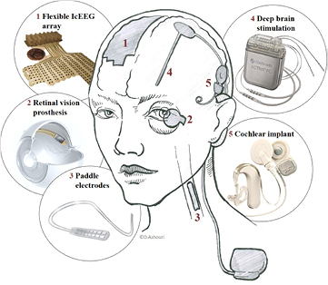
Figure 3. Various neural implants and the location where they interface the central nervous system. This schematic display shows the wide-spread DBS device and the compact CI system with their individual components on the right side and the location where they are implanted. The left side shows implants with a lower occurrence. ((2) Adapted from [54], (3) image courtesy of Medtronic, (4) adapted from [55], (5) adapted from [56]).
Download figure:
Standard image High-resolution imageThe dimensions of implant components vary between a few tens of micrometres for electrode sites in retina implants, slightly more than a millimetre in diameter for the CI and DBS electrodes, a couple of centimetres for the hermetic package, and up to a metre of cable length for DBS leads. The choice of materials commonly used for implant fabrication is restricted by requirements of biocompatibility and longevity. When considering implants for the MR environment, more restrictions concerning the material choice apply. One important material property is the magnetic susceptibility χ, which indicates the degree of magnetisation of a material in response to an applied external magnetic field. The value of the magnetic susceptibility can indicate the magnitude of force and imaging artefact size that are to be expected in MRI from a specific material. A list of common implant materials and their magnetic susceptibilities is shown in table 2.
Table 2. Table of materials and their magnetic susceptibility. Negative values represent materials that counteract the external magnetic field, while positive values strengthen the overall magnetic field. The greater the mismatch in magnetic susceptibility of two adjacent materials, the larger the resulting imaging artefacts. Ferromagnetic materials experience attractive forces and will thus move, or even turn into projectiles.
| Material | Magnetic susceptibility  in ppm in ppm |
Scope of application / note | Reference |
|---|---|---|---|
| Gold | −34 | Electrodes | [94] |
| Solder (Sn60Pb38Cu2) | Sn: −22.7 | Connection of electric components | [94] |
| Pb: −15.8 | |||
| Cu: −9.63 | |||
| Alumina | −18.16 | Hermetic packaging | [94] |
| Copper | −9.63 | Toxic | [94] |
| Polyimid | −8.917 | Non-hermetic packaging, substrate | [95] |
| Human tissue | −11 to −7 | [94] | |
| Water | −9.0302 | [96] | |
| Silicone (Sylgard 184) | −8.105 | Non-hermetic packaging | [95] |
| Silicon (Si) | −4.2 | Semi-conducting substrate for electronics | [94] |
| Titanium | 182 | Hermetic packaging | [94] |
| Platinum | 279 | Electrodes, noble, inert, biocompatible | [94] |
| Austenitic stainless steel 316 | 9000 | ferromagnetic, electrodes | [97] |
| Iron | 200 · 109 | ferromagnetic | [94] |
2.3. Physical background of hazardous implant–MRI interactions
While MRI is generally considered safe, the introduction of patients with implants into the MR system generates hazards. A hazard is defined as a potential source of harm [57], which may lead to health impairment or loss of the quality of life. An adverse event is defined by the United States Food and Drug Administration (FDA) as 'any undesirable experience associated with the use of a medical product in a patient'. In general, every surgical intervention in the brain poses a high risk to the patient. This means that the implantation of a device is already hazardous. Consequently, any additional surgery caused by an adverse event or malfunction of the device, both of which could be caused by an MRI examination, has to be prevented. The brain represents some of the most delicate tissue in the human body. As such, it is especially sensitive to thermal [58–60], mechanical [61] and electromagnetic impact [62]. In the following we introduce the underlying mechanisms that act between implants and MRI, which may lead to consequences for the patient: heating, exertion of force, induced voltages, device reimplantation due to dysfunction, and imaging artefacts that impede diagnosis (figure 4).

Figure 4. Hazardous MRI-implant interactions and their consequences for the patient. (A)–(C) Modalities for the evaluation of heating: (A) MR thermometry in a porcine brain, (B) the according simulation, (C) an optical temperature sensor mounted to a DBS probe for heating evaluation in phantoms. (A) and (B) show a temperature rise of 5 °C around the DBS probe, which can cause severe permanent brain trauma. (D) Application of a head wrap to secure the internal magnet of the CI against dislocation. Radiographs after an MRI examination reveal the internal magnet in the intended position (E) and dislocated (F). Dislocation results in pain, tissue damage and implant dysfunction. (G) Induced voltages in the signal output of the implanted electrode coincide with gradient field switching. This may lead to unintended stimulation and device malfunction. (H) and (I) MRI artefacts obscure large parts of the brain due to B0 field distortions caused by the internal magnet of a CI. Artefacts can compromise diagnosis and may cause misinterpretations. ((A)–(C) Adapted from [63] (© 2012 Institute of Physics and Engineering in Medicine. All rights reserved), (D) adapted from [8] (© 2010 Otology & Neurotology, Inc), (E) and (F) adapted from [64] (Copyright © 2014, Rights Managed by Georg Thieme Verlag KG Stuttgart • New York), (G) adapted from [65] (John Wiley & Sons. © 2015 Wiley Periodicals, Inc.), (H) and (I) adapted from [26] (CC BY 4.0.)).
Download figure:
Standard image High-resolution image2.3.1. Induced voltages.
An electric voltage is induced in an electrically conducting material whenever the magnetic flux  passing through the area A of the material changes over time (figure 5(a)). The induced voltage is given by Faraday's law of induction,


Figure 5. The most important physical interactions in electromagnetic fields. (a) Induced voltages and currents due to a time-varying magnetic field. (b) Magnetisation of materials. (c) The magnetic moment of a current loop. (d) The linear force; the magnetised object is attracted towards increasing magnetic flux density (denser field lines). (e) Rotational force; the torque (green arrow) is orthogonal to the magnetic moment and the magnetic field, i.e. the rotational force (red arrow) is in the plane of the magnetic moment and magnetic field. (f) Absorption (heating) of the RF field on metal surfaces. (g) An illustration of the destructive interference of the resonance signal due to an inhomogeneous magnetic field in a voxel.
Download figure:
Standard image High-resolution imageThis results in an induced electric current—the 'eddy current'
if the electrical resistance of the loop is finite, i.e. for a closed conductive loop, or an open loop with an attached circuit with finite resistance. When the law of induction is applied to the situation of implant recipients in an MR environment, it becomes clear that implant geometry, the movement of the patient relative to the scanner, and the switching gradient field are relevant. Three typical situations during MRI examination may lead to induced voltages: (1) When the patient is moved towards and into the MR scanner. In this case the magnetic flux density increases from near zero outside the scanner room to the maximum value of B0. The magnitude of induced voltage depends on the speed at which the patient is moved. (2) Inside and in the direct surroundings of the MR scanner (i.e. in the spatially varying fringe field of the scanner), any movement of the patient that results in rotation of the implant with respect to the magnetic field may induce a relevant voltage. (3) During MR image acquisition, the rapid switching of the gradient fields induce an alternating voltage at the corresponding frequency, usually in the kHz range. To provide an example, the voltage induced in a  loop perpendicular to a magnetic field change of 1 T per second is 10 mV. If this loop is a short-circuited copper wire with a
  cross section, the eddy current will be
  . These numbers scale proportionally to the frequency and to the cross-sectional area, and are highly dependent on the geometry. The induction of voltages and eddy currents in a device may cause unintentional electrical stimulation of the (nervous) tissue. This has caused life-threatening situations for CP patients in the past [91–93]. Such situations are unlikely to happen with neural implants as they do not support vital functions. However, artefacts in the data recordings or damage to the implant may occur, which consequently can make device reimplantation necessary.
2.3.2. Exertion of force.
Magnetic forces result from the interaction of a magnetic moment with a magnetic field and may lead to movement relative to the surrounding tissue. The magnetic moment is essentially the strength of a permanent magnet. It is also caused by the magnetisation of any material when exposed to an external magnetic field such as the B0 field of an MR environment, with a magnitude proportional to the magnetic susceptibility  (see table 2) and its volume V:
  , see figure 5(b).
Materials are distinguished into three different categories according to their value of magnetic susceptibility. The force exerted by diamagnetic ( ) and paramagnetic materials (
 ) in MRI with
  is negligible. However, even small amounts of ferromagnetic material with
  may exert a significant force.
A magnetic moment is also exerted by currents around a closed loop, such as the eddy currents described by equation (2). It is perpendicular and proportional to the surface area A of the loop,  (see figure 5(c)), or, in the case of eddy currents, described by equation (2):
  . This may occur when the patient is moved in or out of the MR scanner, or moves during imaging. The interaction of a magnetic moment with a magnetic field gradient causes a linear force
  (figure 5(d)), while a tilt of the magnetic moment relative to the magnetic field causes a torque
  (rotational force, figure 5(e)):

The important points are, on the one hand, that linear force only arises in regions with a magnetic gradient, i.e. at the entrance of the scanner and during the imaging procedure. For example a  piece of 'non-magnetic' 316 stainless steel (see table 2) is magnetised by a
  magnetic field to exert a magnetic moment of
  . A
. A  gradient then creates a force of
  —14% of its weight of
  . A
. A  neodymium magnet with a magnetic moment of
  would, in the same situation, be subject to a force of
  —11 times its weight.
The rotational force, however, arises only when the magnetic moment of the material is not parallel to the magnetic field, and hence it does not occur in paramagnetic materials that are magnetised by the magnetic field, but only in permanent magnets, ferromagnetic materials with hysteresis, or in conductors with induced eddy currents. The  neodymium magnet, for example, perpendicular to a
  magnetic field is subject to a torque of
  . This corresponds to its weight acting on a
  long lever.
The  conductor loop in a time-varying magnetic field of
  described in section 2.3.1 exerts a magnetic moment of
  , similar to the
  neodymium magnet. The exertion of force onto an implanted device may result in mechanical stress on the tissue and thus severe pain. The dislocation of an implanted magnet can compromise the device function and make surgical intervention necessary.
2.3.3. Heating.
The specific absorption rate (SAR) measured in units of power per mass: (W kg−1) quantifies the absorption of electromagnetic fields in a material and results in heating. The interaction between the RF field and water molecules causes the heating of tissue and, even without an implant, poses a risk to the patient during MRI procedures [98, 99]. Conductive materials, however, interact differently with the RF field and may be subject to more intense heating [100]. An RF field that is incident to a metal surface will be partially reflected and partially transmitted into the material (figure 5(f)). The transmitted fraction is absorbed and converted into heat. While this is a microscopic process that is independent of the shape of the object, it may be greatly enhanced whenever a system is in resonance with the RF field due to its macroscopic structure. This occurs on a small scale when the resonant frequency  of a circuit with inductance L and capacitance C matches the RF frequency. On a larger scale, a similar effect occurs when the length of a conductor is a multiple [101], the same, or an integer fraction (half or quarter) [102] of the RF wavelength. Note that the cables for active implants are often helical wound wires to allow the elongation caused by body movement. Thus, the effective wire length may be a multiple of the cable length. The RF wavelength scales inversely proportional to the B0 field strength and is further reduced by the relative permittivity
  of the surrounding medium (tissue),
  . With
  for the tissue and the RF at a frequency of 100 MHz [103], the RF wavelength is
  for a 1.5 T scanner or
  at 3 T, so the half or quarter wavelength matches the cable lengths of the DBS implants, for example.
Further heating of implant components may arise from eddy currents based on induction and joule heating [104]. From the induced voltage and current equations (1) and (2), the dissipated power is
For the  conductor loop with
  wires and a time-varying magnetic field of
  , as it is typical for a patient moving into the magnet, the dissipated power is just
  . Because of the quadratic scaling in equation (4), however, the power induced by gradient fields switching in the kHz-frequency is on the order of several Watts. The heating of implant components may result in tissue burns, which can cause tissue necrosis [105, 106] or permanent neurological dysfunctions when occurring in the brain [31].
2.3.4. Imaging artefacts.
Imaging artefacts are image disturbances that have no equivalent in the real object. There are several kinds of imaging artefacts which occur in commonly practised MRI and may cause dark patches of signal voids, or artificial appearances due to the superposition of multiple voxels. With respect to implants, susceptibility artefacts are the most relevant. Susceptibility artefacts are caused by the magnetisation of the materials in the B0 field as described in section 2.3.2. The magnetisation creates its own locally varying magnetic field that superposes onto the homogeneous B0 field. The resulting field distortions depend highly on the object geometry and are proportional to the local susceptibility mismatch (see table 2) through which a spatial shift in the Larmor frequency is caused, introducing an error into the imaging assumptions. Large field distortions simply shift the Larmor frequency outside the RF excitation band and due to the resonance frequency mismatch, no signal for any affected voxel is received. The inhomogeneity of the distortions also causes a variation of the Larmor frequency inside a voxel such that the resonance signal received from this voxel is suppressed by destructive interference (figure 5(g)), causing dark artefacts near the object. This effect is particularly relevant near sharp edges and small objects. Such frequency shifts further result in erroneous spatial encoding, i.e. geometric distortion of the image.
While these artefacts cannot be described by a simple formula, an example might provide an indication. Thus an object 1 cm in size with a susceptibility mismatch of a few ppm may cause artefacts on the scale of a millimetre in its immediate vicinity, depending on the MR sequence. An example of where such imaging artefacts naturally occur is at the interface between air and tissue, such as near the mouth, nose and sinuses. However, much larger susceptibility imaging artefacts occur in the vicinity of metals (or even worse—permanent magnets), as the difference in magnetic susceptibility compared to the tissue is enormous. The artefact of a ferromagnetic object, such as a permanent magnet, is so drastic that it essentially has a corrupting effect on the entire image [107]. Imaging artefacts do not harm patients directly, but become hazardous through misinterpretation [108], or when regions of diagnostic importance are obscured. Possibilities of tackling imaging artefacts include the utilisation of susceptibility matched materials [95], such as carbon nanotube yarn for electrodes with susceptibility close to water [109], or the development of artefact-resistant MRI sequences.
2.4. Established standards
When MRI became a common procedure during the 90s, the need for standards that regulate the handling of implants and medical devices was clearly recognised [110]. Among the numerous standards existing nowadays, we consider the following as the most important with regards to neural implants. The American Society for Testing and Materials (ASTM) published test methods for the evaluation of MR interactions with medical devices including force and torque [111, 112], RF heating [113], and artefacts [114]. These test methods are fundamental for the labelling of medical implants in three MR compatibility categories 'MR safe', 'MR conditional', and 'MR unsafe' [28]. The ASTM standard of labelling has been overtaken unmodified by the International Electrotechnical Commission (IEC) and published as a standard for marking medical devices: IEC 62570:2014 [115]. A second IEC standard is the IEC 60601-2-33 [48] on safety performance requirements. The International Organization for Standardization (ISO) introduced the technical specification ISO/TS 10974:2012 [57] in 2012, which is more detailed regarding the specific interactions of an implant with respect to the individual MR scanner components. An example is the distinction between 'RF-induced heating' and 'gradient-induced device heating'. Furthermore, a testing method is described for gradient-induced vibration, which was not considered before.
Table 3 shows a time line of the established standards related to implants in MRI and how they developed side-by-side with CI and DBS implants. However, as described in the following sections, the integration process of these two technologies is one of slow progress. While taking a closer look at the past of CIs, and the experience gained from MRI examinations with them, we show how hazardous pathways affect clinical practice.
Table 3. Milestones of MRI, CI and DBS.
| Timeline | MRI & standards | CI | DBS |
|---|---|---|---|
| 1960 – | • 1st CI implantation [125] | ||
| • 1st multichannel CI [125] | DBS experiments to treat behavioural disorders, chronic pain and PD [131–133] | ||
| 1970 – | • 1st MR image [116] | • Chronic depth stimulation [134] | |
| • 1st human MR unit [117] | |||
| • Gradient MRI of finger [118] | |||
| 1980 – | • 1st MRI—implant tests [119] | • 1st FDA approved CI [126] | • Suppression of intention tremor by DBS [135] |
| • Commercial MR 0.15T [120] | |||
| • Commercial MR 1.5T [120] | |||
| • Neurostimulators considered contraindicated [88] | • 3000 CIs [127] | • Long-term suppression of tremor in PD [136] | |
| 1990 – | • 1st fMRI [121] | • Contraindicated to MRI [128] | • Analysis of MR safety with neurostimulators [88] |
| • 1st 3T human MRI [122] | • Severe interactions reported [129] | ||
| • Compatibility without magnet [77] | |||
| • IEC 60601-2-33 [48] | • Movement with magnet [11, 76] | • 1st approved DBS for PD [123] | |
| 2000 – | • ASTM F2052—Force [111] | • 60 000 CIs [126] | • fMRI with DBS [12, 138] |
| • ASTM F2182—Heating [113] ASTM F2213—Torque [112] | • CI with removable magnets | • Large heating in MRI [80, 82] | |
| • ASTM F2119—Artefacts [114] ASTM F2503—Marking [28] | • Introduction of head wrap [5] | • 1st real-time MR guided DBS implantation [139] | |
| 2010 – | • ISO/TS 10974-2012 [57] | • 324 200 CIs [130] | • MR-conditional leads [140] |
| • Over 400 Million scans [18] | • 75 000 DBS in total [37] 40 000 DBS for PD [141] | ||
| • 1st clinical 7 T MR (US) [137] | • Freely rotating magnet in CI [26] | ||
| 2020 – | • Estimated launch of experimental 11.7 T human MRI [124] |
3. Cochlear implants in MRI
By the end of 2012, CIs as illustrated in figure 6, had restored hearing in 324 200 recipients worldwide [130]. Since MRI has become the preferred imaging modality for many clinical indications [4], CI recipients want to know if they can undergo MRI investigations. Many CI recipients are children, who receive implants as early as six months after birth or even younger [142]. Other CI recipients already suffer from diseases such as neurofibromatosis II (NFII), where the growth of tumours should be regularly monitored using MRI [3, 7, 8, 26, 66, 67, 143]. It can be expected that many CI patients will experience some medical condition with a strong indication for MRI within their lifetime and do not want to get excluded due to their implant. What has been done so far, and what needs further attention to reduce potential harm to a minimum?
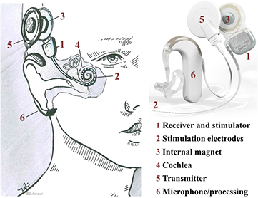
Figure 6. Components and implantation site of a CI system. A CI consists of a titanium housing containing the stimulator electronics (1). The stimulation electrodes (2) and a receiver coil with a magnet (3) in its centre are attached to the housing. These components are placed between the skull and skin just above the ear, from where the cable leads to the cochlea (4). An extra-corporal transmitter coil (5) attaches to the skin and aligns with the internal coil due to the second magnet in its centre. The audio processor (6) with a microphone converts sound into electrical stimulation signals which are transferred wirelessly across the skin to the implant. This transfer occurs between the two coils and also provides power to the implant (cochlear implant adapted from [56]).
Download figure:
Standard image High-resolution image3.1. CI in MRI—from contraindicated to suggested safety
In the late 1980s it was claimed that CIs, although approved by the FDA, are contraindicated to MRI for the simple reason that they contain a magnet [128]. Two years later, in vitro experiments verified strong torque, induced currents and device dysfunction when CIs were subjected to MRI [129]. A series of in vitro and cadaver studies followed, with the goal of finding MR conditions under which the prevailing CIs would no longer be contraindicated to MRI. As a first step, implants were studied without the internal magnet in place. Heating [70], force, torque, the generation of unintentional stimulation pulses, implant damage, and imaging artefacts, were investigated with the conclusion of acceptable compatibility at 1.5 T including a large safety margin [77]. When the internal magnets were left in place, similar findings were made for all aspects mentioned, except for torque, and significantly larger imaging artefacts. The magnet was found to exhibit a torque large enough to cause implant movement in some patients [11, 76]. Further detailed investigations in 2001 of the torque of CIs on the implant site, and the tissues countering the force, suggested safety for field strengths up to 1.5 T [14]. It was argued that the skull in which the CI is embedded can withstand much greater forces, except in infants [144]. The demagnetisation of internal magnets in MRI was studied, but no significant change was found [71], rebutting another device dysfunction modality. In vivo studies were first published in 1998 and 2001 at 1 T [72, 74], followed by a case report in 2003 at 1.5 T [66], all reporting no complications. These studies were carried out on the generation of CIs, which had the internal magnet inside the implant housing, rendering the magnet unremovable for MRI. As a consequence, the force and torque originating from the magnet was acting upon the housing as a whole.
After these studies, hardly any further attention was paid to implant dislocation, heating of electrodes, and unintentional stimulation in scientific publications—perhaps it was assumed that these problems had been solved? At the same time, a new generation of CIs was launched, in which the internal magnet was now located in a silicone pocket outside the housing to facilitate magnet removal prior to MRI examination, as a countermeasure for the large imaging artefacts suffered. However, magnet removal and reinsertion involves two surgical interventions, which is an aspect in favour of leaving the magnet in place. By placing the magnet into a silicone pocket outside the housing (figure 6), the main cause of interaction between CI and MRI was not eliminated but rather facilitated, and magnet dislocation became a frequent incident [5]. The dilemma of deciding between large imaging artefacts and potential magnet dislocation, versus the risk of two surgical interventions for magnet removal, is persistent [6, 26, 73, 145], and in both scenarios adverse events ensued (table 4).
Table 4. Compilation of MRI interaction studies for CI.
| Hazard/consequence for | |||||||
|---|---|---|---|---|---|---|---|
| Interaction | B0 | Study type | Patient | Implant | Diagnosis | Reference | |
| Cochlear implant | Artefact | 1.5 T | Patient | N/A | N/A | Artefacts | [66–68] |
| 3 T | Cadaver | N/A | N/A | Artefacts | [26, 69] | ||
| Force | 1.5 T | Patient | Mechanical stress |
Mechanical failure |
N/A | [20, 49] | |
| Cadaver | Mechanical stress |
Mechanical failure |
N/A | [5] | |||
| Phantom | Mechanical stress |
Demagnetisation | N/A | [18] | |||
| Patient with head wrap | Mechanical stress |
Mechanical failure |
N/A | [23, 27, 50, 51] | |||
| Heating | 1.5 T | Phantom | No effects | No effects | N/A | [70] | |
| Artefact, force | 0.2 T | Patient | No effects | No effects | Artefacts | [71] | |
| 1 T | Patient | No effects | No effects | Artefacts | [72] | ||
| 1.5 T | Cadaver | No effects | No demagnetisation | Artefacts | [71] | ||
| Patient | Mechanical stress |
Demagnetisation, Mechanical failure |
Artefacts | [3, 73] | |||
| Patient | Mechanical stress |
No effects | Artefacts | [7, 8] | |||
| 3 T | Phantom | Mechanical stress |
Mechanical failure |
Artefacts | [25] | ||
| Artefact, force, heating | 1 T | Patient, phantom | No effects | No effects | N/A | [74] | |
| Artefact, force, heating, induction | 0.3 T | Patient | No effects | No effects | Artefacts | [75] | |
| 0.3 T–1.5 T | Phantom | Mechanical stress |
Demagnetisation | Artefacts | [76] | ||
| 0.2 T–1.5 T | Phantom | safety limits at 1.5 T | safety limits at 1.5 T | Artefacts | [14] | ||
| 1.5 T | Phantom without magnet | No effects | No effects | Artefacts | [77] | ||
N/A = Not applicable
3.2. Adverse events related to CIs in MRI
Controversially, in the case of the aforementioned two surgical interventions for the purpose of magnet removal, it has been discussed whether or not wound healing after surgery may restrict the patient to wearing the external component of the CI system [3, 68]. More severe adverse events related to magnet removal include the occurrence of deteriorated blood circulation in the implant covering tissue and a skin flap infection, culminating in internal magnet extrusion [19]. Consequently, some medical centres prefer to leave the magnet in place during MRI.
3.2.1. Magnet dislocation in MRI.
The complication of moving magnets in MRI was foreseen. One group proposed simply applying a tight head wrap to grant extra stability to the internal magnet and thereby prevent magnet displacement during MRI. An accompanying cadaver study demonstrated 14 magnet displacements in 16 MRI scans when no external fixation was applied, and no magnet displacements when a head wrap was applied. The authors suggested distinguishing magnet displacement and canting, where canting refers to the magnet not traversing the lip of the silicone housing [5]. In the following, both are referred to as magnet dislocation. The procedure of applying a head wrap, as an educated guess, was adopted as a mandatory requirement in all CI manuals in the MRI guidelines of the major CI companies MED-EL®, Cochlear® and Advanced Bionics® [145–148].
It took until 2008 for the very first adverse event related to CI in MRI to be reported, where the authors carefully state the 'very rare event of magnet displacement during MRI scanning' even though the patient was wearing a head wrap [49]. Once the first report had been published, the attribute 'very rare' was challenged simply by the number of reports on MR-related magnet dislocations, which followed readily thereafter [3, 6, 19, 23, 27, 50, 51]. One elaborated example reports 12 MRI-related magnet dislocations [6]. Therein, magnet dislocation is described as a serious complication, which can lead to transdermal magnet extrusion or meningitis caused by the infection spreading along the implant. Regarding canting, one group proposed the application of gentle firm pressure over the scalp to bring the magnet back into place and thereby avert the need for surgical revision [3].
In 2015, the MED-EL Mi1200 Synchrony CI emerged with the distinctive feature of a freely rotating and laterally polarised internal magnet. It was claimed that therewith the problem of magnet dislocation and demagnetisation had been solved [26, 146]. As a result, the device was approved for MRI at 3 T with an internal magnet in situ.
3.2.2. Pain, discomfort and sedation.
Another aspect of CI recipients in MRI examinations which is gaining immensely in importance is pain and discomfort, which has been explicitly mentioned as a concern only recently [3, 6, 19–26].
For instance, it was reported that 5 out of 18 CI recipients entering MRI were unable to complete the indicated MRI scans due to pain, although only one of them experienced magnet dislocation. In addition, yet another patient in this study had already experienced discomfort merely by approaching the MRI scanner [27]. Sedation was mentioned as a self-evident counter measure to discomfort and pain in some reports [8, 27], and additionally an anxiolytic was provided at request [3]. By contrast, Medtronic® recommend not to sedate in their manual for physicians concerning MRI examinations in DBS recipients, so that they can provide feedback about any problems occurring during the examination [149].
3.2.3. Imaging artefacts.
Besides the magnet displacement risk, internal magnets also cause major imaging artefacts (as explained in section 2.3.4) [11, 14, 21, 26, 69, 73, 75]. This compromises the diagnostic value of the imaging procedure, where the extent of the image disturbance depends on the MRI sequence used. Commonly used sequences can show circular signal voids with a radius of up to 8 cm from the centre of the implant [26]. Assuming the signal void resembles a sphere, and a quarter of the artefact is inside the head, the obscured volume would equal approximately half a litre, which equals one third of the average human brain volume and is illustrated in figure 4(H). However, it is worth noting that the MR image still features imaging artefacts after magnet removal due to the implant housing and its electronics. Thus limited diagnostic value in the vicinity of the implant is still to be expected [68].
3.3. Discussion of adverse events related to CIs in MRI
It could be argued that the surgical intervention necessary to readjust magnet dislocation is equal to reinserting the magnet after removal. However, intentional surgical intervention may be preferable, especially when it prevents discomfort and pain. How likely is the occurrence of magnet dislocation?
3.3.1. Probability of magnet dislocation.
It has been claimed that the risk involved when surgically removing and replacing the magnet for scanning is higher than magnet dislocation [8]. This may be true if the probability of magnet dislocation related to MRI in a CI recipient is 0.59 % as assessed here: [6]. This value is derived from 12 dislocations, which occurred in a collective of 2027 CI recipients over the time span of more than a decade. However, CI patients were only allowed to undergo MRI examinations in the last four years of the mentioned time span, and the number needed for a meaningful probability assessment of CI patients who underwent MRI examination was not reported. Therefore, the derived probability of 0.59 % for magnet dislocations among all implanted CIs should not be taken as the correct value for the probability of adverse events in MRI procedures. In the same study, a total of three CI patients underwent MRI between January and May of 2013. If one extrapolates this number to the above mentioned period of four years, one can assume that around 29 of the 2027 CI patients underwent MRI. This rough estimate puts the probability of MRI-related magnet dislocation in CI recipients up to more than 40 % (12 out of 29). Others state a risk of up to 15 % even with head wrap application [3]. So how can the likelihood of magnet dislocation be diminished?
3.3.2. Head wrap.
Since Gubbels et al proposed the head wrap technique in 2006, it has become a strict requirement during the MRI examinations of CI recipients at field strengths higher than 0.3 T. This is in spite of several reports on adverse events occurring with the application of head wraps. Furthermore, Gubbels and co-workers suggested characterising the amount of necessary pressure applied by a head wrap to prevent magnet dislocation. To our knowledge, no such study has ever been published. The data from the initial cadaver study did not seem to have been verified nor systematically investigated against the hypothesis that a correlation between magnet dislocation prevention and the application of a head wrap exists. The magnetic field strength, however, has increased in clinical practice from 0.3 T over 1.5 T to 3.0 T, and exerts a force that is proportional to it, as explained in section 2.3.2. Let us estimate the forces exerted by a head wrap necessary to prevent magnet dislocation. In a study on the MRI-induced torque of a typical internal CI magnet, a magnet 12 mm in diameter was investigated, exhibiting a torque of 0.2 Nm in a 1.5 T MRI scanner [18]. This means that a force of 33 N applied to the rim of the magnet is necessary to counteract the torque and therefore prevent magnet movement. In other words, an equivalent of 3.3 kg weight has to be applied to the edge of the magnet to prevent it from moving when exposed to a 1.5 T MRI scanner. Without a head wrap, this task is left to the silicone pocket in which the magnet is contained, together with the surrounding tissue. Assuming that it is sufficient to apply this weight, not on the edge of the magnet but on an area of one cm2 over the scalp, the necessary pressure to counter the magnet torque is equivalent to 3.3 bar or 3.3 kg cm−2. When choosing to apply this pressure with a head wrap, every cm2 covered with the head wrap must experience the same amount of pressure. For example, a 10 cm wide head wrap, as proposed in a Cochlear® CI manual [145], bound around a head with a 60 cm circumference and providing a load of 3.3 kg cm−2 would result in a total load of about 2 tons. Instead, a stiff piece of wood with a plane surface and dimensions of e.g.  cm3 placed between the head wrap and the scalp directly above the magnet would be better suited. The idea proposed herewith of using a splint is not new. However, folded paper, plastic cards [19] or moulds [8] would either not be stiff enough, or still apply pressure to the whole scalp surface, instead of only where the magnet is situated underneath, therefore not serving the purpose that a splint should. Nevertheless, the principle of these methods was adopted in some manufacturer's manuals in 2012 [6, 145].
3.3.3. Concerning regulations of CI in MRI.
If a CI recipient is scheduled for an MRI exam, it is of paramount importance to be aware of the manufacturer's model-specific MRI recommendations. All companies instruct users to remove external components prior to MRI examination. How are CIs finally evaluated with respect to their risk-benefit-assessment in MRI? Unambiguous statements are rare. One review about the MRI safety of CIs concludes that MRI in 3 T scanners is generally considered unsafe, and that 1.5 T MRI is contraindicated for CI recipients unless the MRI indication outweighs the risks of MRI examination [22]. This statement raises two important points. First, some current CIs are certified according to regulations as MR-conditional with the magnet in place for 1.5 T, and for 3.0 T without the magnet. One is even certified MR-safe for 3.0 T with the magnet in place. Consequently, the statement of 'generally considered unsafe (3 T) or contraindicated (1.5 T)' is no longer valid. However, Cochlear® advises magnet removal before every MRI procedure on CI recipients [145]. MED-EL® propagates safe MR procedures in CI recipients with the magnet in situ, but a supportive head wrap must be placed over the implant. Furthermore, they point out that performing an MRI without a head wrap could result in pain in the implant area [145, 146]. These recommendations stand in contrast to the reports on the adverse events mentioned earlier. Secondly, most reported cases of MRI indication in CI recipients are due to severe, often life-threatening medical conditions such as NFII, brain tumours, potential breast cancer, etc [3, 8, 27, 49, 51, 66, 67, 143]. It is argued that the MRI indication outweighs the risk of MRI examination. To this effect, MRI in CI recipients can be considered safe enough to proceed with the imaging of severe indications. However, the chance of harm, discomfort, pain and the risk of inflammation either by magnet dislocation or surgery is so high that MRI in non-life-threatening indications of CI recipients does not appear to be performed. Should a CI recipient be able to undergo MRI to diagnose a rupture of the anterior cruciate ligament [27]? This could be a starting point for a debate on where the threshold for taking the risk of an MRI examination is, and how we can provide access to MRI for every neural implant recipient, so that the treatment of a disease does not restrict the diagnosis and treatment of another.
3.4. Concluding remarks on CI in MRI
CI treatment does not require postoperative MRI. However, imaging due to diagnostic needs independent of the hearing loss preceding CI implantation may occur, and in NFII frequent MRI monitoring is indicated. Most adverse events related to CI in MRI occur due to the exertion of force onto the implanted magnet, which causes it to move. The resulting pain and discomfort discourages patients and physicians from performing imaging in non-severe indications, despite the legal declaration of 'MR-conditional' CIs. The suggested countermeasure of a head wrap is an inefficient, unpleasant, non-scientific and unproven remedy for magnet dislocation. Detailed reporting on pain and the discomfort of CI patients in MRI can be considered a valuable step away from the achievement of pure objective feasibility and towards a patient-oriented mindset. The invention of a rotating magnet (MED-EL Mi1200 Synchrony) resulted in a big leap towards the 'MR safety' of the device, and it is a promising step in the reduction of torque and therewith the magnet dislocation, pain and discomfort of CI patients in MRI. It is these kinds of industry-driven technical innovations that make MRI more accessible for CI recipients. It must be noted, however, that the development and especially the approval process in this specific case took at least six years. Measures such as the head wrap are at most an illusion to overcome such long waiting periods for the approval of bio-medical product innovation by the regulatory body.
4. Deep brain stimulation implants and MRI
DBS is a successful medical therapy which has been applied in more than 75 000 patients [37] to treat the symptoms of Parkinson's disease (PD), for which implantable pulse generators and electrodes have gained medical device approval. The treatment has also been successfully applied to dystonia, essential tremors, Tourette syndrome [151], epilepsy, obsessive compulsive disorder [82] as well as other movement disorders and psychiatric diseases [152], which have been investigated in many clinical trials. The underlying principle of DBS implant systems, as shown in figure 7, is the modulation of brain activity by the electrical stimulation of target structures in the brain, such as the subthalamic nucleus, or the globus pallidus internus, and has replaced lesional neurosurgery [153].
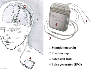
Figure 7. An implantable DBS system consists of four components: the stimulation probe (1), fastened in the skull by a fixation cap (2), an extension lead (3), and an implantable pulse generator (4). The stimulation probe is 1.27 mm in diameter and consists of approximately 40 cm long flexible tubing containing wires that are connected to the so-called active sites. These active sites are metal contacts interfacing the electrical components with the target tissue. The extension lead connects the probe wires to the implantable pulse generator, and is available in various lengths. Finally, the implantable pulse generator holds the electronic circuitry and a battery in a hermetic titanium housing, with dimensions on the order of  cm3. Due to the lack of space in the head, pulse generators are implanted into a pocket under the collar bone or in the abdomen, which explains the large range of available extension lead lengths [150] (DBS adapted from [55]).
Download figure:
Standard image High-resolution image
DBS probes are implanted with high precision by stereotactic surgery through a burr hole in the skull, targeting structures the size of a cubic centimetre [154]. Once the electrode is in position, electrical stimulation trials are used to verify treatment efficiency at the specific electrode position. Before the final steps of pulse generator implantation and the connection of the latter to the DBS probe using extension leads, it is essential to verify the electrode contact position by imaging [47]. Despite the hazards involved when exposing a patient with DBS hardware to MRI, MRI is considered the gold standard for electrode localisation [32]. In a few cases, the implantation procedure is guided by intraoperative MRI, where the entire surgical procedure is performed with the patient inside the 1.5 T scanner, and thus multiple examinations can be performed to monitor the probe positioning and any surgical complications [155].
4.1. Paradigm changes in DBS: from MR-unsafe to MR-conditional
Initially, DBS systems were contraindicated to MRI. Hence, the behaviour of implanted pulse generators was investigated during MRI with a focus on induced voltages and the heating of the housing [88]. Further experiments (overview in table 5) in vitro were followed by the in vivo examinations of 38 patients in the late 1990s with activated devices [89]. At the same time, the first in vivo fMRI studies with DBS patients were conducted [12, 138], showing considerable potential for better understanding of the mechanisms underlying movement disorders in PD. A warning on the potential for excessive heating when DBS probes undergo MRI was announced in 1999 [12]. Three years later, this phenomenon was quantified in an in vitro study, in which the temperature increase of 2.3 °C at the electrode tips was assessed as 'physiologically inconsequential'. However, a temperature increase of up to 25.3 °C was measured when a body coil instead of a head coil was used [80]. In 2004, it was found that depending on the experimental setup, heating can occur with a 15.6 °C temperature increase at the electrode and a 59.1 °C increase at the phantom surface [90]. Another study published in 2007 found only minor changes in an in vitro experiment with a temperature increase of 0.59 °C to 1.36 °C at the electrode tip when the stimulation was activated during fMRI. The temperature increase of the electrode in fMRI was higher at 1.5 T than at 3 T during an in vitro safety study [17]. In 2013, a Medtronic® DBS implant system was labelled 'MR-conditional' and was allowed to undergo MRI if the device was in the 0 V setting and then set to off, with application of the transmit and receive RF head coil only, and with a 0.1 W kg−1 SAR limit in the head.
Table 5. Compilation of MRI interaction studies for DBS.
| Hazard/consequence for | |||||||
|---|---|---|---|---|---|---|---|
| Interaction | B0 | Study type | Patient | Implant | Diagnosis | Reference | |
| Deep brain stimulation | Artefact | 1.5 T | Patient, Phantom | N/A | N/A | Electrodes obscured | [63] |
| Patient | N/A | N/A | Correct | [78] | |||
| positioning | |||||||
| Heating | N/A | Animal | Safety level | N/A | N/A | [79] | |
| max. 43 °C for 30 min | |||||||
| 1.5 T | Phantom | Excessive heating | N/A | N/A | [80, 81] | ||
| Phantom | Moderate heating | N/A | N/A | [82] | |||
| Sequence | No effects | N/A | Improved | [83] | |||
| development | image | ||||||
| Simulation | SAR hotspots | N/A | N/A | [84] | |||
| Phantom | ΔT = 0.79 °C @ 0.2 W kg−1 | N/A | N/A | [85] | |||
| 1.5 T, | Phantom | ΔT = 10.3 °C | N/A | N/A | [86] | ||
| 3 T | |||||||
| 3 T | Phantom | ΔT = 1.44 °C @ 0.2 W kg−1 | N/A | N/A | [85] | ||
| Phantom | ΔT = 2.3 °C @ 2.9 W kg−1 | N/A | N/A | [87] | |||
| Animal, Simulation | Excessive heating | N/A | N/A | [63] | |||
| Induction | 3 T | Phantom | N/A | no effects | N/A | [85] | |
| Heating, induction | 3 T | Phantom | Moderate heating | No external stimulus | N/A | [17] | |
| Force, heating, | 0.35 T - | Phantom | Excessive heating | Stimulus disfunction | N/A | [88] | |
| Induction | 1.5 T | ||||||
| 0.2 T - | Phantom | No heating | Stimulus disfunction | N/A | [89] | ||
| 1.5 T | |||||||
| Artefact, force, | 0.2 T - | Patient | Pain (stimulation) | Reed switch activation | Minor artefacts | [89] | |
| Heating, induction | 1.5 T | ||||||
| 1.5 T | Phantom | Excessive heating | Stimulus disfunction | Minor artefacts | [90] | ||
N/A = Not applicable.
4.1.1. Adverse events related to DBS hardware in MRI.
The first adverse event with DBS hardware related to MRI was reported in 2003, when a patient underwent MRI prior to pulse generator implantation with two unconnected, implanted electrode leads fixed outside the RF head coil in a straightened manner. The patient experienced transient focal dystonia and ballism immediately after MRI [30]. Two years later, a different DBS patient underwent MRI seven months after pulse generator implantation. The employment of an RF body coil had caused hemiparesis, which was observed upon the patient exiting the MR scanner. After the imaging procedure, a haemorrhage surrounding one of the two implanted probes was found. According to the authors, all the body-averaged SAR values ranged from 0.57 to 1.26 W kg−1 with local SAR values of up to 3.92 W kg−1 [31]. Consequently, the reported exceeding of limits resulted in responses within the community reminding responsible staff to follow the manufacturers' recommendations [156]. No incidents were reported throughout the next six years except for the failure of two pulse generators during the MRI procedures [151, 157]. In 2011, a case report on dyskinesia and tremor during a postoperative MRI procedure was published [32]. The scanning had to be aborted, however, no abnormalities could be found in the MR image. A second, non-stereotactic MRI was performed on the second postoperative day before pulse generator implantation. This imaging procedure revealed hyperintensities along the whole length of both electrode leads, suggesting oedema, which, according to the publication, was associated with patient movement during the first MRI scan [32]. A different case also reported hyperintense images observed in an MRI scan on an electrode lead 12 months after implantation, where the lead was connected to its pulse generator. The reporting authors assumed that the observed hyperintense signal was an oedema caused by MR-related heating, as the electrode had not been manipulated manually [37]. Similar hyperintensities around DBS probes were reported in other retrospective studies, but their correlation to MRI has not been determined [36, 38, 158].
4.2. Efforts to reduce heating
As all reported adverse events are related to heating, we focus on this prime concern, and discuss several strategies to reduce heating in the following. Can MRI be replaced by CT in some cases?
4.2.1. DBS probe localisation using CT—an alternative to MRI?
Precise electrode positioning is crucial for therapeutic success, and avoids the need for additional surgery for later repositioning [157, 159, 160]. The postoperational probe localisation procedure, therefore, is essential. One way of replacing MRI with electrode localisation is the image fusion of preoperative MRI with a postoperative CT image. It is beneficial that the imaging artefacts caused by the electrode were claimed to be smaller in CT than in MRI, resulting in a more precise image [161]. Consequently, image fusion was declared to be a safe and fast technique for the postoperative assessment of the DBS electrode position [153]. A disadvantage of the fusion technique is that morphological information about the targeted tissue is lost and postoperative complications, such as haemorrhage or infarction [161], are much less distinct. Besides, the patient is exposed to ionising radiation and the image fusion may be impaired by a brain shift related to DBS implantation, causing tissue shifts of up to 4 mm [162]. As explained in section 2.3.4, the DBS electrode is disguised in the MR image by an imaging artefact. This artefact is larger than the dimensions of the active sites [163] and has led to significant discrepancies compared to brain CT [159]. It is known that the electrode position is eccentric to the imaging artefact [96, 161]. Yet, despite the MR artefacts, several studies comparing CT and MRI electrode localisation procedures conclude that MRI is a precise modality [78, 161, 163, 164]. MRI holds the advantage of superior diagnostic value in the identification of pathological abnormalities related (e.g. haemorrhage) or unrelated to DBS, such as tumour and stroke [82]. Therefore, it is desirable to perform MRI if patients exhibit poor or worsening outcomes of the stimulation treatment. In particular, MRI is often used in patients who undergo the implantation of an additional electrode, or reimplantation for more effective treatment [81]. Furthermore, great interest exists in combining DBS with fMRI [17, 165] to acquire more data and a deeper understanding of the brain. For these reasons, many groups rely on MRI for the position verification of DBS probes [32, 157, 163], despite the risk of severe heating of the DBS hardware in MRI [79].
4.2.2. Heating of DBS hardware in MRI
As illustrated in figure 7, the tip of the DBS electrode sits in a most delicate location. Therefore, the MRI-related heating of DBS probes requires particular attention, since the sensitivity of the brain to temperature increase is also paired with no opportunity to sense it. Although tissue in the central nervous system can endure 43 °C for 30 minutes [79], it is strictly recommended by regulatory bodies not to exceed a 1 °C temperature increase.
4.2.3. SAR and its restriction
There is a high correlation between the SAR and heating at DBS electrode tips [82]. Therefore, the field strength of scanners and the SAR in conjunction with DBS hardware is restricted to 1.5 T and 0.1 W kg−1, respectively. According to clinicians, this upper SAR limit is extremely low and limits the range of sequences which can be applied to a point of crucial impracticality [33, 166]. In contrast, studies at 3 T show the electrode lead tip temperature exceeding the limits of regulations [85, 87] and thus confirming the purpose of the SAR limit. Recent manufacturer adaptations allow less conservative settings [47].
The level of SAR applied during MRI is controlled by the MR scanner operator via the machine console and software. However, it has been revealed that large discrepancies exist between the displayed SAR and the actual SAR deposited by the scanner between manufacturers, scanners of the same manufacturer and even between software versions run on a single machine [81, 167]. Mostly, the deposited SAR is overestimated—in some cases by as much as 2.2-fold—which represents a conservative setting. Nonetheless, incorrect SAR monitoring can inappropriately restrict MRI scans even further and may hinder clinical scanning and pulse sequence development. In particular, these restrictions can entail trade-offs in the image acquisition time and spatial resolution, and therewith limit diagnostic utility [168]. Finally, it is crucially important to precisely manage the total power deposition for the safety evaluation of conducting MRI with implantable components.
4.2.4. Simulation of SAR and implant-related heating
Heating and the implant-correlated heating of all kinds of implants are problems that have been tackled in many studies [82, 169–174]. The major present-day challenge is the handling of the wave characteristics of the RF pulses, which makes it difficult to provide general solutions to the problem. Each case depends strongly on the geometry of the MR system, the patient, the implant and the scanning parameters. Furthermore, the position and orientation of the implant and the patient with respect to the electromagnetic fields has a great influence as well. Thus, it is challenging to derive general solutions for MR safety. An interlaboratory comparison study has pointed out widely varying results among groups evaluating the heating of implants, despite following current guidelines [84], in agreement with the aforementioned challenges. Consequently, implants have to be tested for individual scanning parameters and MR units. This, as well as the numerous influencing parameters, have made experimental work tedious, and a useful outcome remains rare. Therefore, simulations are currently used to compute the distribution of the electromagnetic fields and SAR hot-spots (see ISO/TS clause 10 [57]). As a result, the evaluation of implant heating in MRI using simulation software has become an indispensable tool [84, 175, 176].
4.2.5. What physicians can do
Device manuals usually provide clear recommendations about whether and how MRI can be conducted safely. It is important to be aware of the influence the condition of a device can have on its heating behaviour. Some devices have special MRI modes, others should be turned off during examination. The condition of leads—e.g. whether they are externalised—has a tremendous influence on their heating behaviour, and the manufacturers' recommendations should be strictly met. Specifically in the case of DBS, it has been shown that the way probes are implanted strongly influences the heating characteristics during MRI. This mainly affects the excess lead management, where concentric loops in the axial plane around the burr hole may reduce heating [86]. The excess extension lead should be coiled around the perimeter of the pulse generator [177]. Furthermore, the use of a head transmit/receive coil dramatically reduces electrode tip heating when compared to body coils. This is because the pulse generator and a portion of the extension lead is outside RF exposure, which results in less induced current and consequently in less heating [80]. Sequence selection and development can make a contribution to the reduction of heating. Sarkar et al developed an alternative to spin-echo sequences which has been useful for MR-guided DBS procedures [83]. The presented short tau inversion recovery sequence features ultra low SAR while still providing adequate tissue contrast in the brain tissue of DBS recipients. However, the sequence exceeded approved limits once patients had been fully implanted [83].
4.2.6. What manufacturers can do
Corporate research has led to technical innovations that address the multiparametric effects of heating from several technical aspects. For one, it has been shown that coiling wires can reduce the occurrence of heating significantly compared to straight wires [140]. Medtronic® advanced this by introducing a braided body that acts as an RF shield and a dissipation surface for leads to reduce heating. In vitro experiments show how the temperature increase is distributed over the whole lead length rather than concentrated at the electrode tips [178]. Another approach to reducing implant heating by making adjustments on the scanner side involves the design of implant-friendly RF coils [179].
4.3. Discussion: How likely are adverse events of DBS hardware in MRI?
How safe is MRI for patients with implanted DBS hardware? The probability of MRI-related adverse events is claimed to be 1 out of 4000 [32]. Considering the total number of DBS patients, the number of reported MRI-related adverse events is surprisingly low, especially since many centres deliberately employ significantly higher SAR levels than recommended [32–35]. It is worth comparing the few published MR-related adverse events to the report on common complications during DBS implantation procedures. Non-MRI-related adverse events in DBS implantation state haemorrhage, electrode malposition, electrode fracture, electrode migration, pulse generator infection and multiple reversible psychiatric symptoms, all within a collective of 55 patients [180]. Therefore, it is understandable when the risk of MRI in DBS recipients is considered 'certainly less than the risk of implantation' [32]. This seems a valid argument for the MRI procedure as part of the implantation; however, for later monitoring the risk should be reevaluated, especially since the probes are then connected to the pulse generator, which represents a modified cable configuration during implantation. It is intriguing that despite these low rates of incidence, the topic still draws great attention. This could be due to the fact that incidents can be severe. Another explanation, however, could be the high rate of complications associated with the DBS procedure itself. It would be challenging to relate incidences directly to MRI as it is usually performed between surgeries and is hence documented elsewhere. While adverse events after DBS placement such as haemorrhage, infection, or hardware-related complications are common [158], several groups have reported on a hyperintense MRI signal around DBS probes which is assumed to be an oedema, and has been observed, in most cases, three or more days after surgery [32, 36, 38, 158]. Two reports state a total of 23 such observed hyperintensities, stating that the nature and aetiology of the phenomenon remains obscure [36, 158]. The origin of these signals could be inflammatory tissue response [36] or an oedema around the probes [37]. Whether these oedema are caused by implantation or are MRI-related remains unclear [38].
4.4. Concluding remarks on the effects of MRI on DBS hardware
Electrode position verification by MRI is invaluable to the outcome of the DBS implantation procedure. The imaging procedure entails the risk of MRI-related heating of the implanted DBS leads, which has resulted in severe injuries of the targeted brain tissue in the past. Heating constitutes the largest MRI-related threat to DBS patients. Its complex physical nature makes prediction hard, and thus highly restrictive precautions have been imposed. The rule of thumb in which heating occurs at lead lengths matching the integer fractions of the RF wavelength is insufficient. MRI-related adverse events are reported far less than implantation-related complications. However, since there is no continuous monitoring or imaging available, some MRI-related adverse events might have been missed, or their cause misinterpreted.
5. Established and emerging applications of neural implants
Several applications of neural implants have been established and approved beyond cochlear and DBS implants. Intracranial electroencephalogram (icEEG) and grid arrays for electrocorticography (ECoG) are invasive tools in the diagnosis of severe neurological diseases. Paddle electrodes interface nerves in the neuromodulation of more than 130 000 patients with SCS to alleviate chronic idiopathic pain and treat urge incontinence. They have also been introduced in closed loop epilepsy implants recently. Miniaturised implants benefit from micromachining technologies that combine mechanical, optical and electronic features in micro(opto)electromechanical systems (M(O)EMS). They have shown first clinical application in retinal implants to restore vision and promise new treatments in neurological rehabilitation [181] and bioelectronic medicine [182, 183]. While the design principle, size and materials used are mostly the same in the approved medical implants as in the already discussed applications, the new miniaturised implants are much smaller in size, and come with different materials and manufacturing technologies, as well as with novel implantation procedures and sites. How can knowledge be transferred from experience with the established implants? And do new challenges occur with these miniaturised implants? First, we summarise our knowledge on the established applications and then we share our preliminary knowledge on miniaturised neural implants.
5.1. Arrays for intracranial EEG
IcEEG is an invasive diagnosis method to record electrical brain activity. It is often applied in patients with drug-resistant temporal lobe epilepsy. The grid arrays are implanted in presurgical epilepsy monitoring to combine electrical information about the seizure onset zone, with MRI imaging to plan and guide the surgical removal of the affected brain area as a therapeutical intervention. The major limitation of the recording method is its limited spatial resolution, which can be solved by the simultaneous icEEG and fMRI recording of BOLD signals [184]. In addition, the localisation of the electrodes with respect to the individual anatomy is done with MRI [185]. The combination of icEEG implants in MRI was considered 'risk free' when MRI was first performed in 50 icEEG patients to confirm electrode placement. Furthermore, better electrode placement and fewer incidents were reported when employing an MRI guided method [186]. Later, others found that stainless steel grids exhibited torque during ex vivo experiments [187]. Patients with platinum iridium alloy grids experienced no adverse events. The artefacts of such alloy grids were more localised than those of stainless steel grids and therefore provided better localisation of the electrode sites and recognition of postoperative complications. However, platinum-iridium is very expensive and thus most grids are still steel-based. The safe localisation of intracranial electrodes by MRI was concluded in a retrospective study [188] after 108 in vivo MRI scans. No significant temperature increase was found in the grid electrodes used for epilepsy monitoring in high-resolution MRI [189] and in hybrid icEEG electrodes [190]. However, combining fMRI and icEEG resulted in a significant temperature increase of up to 6.9 °C with strong dependencies on the RF coil placement and MRI sequence, as well as on cable length and orientation due to implantation procedure. As a result of the study, the authors provided safety recommendations for MRI at 1.5 T and 3 T, considering force, unintentional stimulation and temperature change [191, 192]. Following these recommendations, two epilepsy patients underwent icEEG in 1.5 T fMRI. The icEEG signal was comparable to recordings outside the scanner and the measurements allowed the study of the whole human brain epileptic network without adverse events [193]. A combination of icEEG and fMRI in a 3 T scanner resulted in a temperature increase in vitro of 10 °C when running sequences with a high SAR, but considered the risk as low when following protocols strictly. Artefacts occurred up to 20 mm from the electrodes [194]. Combined icEEG-fMRI investigations were considered useful, but only a small number of patients underwent invasive evaluation prior to surgery. Besides the direct benefit as a clinical investigation tool, the method holds great promise in the investigation of the relevant scientific questions [195]. Technological developments are able to reduce hazards to the patient. Polymer-based conductors and carbon-based electrode sites showed reduction in heating and imaging artefacts in CT as well as in MRI in a pilot study [196].
5.2. Paddle electrodes for neuromodulation
Paddle electrodes are commonly used for spinal cord and peripheral nerve stimulation to treat chronic back or leg pain. Applications in the brain include epilepsy monitoring, and when placed parallel to the central sulcus, the motor cortex can be stimulated, allowing the treatment of extensive pain [197]. A flat paddle shape with three to four contacts showed no risk or side effects. An in vitro risk assessment study of paddle electrodes in MRI found an insignificant temperature increase, induced voltages up to 6 V, no mechanical forces and artefacts 1 cm in length and 3 mm in height [198]. The RNS implant of Neuropace® is the first closed-loop epilepsy neuromodulation system, which means it detects unusual activity and disrupts it by electrical stimulation treatment in situ on demand. The implant combines paddle electrodes with depth electrodes. These electrodes are connected to a titanium housing integrated in the skull via a short cable. The system is currently labelled MR unsafe.
5.3. Retina implants
Retina implants restore vision in patients suffering from blindness caused by degenerative diseases such as retinitis pigmentosa, or age-related macula degeneration. In these diseases, the light-sensitive rod and cone cells degenerate, while part of the retinal network and the ganglion cells that form the optic nerve remain intact. So far, these implants have been able to restore basic sight [199–201]. Approved medical devices have been developed by three companies worldwide: second sight with its ARGUS II in the USA, Retina Implant with its IMS-Alpha and AMS-alpha systems in Germany, and Pixium Vision with their Iris II system in France. Other groups around the world have also conducted clinical trials in a few humans [202], but the majority of patients (about 100 in 2014 [199]) are being treated with approved medical devices. The Argus II retina implant was studied in vitro for guidelines and conditions to permit safe use in MRI, resulting in an MR-conditional certificate at 1.5 T and 3 T [203]. The cohort size suggests an exploratory phase for this medically approved implant, and therefore MRI scans with the implant are reasoned as part of routine medical care [199] as well as for unrelated retina implant purposes such as tinnitus basal tongue tumours. So far, no adverse effects have been reported [204].
5.4. Miniaturised micromachined neural implants
Promises and high expectations drive the development effort behind miniaturised systems for neural implants and electroceuticals [182]. The only approved medical application worldwide in which micromachined components play a significant role is currently the ALPHA-IMS/ALPHA-AMS retina implant. However, micromachined needle probes have become state of the art for fundamental neuroscientific research to investigate the brain [205]. A silicon-based needle array (Blackrock, Salt Lake City, Utah, USA) has also achieved medical device approval (PMA) for treatment up to 30 days. It can be used chronically in clinical trials (IDE), with permission from the FDA (USA) for implantation as a brain–computer interface to control assistive devices [206, 207]. Fundamental studies with silicon-based brain probes have been performed to investigate image artefacts when using fixation screws for percutaneous head-mounts [94], but without having to meet the requirements of international MRI safety standards.
How will the MRI interact with these small implants in the brain? The heating and induction of voltages might follow a similar pattern to that observed in larger implants. Force interaction due to the static B0 and dynamic RF fields might result in different outcomes, since the material thickness of contact sites is vanishingly small—as is the moment of inertia—when compared to cochlear and DBS implants. RF fields might induce dynamic loads on the implants, from which technical failure of the electrode-substrate compound can proceed. Probes can start to vibrate during RF excitation and thereby damage the surrounding tissue. A look at the interaction between implants and tissues (outside MRI) reveals that micromotion plays a large role in long-term communication stability, as pointed out in the review of Gilletti et al [208] and Prodanov et al [209].
What will MRI-probe–tissue interaction look like in different field strengths and under different sequences? Can lateral movement with a minor amplitude and an overlaid gradient-induced torque lead to strong lateral displacement? [210]. Can minor amplitude vibrations induced by gradient-induced torque lead to strong translational displacement of the electrode? Answers to these questions might be even more interesting since it is not clear how an electrode should be mechanically fixed within the brain. Electrodes that are not fixed to the skull lead to less respiration and pulse-induced movement [209]. The advantages of micromachining technologies lie, for example, in the vanishing thickness of the metallisation of electrodes. Reducing the volume of the amount of metal [211], as well as applying materials with matched susceptibility [95], reduces imaging artefacts significantly and offers imaging information from areas close to the implant. Since micromachined components are of the size of MRI resolution and below, it is questionable whether current standards offer sufficient tests to evaluate the interaction between implant and tissue during an MRI scan, and assess whether an implant is MR safe or not.
6. Discussion and conclusion
Future trends will increase the need for care within the MRI environment. For example, new generations of MR scanners promise a higher static field strength beyond 3 T. It is worth noting that the RF power necessary for excitation increases quadratically with increasing static magnetic field strength, when other sequence parameters are kept constant [168], which obviously increases the SAR levels a patient would be exposed to. Another important aspect is the increase of RF frequency which accompanies stronger static magnetic fields. The inversely proportional shorter wavelength could become troublesome in conjunction with smaller device lengths due to the inadvertent resonance phenomenon, as pointed out in section 2.3.3, which may become more likely. In this context, the trend towards multichannel parallel transmission MRI systems should also be kept in mind, as the summation of short-wavelength electric fields is more likely and may result in underestimation of the RF heating levels [212].
Non-invasive MRI is currently the most important modality for diagnostic brain imaging. Clinicians and patients have accepted neural implants as a valuable treatment method for neurological brain ailments such as stroke, Parkinson's and Alzheimer's disease. Furthermore, the method is growing in importance as we are facing an ageing society. Inevitably, the compatibility of these medical devices with MRI has turned into a distinctive product safety and acceptance issue, with a direct effect on sales as well. The question as to whether patients with brain implants should undergo MRI is thus of growing importance. Currently, the question is posed daily—with regard to every patient and their individual circumstances—concerning implant type, the available MR scanner, and a feasible pulse sequence routine. Engineers and physicists can provide many of the answers, however, often these are too complex to be useful in the daily hospital routine. Recommendations for implant manufacturers are also not easily made, as many implant materials are chosen to satisfy requirements other than MRI performance. However, a set of basic conclusions can guide physicians and implant manufacturers through risk analysis and management in device design as well as MR imaging:
Physicians or MR users:
- Classify active implants in MRI as a serious hazard.
- Train staff in the complex matter thoroughly.
- Stay up to date with manufacturers' recommendations.
- Council patients comprehensively.
Implant manufacturers:
- Avoid any ferromagnetic materials.
- Use only short cables.
- Consider that implant heating is affected by numerous factors, such as the implant itself (location, geometry, electronics), the MR hardware (especially the choice of RF frequency), and the MR pulse sequence.
- Use materials with magnetic susceptibilities as close as possible to those of the average tissue values.
- Reduce implanted metal volume to a minimum.
- In particular, note that some technical choices are valid under transfer from low to higher B0-fields, or from one implant type to another, but many are not.
An easy-to-follow standard operating procedure is therefore still lacking and needs to be derived. This will require the device manufacturing companies, who have to cope with liability issues, and the medical personnel, who directly experience adverse patient events under their care, to find a common language with which to share their experience, in order to establish adequate solutions for the benefit of the patient. Therefore, until we can answer our initial question cooperatively with a confident 'sure', we should insist on a 'yes, but:'.
Acknowledgment
We are grateful for the graphical artwork contributed by Danesh Ashouri. This work was financially supported by the BrainLinks-BrainTools Cluster of Excellence—funded by the German Research Foundation (DFG, grant number EXC 1086) as well as by the European Research Council (senior grant no. 290586 'NMCEL').
Footnotes
- a
Mechanical stress includes pain and discomfort.
- b
Mechanical failure in CI is mainly due to magnet dislocation.