


Abstract
Time transfer using global navigation satellite system (GNSS) is a primary method of remote atomic clock comparisons. As of today, there are four operational GNSS systems, namely GPS, GLONASS, Galileo and BeiDou Navigation Satellite System (BDS or BeiDou). All of them can continuously provide position, navigation and time services. This paper mainly focuses on the progress of BeiDou time transfer at the National Time Service Center, Chinese Academy of Sciences (NTSC). In order to realize the BeiDou common view (CV) time comparison, we developed the Rinex2CGGTTS software according to the guidelines of the Common GNSS Generic Time Transfer Standard, Version 2E (CGGTTS V2E). By comparing the solutions of the Rinex2CGGTTS software to the solutions of the sbf2cggtts software provided by the manufacturer of our multi-GNSS receiver, we found the sbf2cggtts (version 1.0.5) solutions contained biases in measurements to different BeiDou satellites. The biases are most likely caused by sbf2cggtts' timing group delay corrections in data processing. The noise of the observation data is analyzed by code multipath and common clock difference. Finally, the BeiDou CV results are compared to the GPS/GLONASS/Galileo CV results between NTSC and three European UTC(k) laboratories, including Royal Observatory of Belgium (ORB), Real Institute y Observatory de la Armada (ROA), Research Institutes of Sweden (RISE or SP). For the comparisons of each baseline, we aligned the BeiDou/Galileo/GLONASS links to the calibrated GPS link with the double-difference method. The results show that the performance of BeiDou CV is correlated to the number of BeiDou satellites available in common view. With the current BeiDou constellation, the standard deviation of the differences between all BeiDou CV satellites averaging result and the GPS PPP result is 2.03 ns, 2.90 ns and 4.06 ns for ORB-NTSC, SP-NTSC and ROA-NTSC links respectively.
Export citation and abstract BibTeX RIS
1. Introduction
The development of BeiDou Navigation Satellite System (BDS or BeiDou) can be divided into three phases. In the first phase (BDS-1) from 2000 to 2003, an experimental system was built for technical verification with three satellites. During the second phase (BDS-2), the regional satellite navigation system, which includes five geostationary earth orbit (GEO), five inclined geostationary earth orbit satellites (IGSO) and four medium earth orbits (MEO) satellites, was built in 2012. The BDS-2 mainly provides the position navigation and time (PNT) service for Asia-Pacific region. Other areas in the world can also observe some of the MEOs. For the third phase (BDS-3), BeiDou system will be completed for global coverage to provide services for all users in 2020 [1]. The constellation of BDS-3 will be constructed by 33 satellites (3 GEO, 27 MEO, and 3 IGSO) [2].
National Time Service Center, Chinese Academy of Sciences (NTSC) has been involved in the construction of BeiDou system [3]. During the in-orbit validation (IOV) phase of BeiDou regional system, NTSC has carried out the one-way timing service and common view (CV) time transfer with BeiDou GEO satellite and IGSO satellites [4]. In the second phase of BeiDou, the assessment of BeiDou time service has been completed in NTSC. In the initial operational capability (IOC) phase of BeiDou, we have improved the performance of BeiDou time transfer by using the carrier phase measurements [5]. The BeiDou system time (BDT) is an internal and continuous time scale without the leap second adjustment. BDT uses SI second. It counts the BeiDou week number (WN) and the second of week (SoW) which is from 0 to 604 799 s. The initial epoch of BDT is at 00 h 00 m 00s of coordinated universal time (UTC) on 1 January 2006, which means the values of WN and SoW are equal to zero at that time [6]. BDT is traceable to UTC through the realization of UTC at NTSC, UTC(NTSC), whose divergence with respect to UTC has been kept within 5 ns most of time during past 2 years. The official Chinese standard time is defined as UTC(NTSC) + 8 h. It is disseminated by short wave station (BPM), long wave station (BPL), low frequency time code station (BPC), internet time service (NTP) and telephone time service, etc. Both short and long wave stations are in Pucheng of Shaanxi province, and the low frequency time code station is in Shangqiu of Henan province.
GPS CV has been used to perform precise and accurate time transfer since 1980s [7]. A few years later, it was introduced to the calculation of UTC at International Bureau of Weights and Measures (BIPM). With the development of receiver technology, the precision of GPS CV was reduced to be less than 2 ns by using the dual-frequency, multi-channel code measurements. Furthermore, the instability of GPS ionosphere-free (P3) CV improved to 0.7 ns in short baseline time and frequency transfer. With the improvement of the International GNSS Service (IGS) products, the GPS CV for UTC computation was replaced by the GPS all-in-view (AV) in 2006 [8, 9]. Now, the GPS precise point positioning (PPP) method based on carrier-phase measurements is a major method of GNSS time and frequency transfer in the UTC links. The instability of GPS PPP frequency comparison can reach 1 × 10⁻¹⁵ level [10, 11]. The integer-PPP technique allows frequency comparisons with 1 × 10⁻¹⁶ (in a few days) in the recent research [12]. However, to guarantee the precision, the accuracy and the robustness of UTC generation, using multi-time transfer techniques for UTC computation is recommended by the Consultative Committee for Time and Frequency (CCTF) in 2009. The GLONASS CV was firstly introduced to the UTC generation in 2009 [13, 14]. In June 2017, the CCTF TAI laboratories meeting also showed an interest in BeiDou time transfer. Meanwhile, we have been carrying out the BeiDou time comparisons, including Europe-Asia long baseline. In fact, the BeiDou CV and PPP were already implemented in many short-baseline experiments and it showed the good performance [15–17].
The GNSS CV is based on the measurements of GNSS system time transmitted by GNSS satellites and local reference clock reported in the CGGTTS format. The R2GGTTS software tool developed by Royal Observatory of Belgium (ORB) and shared on BIPM ftp server is used for the GPS/Galileo/GLONASS CGGTTS file generation in this paper. For the generation of BeiDou CGGTTS format data, we use the software provided by the commercial receiver Septentrio (named sbf2cggtts, SBF stands for Septentrio Binary Format), and the Rinex2CGGTTS software developed by NTSC in accordance with the CGGTTS-Version 2E [18]. Both of them can meet the requirement of the BeiDou CV.
2. Setup of the experiment
There are many different multi-GNSS receivers which can observe all of the operational GNSS signals such as the Septentrio PolaRX 4&5TR Pro and GTR 55 receives. The recent research has shown that receiver hardware or firmware may affect the performance of the BeiDou time comparison due to the inter-satellite biases [15]. There are some biases among the CV results obtained with the different satellites in time comparison link using different type receivers. So, we use the same type of receivers (Septentrio PolaRX 4TR and PolaRX5TR) for the comparisons. The Septentrio PolaRX TR series receiver can synchronize its internal time and frequency to an external time source. To implement the multi-GNSS time transfer, NTSC has made the GNSS CV experiment between NTSC and ORB, Real Institute y Observatory de la Armada (ROA), Research Institutes of Sweden (RISE or SP) using several Septentrio PolaRX receivers. The receivers used in the study are listed in the table 1 and figure 1 shows the diagram of the receivers' setup at NTSC. All of these receivers are connected to the UTC (k). Before the experiment, the measurement noise was estimated by two different methods (code multipath and common clock difference (CCD)). Then, the standard deviation (STD) of the differences between BDS CV results and the GPS PPP results are calculated for ORB-NTSC, ROA-NTSC and RISE-NTSC links to assess the BeiDou time transfer performance.
Table 1. The receivers used in the experiment.
| Laboratories | Receiver code | Receiver type |
|---|---|---|
| RISE | SP05 | SEPT PolaRx5TR |
| ORB | BRUX | SEPT PolaRx4TR |
| ROA | ROAP | SEPT PolaRx4TR |
| PTB | PT11 | SEPT PolaRx4TR |
| NTSC | NTP3 | SEPT PolaRx4TR |
| NTP6 | SEPT PolaRx4TR | |
| NTP7 | SEPT PolaRx5TR |
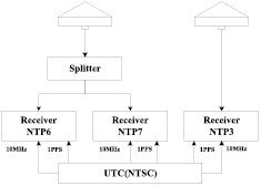
Figure 1. The connection diagram of receivers in NTSC.
Download figure:
Standard image High-resolution image3. Principle of GNSS CV time transfer
For GNSS time and frequency transfer, the local time and frequency reference signals are measured against the GNSS timing signals transmitted by the GNSS satellites. In CV, two or more remote timing laboratories make the CV measurements (the time differences between the local reference signals and the GNSS time from the same satellite at the same time). By differencing the CV measurements from two remote timing laboratories, the GNSS time in the CV measurements from the same satellite measured at the same time drops out and we obtain the difference of the two remote local reference clocks from the CV difference. The principle of GNSS CV is shown in the figure 2 and equations (1)–(3).
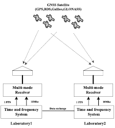
Figure 2. The GNSS CV principle.
Download figure:
Standard image High-resolution imageThe performance of GNSS CV is a function of the baseline between the two remote timing laboratories and is a function of the number of CV satellite used in the comparisons. For a short baseline, there are many satellites in CV by the two remote timing laboratories and the laboratories can make measurements to the same set of satellites in most time. By averaging the differences from the measurements to all CV satellites, the time transfer noise is greatly reduced. On the other hand, for a very long baseline, the two remote timing laboratories have hardly any CV satellite.
The time difference  between two laboratories can be described as follow:


 is time difference between lab j and satellite i,
  and
and  is time of lab j and satellite i separately.
  is the weight of combination of CV results between two laboratories from each satellite.
4. The clock solution for BeiDou with the Rinex2CGGTTS tools
In 1993, the Group on GPS Time Transfer Standard (GGTTS) of the Consultative Committee for the Definition of the Second (CCDS, now CCTF) developed a Technical Directive, GGTTS Version 01, for standardization of CV measurements processing and reporting. Only five years later, in 1998, the guidelines were updated to the Common GPS GLONASS Time Transfer Standard (CGGTTS, Version 02) for both GPS and GLONASS. With the development of BeiDou and Galileo, the Common GNSS Generic Time Transfer Standard, Version 2E (CGGTTS V2E) was published by the CCTF Working Group on GNSS Time Transfer (WGGNSS) in 2015. The CGGTTS V2E extends to CV measurements of Galileo, BeiDou and QZSS in addition to GPS and GLONASS. It is fully compatible with Version 01 and Version 02 [18]. ORB developed software, R2CGGTTS, for generating the CGGTTS format data of the GPS, GLONASS and Galileo measurements in the Receiver Independent Exchange (Rinex) format. The software is available on the BIPM FTP server.
Following the guidelines of CGGTTS Version 2E, NTSC developed the Rinex2CGGTS software for generation of BeiDou CGGTTS file. The BeiDou constellation includes GEO, IGSO and MEO satellites. The computation methods for obtaining timing information from GEO and from non-GEO are different. As the orbital inclination of the GEO satellite is close to 0, the coordinate rotation method is used in BeiDou GEO broadcasting navigation message. It needs to treat respectively for GEO and non-GEO satellite when we compute the satellite position. BeiDou transmits the signals by B1 (1561.098 MHz), B2 (1207.140 MHz) and B3 (1268.520 MHz) now. B1I and B2I are open service signals broadcasted by BDS-2. There are two timing group delay (TGD) parameters in the BeiDou navigation messages. The BeiDou TGD is referenced to B3 [19], i.e. TGD1 is the hardware code delay between B1–B3 and TGD2 is the hardware code delay between B2–B3. So the TGD correction should be determined for the B1 and B2 combination. The process of correction used for BeiDou CGGTTS data is presented below.
The ionospheric delay of the BeiDou measurements is corrected by the linear combination of the B1 and B2 dual-frequency code measurements (C2I, C7I in Rinex file), we denoted L3B here. Since both TGD1 and TGD2 are associated with B3, the TGD must be computed for L3B code hardware correction. The satellite clock bias of B1I and B2I correction with TGD parameters is described accurately in the interface control document (ICD) of BeiDou which is published in 2013 [20]. According to pseudorange observation equation,
Where  is the code measurements,
  is the true range to the satellite,
  denotes the light speed,
  denotes receiver clock bias,
  denotes satellite clock bias.
  is the tropospheric delay.
  is ionospheric delay of corresponding frequency.
The L3B observation equation can be written:
Where  and
and  denote the signal frequency of B1 and B2,
  and
and  are code measurements corresponding frequency.
Combining equations (4) and (5),
 is the satellite clock bias for B1.
  is the satellite clock bias for B2.
  is the residual error (such as troposphere delay between different frequencies
  , higher-order effects of ionospheric refraction and etc).
According to the BeiDou ICD, the satellite clock bias computation for each single-frequency user at B1 and B2 is:
 is the satellite clock bias, and
  and
and  are the TGD for each frequency which are broadcasted in the navigation messages.
The TGD correction for L3B code measurements can be written:
Using the sbf2cggtts software provided by the manufacturer of Septentrios receivers and the Rinex2CGGTTS software developed by NTSC, we compare the BeiDou CGGTTS results with them. The measurements on MJD 57963 were produced by the NTP6 receiver operated at NTSC.
Figures 3 and 4 are the time difference between UTC (NTSC) and BDT obtained from different satellites. Cxx is the pseudo-random noise (PRN) code number of BeiDou satellites (C1–C5 are GEO satellites, C6–C10 are IGSO satellites, C11–C14 are MEO satellites). The differences show that the results provided by receiver solution (with sbf2cggtts version 1.0.5) contain obvious biases between for measurements to different BeiDou satellites. (However, we would like to point out that the bias issue has been remedied in the new version 1.2.0 × by the receiver manufacturer).
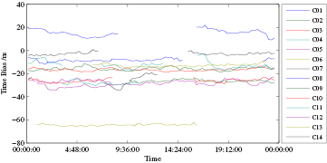
Figure 3. UTC (NTSC)-BDT from receiver solution (with sbf2cggtts version 1.0.5) for each satellite without calibration.
Download figure:
Standard image High-resolution image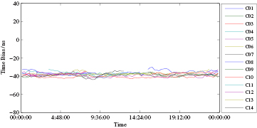
Figure 4. UTC (NTSC)-BDT from Rinex2CGGTTS solution for each satellite without calibration.
Download figure:
Standard image High-resolution imageTo evaluate the difference of two software, figure 5 shows the CCD between the NTP3 and the NTP6 receivers both were operated at NTSC. As the common error sources are canceled out, the STD of two CCDs are in the same level.

Figure 5. The CCD by different clock solution method (the top plot is the Rinex2CGGTTS solution, the bottom plot is the receiver solution).
Download figure:
Standard image High-resolution imageIn figure 6, the STD of UTC (NTSC)—BDT are also calculated for the time differences from different satellites at each epoch from MJD 57870 to MJD 57965. It shows the mean of the STD of the sbf2cggtts solution is more than 10 ns, which is agreed with figure 3. As the CCD between two software solutions is very close in figure 5, the bias of each satellite for the sbf2cggtts solution is most probably due to the TGD correction in the data processing. There is a step in top plot of figure 6; we do not know what happened at that time exactly, may be some changes have occurred in the navigation message. It should be studied in further. We will use the BeiDou CV data generated by the Rinex2CGGTTS software for the rest analyses.
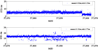
Figure 6. The STD of different satellite clock solution for Rinex2CGGTTS and sbf2cggtts (the top plot is the Rinex2CGGTTS solution, the bottom plot is the receiver solution).
Download figure:
Standard image High-resolution image5. Analysis of BeiDou CV time transfer
The evaluation of B1 and B2 code pseudorange measurements was completed before the experiment of BeiDou CV. All GNSS CV links which are used in the analysis are aligned to the corresponding GPS PPP links. The BeiDou CV time comparison experiment is implemented between three European UTC (k) laboratories and NTSC. And their results were compared with that obtained by the GPS, GLONASS and Galileo CV.
5.1. Evaluation of code pseudorange measurements
To assess the performance of BeiDou time transfer, we first analyzed the noise of the code observation. The two methods described in this section are used.
5.1.1. Assessment of the code measurements by the code multipath computation.
GNSS signals from satellites to receiver are affected by environmental interference. It reduces the precision of time comparison. The delays caused by troposphere, ionosphere and relativistic can be corrected by the experimental and mathematical models or other methods. But the multipath in receiving GNSS signal is specific to each receiver location for receiving the signals from a specific satellite and is one of the most difficult sources to predict and deal with. It cannot be corrected easily. Modern receivers minimize impact of multipath by the concept of 'narrow correlator'. Even that, the code multipath is also an important indicator to evaluate the quality of observations. Related research shows that the certain characteristics of GNSS code observations can be analyzed in a special linear combination of single-frequency code and dual-frequency phase observations which usually is called multipath (MP) observable. MP variations mainly show the tracking noise of the code measurements [21].
The code and carrier-phase measurements are given by:
Where  and
and  denote code and carrier phase pseudorange observation for ionosphere-free combination.
  denotes the geometric distance between phase center of the satellite and receiver antenna,
  and
and  denote receiver clock bias and satellite clock bias respectively.
  is the tropospheric delay,
  denote the multipath for code and phase.
  is the wavelength, and
  is the observed satellite phase ambiguity.
The code multipath can be written to equation (10) for the ionosphere-free linear combination of the carrier-phase measurement [19, 21]:
 and
and  denote the code multipath of the code observation for B1 and B2 respectively.
The code multipath could reach to 0.5 chip width of the code, but it is no more than 1/4 wavelength in carrier-phase measurement. The latter is much better than the former. So, the carrier-phase measurement can be reference in code measurement for estimating the code multipath.
From figures 7–12, we can conclude that the code multipath of B1 code measurements is more significant than that of B2. Obviously, there is correlation between the code multipath and the satellite elevation, especially for MEO satellites (C12 in figures 8, 10 and 12). Some papers also have found this phenomenon and which is defined as the satellite-induced code pseudorange variations [21].
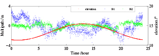
Figure 7. The code multipath of BDS C05 observed at SP.
Download figure:
Standard image High-resolution image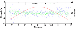
Figure 8. The code multipath of BDS C12 observed at SP.
Download figure:
Standard image High-resolution image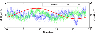
Figure 9. The code multipath of BDS C05 observed at PTB.
Download figure:
Standard image High-resolution image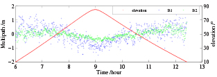
Figure 10. The code multipath of BDS C12 observed at PTB.
Download figure:
Standard image High-resolution image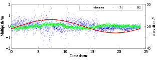
Figure 11. The code multipath of BDS C03 observed at NTSC.
Download figure:
Standard image High-resolution image
Figure 12. The code multipath of BDS C12 observed at NTSC.
Download figure:
Standard image High-resolution imageThe figures 13 and 14 present the relationship between the clock bias and the elevation of BeiDou satellite. The noise of clock bias is related to the elevation, which is indeed affected by satellite-induced code pseudorange variations. To solve this problem, the signal structure and the code measurement methods should be studied in advance.
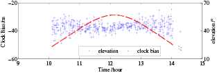
Figure 13. The relationship between the clock bias and elevation of BDS C12 observed by NTP6 at NTSC (MJD = 57963).
Download figure:
Standard image High-resolution image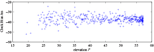
Figure 14. Clock bias plotted for C12 as a function of the satellite elevation observed by NTP6 at NTSC (MJD = 57963).
Download figure:
Standard image High-resolution image5.1.2. Assessment of the code measurements by the CCD.
Because co-located receivers using the same reference signals from a local clock and their antennas are placed very close to each other, the measurements of each co-located receiver contain the same amount of noise in receiving satellites signals. In the CCD of the CV measurements, the GNSS time as broadcasted by each satellite, the reference signals, and the noise introduced by the propagation paths are canceled. CCD represents the relative instability of two co-located receivers' measurements for a specific GNSS time and frequency transfer. The GNSS CCDs which are obtained by NTP3 and NTP6 receivers operated at NTSC are shown in figures 15–18. Hereafter GLO stands for GLONASS and GAL stands for Galileo.

Figure 15. The CCD of the BDS CV in NTSC.
Download figure:
Standard image High-resolution image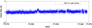
Figure 16. The CCD of the GPS CV in NTSC.
Download figure:
Standard image High-resolution image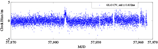
Figure 17. The CCD of the GLONASS CV in NTSC.
Download figure:
Standard image High-resolution image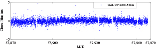
Figure 18. The CCD of the Galileo CV in NTSC.
Download figure:
Standard image High-resolution imageFrom figures 15–18, we can see that the noise of GPS, BDS, GLONASS and Galileo are almost in the same level. Table 2 shows the STD of the CCD between NTP6 and NTP7 receivers with common antenna and between NTP3 and NTP6 receivers with different antennas in NTSC.
Table 2. The different STD of CCD.
| GNSS system | STD of CCD (ns) (common antenna) | STD of CCD (ns) (respective antenna) |
|---|---|---|
| GPS CV | 0.38 | 0.46 |
| BDS CV | 0.57 | 0.77 |
| GLN CV | 0.56 | 0.83 |
| GAL CV | 0.38 | 0.55 |
5.2. Links calibration
The accurate time comparison requires the measurement of all the hardware delays from the antenna phase center to the local time reference point in both remote sites. This is known as time link calibration. It is not easy to obtain the absolute calibration in our experiment. Fortunately, the laboratories involved in the experiment are UTC(k) laboratories and their GPS time links have been calibrated by the BIPM [22]. Therefore, the relative calibration is chosen and all the GNSS CV links are aligned to their GPS time links respectively. Generally, The total delay (include reference delay, cable delay and internal delay) of the receiver in each link needs to be calibrated respectively. In our experiment, the sum of the total delay in two respective receivers is involved in each link for BDS/GAL/GLO CV. The sum of total delay for BDS/GAL/GLO CV links is shown in table 3.
Table 3. Sum of total delay of GNSS time transfer links.
| Labs | GNSS link | Total delay(ns) |
|---|---|---|
| SP-NTSC | BDS CV | 301.7 |
| GAL CV | 314.0 | |
| GLO CV | 293.3 | |
| ORB-NTSC | BDS CV | 247.4 |
| GAL CV | 242.1 | |
| GLO CV | 249.6 | |
| ROA-NTSC | BDS CV | 38.8 |
| GAL CV | 38.0 | |
| GLO CV | 43.0 | |
5.3. The BeiDou CV time comparison between NTSC and European UTC(k) laboratories
The BeiDou CV time and frequency transfer for the Chinese domestic and continental short baseline have been analyzed in recent years [5, 15]. In order to study the BeiDou long baseline CV time transfer, the ORB-NTSC, ROA-NTSC and SP-NTSC links using the BeiDou MEO satellites were established in first half of 2017. Table 4 shows some details about three BeiDou CV links. The data used in the study is from MJD 57870 to MJD 57965 and number is the total number of CV observation epochs.
Table 4. Information of the BeiDou CV time comparison links.
| Time link | Distance (km) | Code | Period | Number |
|---|---|---|---|---|
| ORB-NTSC | 8051 | L3B (B1&B2) | 57870–57965 | 8245 |
| ROA-NTSC | 9696 | L3B (B1&B2) | 57870–57965 | 7969 |
| SP-NTSC | 7193 | L3B (B1&B2) | 57870–57965 | 8505 |
The time comparison results for BeiDou, GPS, GLONASS and Galileo links over the three baselines are shown in figures 19–21 (In order to be easy to distinguish, the constants are added to the original value). Figures 22–24 illustrates the corresponding modified Allan deviation (MDEV) and time deviation (TDEV).
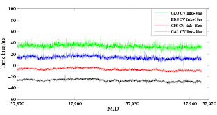
Figure 19. Time link results of UTC(ORB)-UTC(NTSC) with constants of +30 ns, +10 ns, −10 ns and −30 ns are added to improve the visibility for GLO CV, BDS CV, GPS CV and GAL CV respectively.
Download figure:
Standard image High-resolution image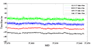
Figure 20. Time link results of UTC(SP)-UTC(NTSC) with constants of +30 ns, +10 ns, −10 ns and −30 ns are added to improve the visibility for GLO CV, BDS CV, GPS CV and GAL CV respectively.
Download figure:
Standard image High-resolution image
Figure 21. Time link results of UTC(ROA)-UTC(NTSC) with constants of +30 ns, +10 ns, −10 ns and −30 ns are added to improve the visibility for GLO CV, BDS CV, GPS CV and GAL CV respectively.
Download figure:
Standard image High-resolution image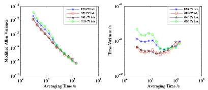
Figure 22. The MDEV and TDEV for different links between UTC(ORB) and UTC(NTSC).
Download figure:
Standard image High-resolution image
Figure 23. The MDEV and TDEV for different links between UTC(SP) and UTC(NTSC).
Download figure:
Standard image High-resolution image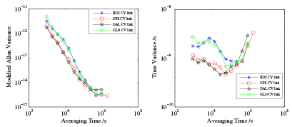
Figure 24. The MDEV and TDEV for different links between UTC(ROA) and UTC(NTSC).
Download figure:
Standard image High-resolution imageAll the time comparison links are double-differences with GPS PPP as common reference, and the standard deviation of the differences between CV results and the GPS PPP results are shown in table 5 for 95 d (from MJD 57870 to MJD 57965). The CV results are calculated with all CV satellites averaging with equal weight for each GNSS system, and the GPS PPP results (300 s interval) are linear interpolated into 16 min interval with the same time as CV epoch.
Table 5. The standard deviation of Europe-Asia GNSS CV links.
| Labs | GNSS link | STD(ns) |
|---|---|---|
| SP-NTSC | BDS CV | 2.90 |
| GPS CV | 1.24 | |
| GAL CV | 1.22 | |
| GLO CV | 3.11 | |
| ORB-NTSC | BDS CV | 2.03 |
| GPS CV | 1.13 | |
| GAL CV | 1.15 | |
| GLO CV | 3.01 | |
| ROA-NTSC | BDS CV | 4.06 |
| GPS CV | 1.84 | |
| GAL CV | 1.58 | |
| GLO CV | 3.98 | |
Figure 25 presents the number of the BeiDou CV satellites for the three Europe-Asia links. From table 5 and figure 25, we can conclude that the STD of BeiDou CV links will be less than 3 ns and even can arrive to 2 ns when the signal coverage is under the good conditions, e.g. ORB-NTSC and SP-NTSC link can view more than two satellites in most time. Figure 26 also provides the valid observation points of four UTC (k) laboratories in different elevation for BDS. Obviously, the coverage of BeiDou is better in Asia-Pacific than Europe for BDS-2. We can expect the performance of BeiDou CV will be greatly improved after the BeiDou system completes the global coverage in BDS-3.

Figure 25. Distribution of CV satellite of GPS, GLONASS, Galileo and BeiDou between European laboratories and NTSC.
Download figure:
Standard image High-resolution image
Figure 26. The valid observation points in laboratories at different elevation for BDS.
Download figure:
Standard image High-resolution image
6. Conclusion
In this paper, we presented a quick review of the BeiDou system and the GNSS time transfer techniques. The setups of multi-GNSS receivers and three Europe-Asia UTC (k) baselines used in this study were introduced. Then, we briefly recalled the principal of the GNSS CV method for the remote clocks comparison. We have shown the Rinex2CGGTTS software developed by NTSC for the realization of BeiDou CV correctly applied the TGD in generating the CGGTTS BeiDou CV measurements. It has been used in our study of the Europe-Asia time comparisons. The performance of the BeiDou code measurements was evaluated by code multipath and CCD methods. Finally, the performances of BeiDou and other three GNSS CVs were compared to each other. All of these GNSS links are aligned to the GPS time links. It is shown that the STD of BeiDou CV links is less than 3 ns and can reach to 2 ns when the signal coverage is in the good conditions. The STD of BeiDou CV is a little lower than or at about the same level compared to that of GPS, GLONASS and Galileo now. The main cause of this is the BeiDou MEO satellite coverage. Even this is the second phase of BeiDou, the experimental result of three months is continuous, stable and smooth. With the development of BeiDou system, it will provide the global open service. The better performance of BeiDou time comparison could be expected and we also look forward that it could contribute to the generation of UTC/TAI in next few years.
Acknowledgment
The authors thank ORB, RISE or SP, PTB and ROA for their data sharing and technical assistance. Thank BIPM and ORB for sharing CGGTTS software. And also thank the National Natural Science Foundation of China (Grant No. 11703030, No. 11773030) and National Key R&D Program of China (Grant No. 2016YFF0200203) for their funds support.