
Abstract
Using the China Spallation Neutron Source (CSNS) linac as the injector, a 500 MeV proton synchrotron is proposed for multidisciplinary applications, such as biology, material science and proton therapy. The synchrotron will deliver proton beam with energy from 80 MeV to 500 MeV. A compact lattice design has been worked out, and all the important beam dynamics issues have been investigated. The 80 MeV H− beam is stripped and injected into the synchrotron by using multi-turn injection. In order to continuously extraction the proton with small beam loss, an achromatic structure is proposed and a slow extraction method with RF knock-out is adopted and optimized.
Export citation and abstract BibTeX RIS
1. Introduction
Particle beams have been used for studies of molecular biology, the single particle effect in electric components, and cancer therapy in recent years, because of their large relative biological effectiveness and small beam diffraction [1]. Many proton synchrotron complexes have been or are being constructed around the world [1–7]. Using the China Spallation Neutron Source (CSNS) [8] linac as the injector, a 500 MeV proton synchrotron is proposed for multidisciplinary applications. It will deliver proton beam with energy from 80 MeV to 500 MeV. The CSNS linac provides 80 MeV H− beam for injecting into a Rapid Cycling Synchrotron (RCS) with a repetition rate of 25 Hz and a duty factor of 1.25%. The linac can provide an additional beam pulse in the time between two RCS injections, so it can be an injector for another synchrotron.
A typical design for a proton synchrotron complex is to provide the proton beam with smooth spill, reliability and simplicity of operation. For low cost, the vertical betatron function should be small to decrease the aperture of the dipole magnet. To reduce the space charge effect and accumulate higher intensity beam, multi-turn injection is always used. The extraction is a key point. The quality of the extraction beam spill depends on stable extraction from the synchrotron over the period of extraction. To share the linac beam with the RCS, a transport line from the CSNS linac to the 500 MeV synchrotron was designed. A compact 500 MeV synchrotron was worked out with optimized injection and extraction design, and related beam dynamics studies were also done.
2. Design of transport line from linac to 500 MeV synchrotron
The CSNS LRBT (Linac to RCS Beam Transport) consists of a straight section and a bending section connected with a switch dipole (SWITCH). The beam dump line (dump line) and two beam dumps (dump 1 and dump 2) are designed for beam commissioning. The H− beam is bent to the RCS or to two beam dumps controlled by the SWITCH as shown in Fig. 1 [8]. The linac beam is bent to the RCS when SWITCH is switched on with positive magnetic field, the beam delivers to dump 1 when SWITCH is off and it enters beam dump line and dump 2 when SWITCH is switched on with negative field and the dipole (LDSW) in the beam dump line is switched on. A port has been reserved for sharing the linac beam in the beam dump line when LDSW is switched off. To share the beam to the reserved port and keep the dump line unchanged, the H− beam is stripped to protons upstream of the SWITCH. As shown in Fig. 1, a bump is generated by three pulse dipole magnets, and the short beam pulse for the 500 MeV synchrotron is guided to the stripping foil and stripped. The proton beam will be automatically guided to the reserved port when LDSW is switched off.
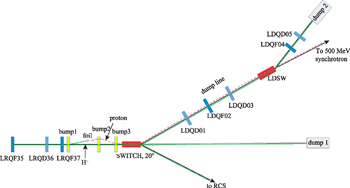
Fig. 1. Layout of the transport line from the linac to the 500 MeV synchrotron. The solid lines are the transport lines of the H− beam and the dashed line is the proton beam transport line.
Download figure:
Standard image High-resolution image3. Lattice design of the synchrotron
A compact 500 MeV synchrotron is designed and its layout is shown in Fig. 2. The lattice of the synchrotron adopts the FODO cell based 2-fold structure, which consists of 8 dipoles and 12 quadrupoles powered by 4 families of power supply. The ring is made up of two arc sections with reasonable dispersion function and two achromatic straight sections of 4 m respectively, which are reserved for the accommodation of the elements of injection, extraction, RF cavities and resonance sextupoles. The linac beam is injected into the ring by an injection magnetic septum (IMS) and an electrostatic inflector (IEI). Two bump magnets are located at the two sides of the injection section with phase advance of 180° for depressing closed orbit distortion (COD) in the injection period. Accelerated beam is successively extracted by an extraction electrostatic septum (EES) and a magnetic septum (EMS). As a compact synchrotron, regular dipole magnets with 1.8 m length and 1.6 T are used, and the good field region of the dipole is about 120 mm with a gap of 60 mm. The aperture of the quadrupoles is generally 120 mm, but some of them, in the injection and extraction sections, are bigger than 120 mm. Short drifts in the arc are reserved for chromatic sextupoles and RF knock-out (RFKO).
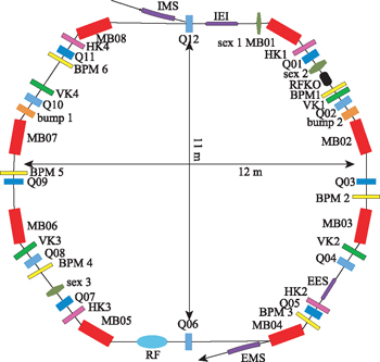
Fig. 2. Layout of the 500 MeV synchrotron.
Download figure:
Standard image High-resolution imageThe parameters of the synchrotron are listed in Table 1. The horizontal acceptance of the ring is 200 π·mm·mrad. Injection energy is designed to be 80 MeV. Figure 3 shows the Twiss parameters of the synchrotron. The advantage of this design is as follows: (1) it is a compact structure; (2) the horizontal and vertical betatron functions are limited to be 9 m; (3) it has larger dispersion area along with smaller beta function; (4) there are two achromatic straight sections for robust injection and extraction. The COD is mainly from the field errors and misalignment of dipoles and quadrupoles. In order to correct COD, 6 horizontal BPMs, 6 vertical BPMs, 4 vertical steering magnets and 4 horizontal steering magnets are considered to meet the goal of 1 mm corrected COD.
Table 1. The main parameters of the synchrotron.
| parameters | units | values |
|---|---|---|
| circumference | m | 40 |
| inj. energy | MeV | 80 |
| ext. energy | MeV | 500 |
| maximum βx/βy(H/V) | m | 9.2/8.9 |
| transition γ | 1.89 | |
| nominal tunes (H/V) | 1.71/1.24 | |
| natural chromaticity (H/V) | −0.47/−1.74 | |
| repetition rate | Hz | 0.5 |
| acceptance (H/V) | π ·mm·mrad | 200/50 |
| momentum deviation | % | 0.3 |
| accumulated proton number | 5×10¹¹ | |
| injection pulse current | mA | 15 |
| extraction average current | nA | 40 |
| harmonic number | 1 | |
| RF frequency | MHz | 2.8−5.8 |
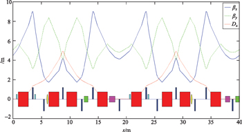
Fig. 3. Twiss parameters of the synchrotron.
Download figure:
Standard image High-resolution image4. Injection design and simulation
The 80 MeV proton beam from the CSNS linac is injected into the synchrotron by using multi-turn injection in the horizontal plane. The injection system consists of IMS, IEI and two bump magnets (bump 1, bump 2) with phase advance of 180°. The number of turns for each injection period is about 10, and the number of injected particles per turn is more than 8×10¹⁰ for the typical injector beam. For proton beam with energy of 80 MeV, when the space charge limited intensity is limited to 5×10¹¹ ppp, the space charge tune shift is much smaller than 0.1. Injection beam is painted by sweeping the bump height.
A code for injection tracking of the synchrotron was developed based on AT [10, 11] and the beam injection was studied by the code. A linac beam of 1000 macro-particles per turn was injected in the tracking, a constant ramping rate of the bump field was assumed, and the thickness of the IEI was set to 0.2 mm. The beam distribution in horizontal phase space after painting is shown on the left-hand side of Fig. 4. The green line is the location of the IEI, the red dot on the right denotes the injection beam and the blue dots on the left side of the line are the accumulated cycling beam. The injection beam is painted at about 60 π·mm·mrad in the horizontal plane. The survival rate of the injection beam after 40 turns is displayed in the right-hand plot of Fig. 4. The efficiency of injection without space charge effect is about 60% and the bean loss at the IEI is about 20%.
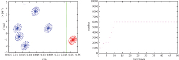
Fig. 4. The beam distribution at injection point (left) and accumulated rate (right).
Download figure:
Standard image High-resolution image5. Extraction design and simulation
The 3rd resonance slow extraction with RF knock-out scheme is used to obtain continuous and smooth spill. The layout is shown in Fig. 2. Two resonance sextupoles (sex 1 and sex 3), RFKO, EES and EMS were used. Resonance sextupoles are placed in two dispersion-free regions. The phase advance between the main resonance sextupole (sex 1) and EES is well above the permissible minimum of 217° and close to the ideal value of 225°. The phase advance from EES to EMS is 39°, which can provide 62 % of the kick of 90° phase advance. The RFKO is located in the arc. The dispersion function is correctly configured with Dx > 0 and  at EES to meet the Hardt condition [12]. At the resonance sextupole, βx ≈ βy induces the largest coupling, but this is not a problem for beam stability in the vertical plane. βx is large to enhance the kick at EES and βy is small to reduce the aperture requirement of EMS.
The accelerated beam is extracted by the slow extraction scheme using a third order resonance υx = 5/3 with transverse RFKO. The tune in the horizontal plane is adjusted from 1.71 to 1.67 before beam extraction. The phase space is shaped into a triangle when resonance sextupoles operate. Particles inside the triangle are stable while particles out of the triangle are unstable and will be extracted quickly. The stability of extracted beam parameters, for example beam position, beam size and momentum deviation, are very important issues for special experiments, such as spot scanning irradiation and single particle effect studies. In the RFKO method, the separatrix is kept constant during the whole extraction period, so it is easy to control the extraction by using RFKO.
The simulation code based on AT [11] has also been developed in order to analyze a mechanism of realistic RFKO and to realize more precise control. The maximum spiral step is bigger than 4.5 mm. There is a few percent beam loss at the EES and the extraction efficiency is over 95 % in the tracking. The two extraction schemes, the scheme with sextupoles only and the scheme with sextupoles and RFKO, are compared. Figure 5 shows the extraction beams versus extraction turn. The left-hand plot is the extraction with only resonance sextupoles. The particles are extracted over several hundred turns. A lot of particles inside the stable triangle are difficult to extract. The particles can be continuously extracted by combining the sextupole and RFKO, as shown in the right plot, and the spill is smoother.
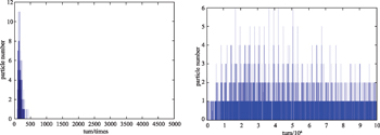
Fig. 5. Number of extracted particles per turn by using only the resonance sextupole (left) and the sextupole with RFKO (right).
Download figure:
Standard image High-resolution imageThe ripple of the dipole and quadrupole power supplies induces fluctuation of tune, which changes the stable triangle, thus the number of extraction particles varies with the ripple of the power supply. This is awful for spot scanning, so the ripple should be well controlled. The ripple effects were studied by simulation with different ripple levels. For a few percent of extraction variation, the ripples of dipoles and quadrupoles are 5 ppm and 20 ppm, respectively.
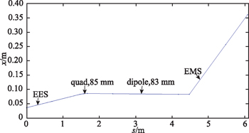
The orbit of the extraction beam as it passes through the EES and EMS is shown in Fig. 6. To reduce the beam loss in extraction, the apertures of the dipole and two quadrupoles are bigger than other general magnets in the ring. The electric field of the EES and magnetic field of the EMS are 6.1 kV/mm and 0.98 T respectively.
Fig. 6. Orbit of the extraction beam. The value is the half aperture of the magnets.
Download figure:
Standard image High-resolution image
6. Summary
Using the China Spallation Neutron Source (CSNS) linac as the injector, a 500 MeV proton synchrotron is proposed for multidisciplinary applications. The compact synchrotron with two achromatic straight sections is useful for robust injection and extraction. An acceleration-driven resonant extraction scheme using RFKO is chosen to offer the smoothest spill of the particles for particular experiments. Based on AT, a simulation code of injection and extraction was developed. The particle tracking simulation for injection confirms the required conditions of bump magnets, IMS and IEI. The particle tracking simulation for extraction shows that the beam can be extracted with high efficiency. The influence of ripple of magnets and the orbit of extracted beam are optimized for smooth spill.
We would like to acknowledge the support of many colleagues, especially Prof. N Huang for many discussions and comments on this study