


Abstract
We report a compact and robust micro air cavity (MAC) incorporated tip tapered photonic crystal fiber (PCF) based interferometer point probe for refractive index (RI) sensing. Two sections of PCF are spliced and tapered and the tapered collapsed section is cleaved to form a tip tapered PCF. One end of the PCF is spliced with a single mode fiber while the tapered tip of PCF is subjected to laser micromachining which results in the formation of a micro-groove at the tip. The laser micromachining enables the formation of micro-groove even on a roughly cleaved tapered section. The micro-groove is post processed using a fusion splicer in order to form a MAC at the tip which appears like a 'ball-pen'. The presence of MAC helps in the formation of sharp interference pattern that can be used for precise monitoring of RI. Using this procedure, three probes are fabricated with varying parameters. The maximum RI sensitivity is found to be 158.41 nm RIU−1 with resolution being 6.31 × 10⁻⁵ RIU. Further, the sensitivity of the probe to variation in environmental temperature is found to be 29.14 pm/ C.
C.
Export citation and abstract BibTeX RIS
1. Introduction
Optical fiber based interferometers have been widely used for numerous sensing applications owing to their unique properties such as portability, immunity to electromagnetic interference, remote-sensing capability, and appreciably high sensitivity [1–4]. Among these applications, detection of refractive index (RI) plays an important role due to its requirement in chemical, biological and environmental fields. Several types of fiber based interferometric RI sensors have been developed for operation in both transmission and reflection mode. In this context, the reflection based interferometers are comparatively more compact due to the fact that the same fiber is used for delivering as well as collection of light and therefore, they are the most suitable candidates to be used as a point probe which is a crucial and important requirement from commercial view point. Further, reflection-based fiber interferometric schemes could be deployed as tip based RI sensor where the tip could be inserted into a region containing nominal amount of liquid. Considering such advantageous features, several variants of reflective fiber-optic probe have been employed in a wide-range of RI sensing applications [1–3]. In addition, several approaches have been made in order to improve the compactness, response and strength of evanescent field in reflection based sensing probes. For example, a tapered single mode fiber (SMF) based interferometer has been found to have a sensitivity of −49.96 nm RIU−1 [5]. Further, chemically etched tapered fiber, microfiber based half coupler, s-tapered fiber have also been developed for RI sensing [6–9]. In the last few decades, photonic crystal fiber (PCF) for their specific properties such as low temperature sensitivity and tunable geometrical property have shown promise for RI sensing applications [10–13]. For example, a concave core PCF has been utilized for a Fabry–Perot based interferometric RI sensor [14]. The PCF based interferometers for RI sensing are primarily based on transmission based measurement due to its simplicity in experimental design. Although, there are a few reports on reflection based PCF interferometric configurations, they suffer from complex design and implementation scheme. For example, a PCF with spherical end facet has been utilized for RI sensing in reflection mode. In this case, the length of collapsed region has been optimized which results in the period of interference pattern to be approximately 20 nm. However, the fabrication of a spherical faceted tip is reasonably difficult to realize [15]. Further, cleaved PCF based interferometer have been utilized for dew detection in reflection mode. Such configurations suffer from limited utility in a liquid environment where the holes of PCF could be filled with liquid and subsequent utility of the probe in another liquid environment is discernibly challenging [16]. Moreover, a PCF half-taper based probe has been utilized for RI sensing where PCF of length 40 mm has been tapered and cleaved using CO2 laser and the tip has been coated with gold [17]. However, the probe fabrication is quite complex and exhibits low RI sensitivity. In addition, small diameter (3.2 µm) of the tapered section, renders the probe more fragile. The mechanical strength of the device further reduces due to the collapse of the middle-part of the PCF which senses the change in RI [18]. In another configuration, PCF has been coated with palladium film for detection of hydrogen [19]. An interesting interferometric configuration was devised utilizing a special type of PCF for realizing a tip based sensor [20]. In this case, the PCF has been spliced with SMF to form an air cavity at the spliced region and a solid sphere at the tip of PCF has been fabricated by applying arc. It is worthwhile to note that the use of specialized PCF and relatively low probe sensitivity of 11.5 nm RIU−1 are a few of the disadvantages of the probe.
Here, we report a compact tip-tapered PCF incorporated with a micro-air channel (MAC) as a point-probe for RI sensing of analytes. PCF tapering has been accomplished using a commercial fusion splicer while the MAC is fabricated using laser micromachining followed by arc technique. The presence of MAC helps in improved light reflectance as well as obtaining better resolved interference pattern which in turn improves the precision of measurement. Additionally, the probe could be immersed in analyte and the interference pattern could be analyzed remotely using optical spectrum analyzer.
2. Fabrication of the probe
The fabrication of the probe is accomplished using a commercial fusion splicer (Fujikura 80 C+). First, a section of SMF is spliced with a section of PCF (LMA, NKT photonics, UK) resulting in the formation of collapsed region of approximate length 180 µm at the splicing junction of the two fibers as shown in figure 1(a). PCF is subsequently cleaved so that the length of PCF section after the collapsed region is approximately 3 mm as shown in figure 1(a). Following the same procedure, another section of SMF-PCF junction is prepared with length of PCF fixed at 3 mm. The PCF section of each of the components are kept in between two electrodes of a splicer and the parameters of the splicer are fixed in such a way that both these sections are spliced and tapered as shown in figures 1(b) and (c). In order to achieve this, the arc power and the arc time of the splicer are fixed at 'Std' and 3000 milliseconds respectively where Std refers to standard value. On the other hand, the parameters such as tapering speed and tapered diameter are fixed at 20 bit and 300 µm respectively. During splicing, the holes of the PCF completely collapse and subsequently, the collapsed region is tapered. This tapered section is carefully cleaved at the middle using a microscope so that a section of PCF with tapered (as well as collapsed) tip is formed as shown in figures 1(d) and (e) with waist diameter of 64 µm.
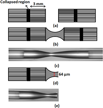
Figure 1. (a) shows the schematic of the collapsed region at SMF-PCF splicing junction along with the cleaved PCF. (b) and (c) show the schematic diagram and microscopic picture of the tapered-collapsed region formed at the junction of two PCF sections respectively. (d) and (e) show the schematic diagram and microscopic picture of the cleaved tapered section respectively.
Download figure:
Standard image High-resolution imageThe tapered collapsed tip is considered for laser micromachining for the fabrication of MAC. In order to accomplish this, optimally focused femtosecond pulses from an ultrashort-pulse laser (FLCPA-07U-30, CALMAR, USA) is incident on the tip of a tapered section using a microscope objective (MO) (20X) as shown in figure 2(a). The pulse repetition rate and pulse-width of the laser are fixed at 1 KHz and 320 femtosecond respectively which ensures an incident laser energy to be 30 microjoule. The tapered PCF is kept on a XYZ translational stage so that the tip of the tapered section is near the focus of MO. The beam from the laser is focused onto the center of the tapered tip of PCF. This results in the formation of a micro groove on the tip of tapered section whose schematic picture and microscopic image is shown in figures 2(b) and (c) respectively. The depth of the micro-groove is approximately 47.04 µm and width is 25.53 µm. The front section of the groove is wider than the inner one due to the Gaussian beam profile of the focused beam. The micro-groove incorporated tapered tip is now placed in between the two electrodes of the splicer and an arc of duration 1500 millisecond is used to seal the tip of micro-groove as well as trapping of air-bubbles to form a micro air-cavity (MAC) in a silica bulb as shown in figures 2(d) and (e) respectively. It could be observed in figure 2(e) that a very thin silica layer (approximately 2.6 µm) separates the MAC from the ambient medium. The other parameters of the resulting probe is shown in figure 2(e). It could be observed from the figure that the length of the tapered (and collapsed) region is 432 µm (approx.), the horizontal and vertical diameter of the MAC is 52 µm (±1 µm) and 60 µm (±1 µm) respectively.

Figure 2. (a) shows the experimental set up for the fabrication of micro-groove on tip of collapsed tapered PCF. (b) and (c) shows the schematic and microsopic picture of the micro groove on tip of the tapered PCF respectively. (d) and (e) show the schematic diagram and microscopic pictures of MAC incorporated tapered-tip respectively.
Download figure:
Standard image High-resolution imageFollowing the procedure described above, we fabricated three probes as shown in figure 3. The length of PCF is 3 mm, 6 mm, and 8.5 mm for probe-1, probe 2 and probe 3 respectively. Although the splicer parameters are same for each of the probe, the length of the tapered section in each of the probe varies depending upon the length of the cleaved position. The variation in cleaved position is due to the use of manual cleaver where there are errors in the order of hundreds of micrometers. As can be seen from figure 3, the length of the collapsed tapered section of PCF varies from 357 µm to 454 µm. Further, the position of tip of micromachined tapered section with respect to electrode also affects the position and size of MAC. Although, the size of MAC and length of tapered section are different for all the three probes, the sensitivity may not be affected much by these factors. This is due to the fact that the variation in size of MAC is in the order of few microns and that in case of length of tapered section is in order of few hundred micrometers. On the other hand, the variation in length of PCF is in the order of few millimeters which is one order higher than that of MAC and length of tapered section. Therefore, the effect of length of PCF on the RI sensitivity is analyzed.
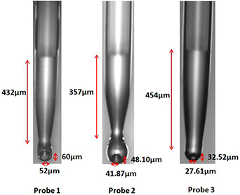
Figure 3. Microscopic pictures of all the three probes along with parameters.
Download figure:
Standard image High-resolution imageIt can be noted that there are several advantages of using PCF based tip-tapered probe over conventional SMF based tapered probe. The tapered PCF is composed of fused silica and it acts as a multimode fiber with air as cladding. Therefore, the evanescent tail of modes easily reach the surface of the tapered section. This, in turn, facilitates improved interaction of evanescent mode-field with the external environment (analyte). In case of tapered SMF (diameter ∼70 μm), the mode-field is strongly confined to the core (in the wavelengthregion of interest) and the extent of evanescent tail is minimal at the outer surface in comparison to that for a fused silica. In addition, the presence of holes in PCF helps in reducing the impact of temperature fluctuations on the probe performance. The presence of dopants in conventional SMF, on the other hand, enhances the temperature sensitivity.
It is worth noting that of the proposed probes (ball-point pen-shaped) are exceptionally compact and offer high mechanical stability due to very small length of the PCF as well as the MAC incorporated tapered-tip. This provides appreciably high mechanical stability to the configurations in comparison to long tapered lengths [17]. In conventional long tapered length probes, if the cleaved tapered tip remains rough or oblique, the resultant interference pattern (in reflection mode) would have weaker contrast between maxima and minima. This would unavoidably have an adverse effect on refractive index measurement and enhance the possibility of errors. On the other hand, the formation of micro-groove as well as MAC remains unaffected by the alignment of the cleaved surface in our case. Subsequently, the present scheme is highly tolerant to tip-roughness or improper cleaving. The presence of MAC enhances the mechanical stability of tip for tapered-collapsed region. This is due to the fact that the bulged silica section (surrounding the MAC) protects the tip from strong external perturbations. The degrees of freedom to modify the interference pattern is more in the probes presented here. For example, the number of interference minima in a given wavelength can be changed either by changing the length of PCF or the length of tapered section or the diameter of MAC [16]. By virtue of this, the probe sensitivity could be enhanced by increasing the PCF length without perturbing the tapered-section length or the MAC diameter. This is in contrast to the case in conventional SMF based tapered probes where the sensitvity enhancement could be brought about through increasing the tapered section lengthand this could unavoidably could render the probes to be fragile.
3. Experimental set up
The experimental set up for the detection of RI of analytes is shown in figure 4(a). As shown in figure, light from a Superluminiscent Light Emitting Diode (SLED) source is coupled to one arm of the circulator. Then the light passes through the second arm containing PCF and MAC and gets reflected from the MAC and the reflected light is coupled to the third arm of the circulator connected to optical spectrum analyzer (OSA). As the light propagates through the collapsed region, the fundamental mode expands spatially and subsequently, excites the core and cladding modes in PCF as shown in figure 4(b). These modes combine at the tapered collapsed region and get reflected from the two surfaces of MAC. The reflected light in turn passes through the tapered section followed by core and cladding of PCF. Finally, the light from core and cladding of PCF combine at the collapsed region and gets filtered through the SMF and ultimately coupled to OSA through the third arm of the circulator. It is to be noted here that, although the resultant interference pattern is due to the interference of core and cladding mode of PCF, the background contains the signature of the reflected light from the surface of MAC. This is primarily a consequence of the fact that the light reflected from the MAC surface cause partial excitation of core and cladding modes of PCF. The presence of MAC results enhances the sharpness of interference pattern as compared to a situation without absence of MAC which could be observed in figures 5(a) and (b).
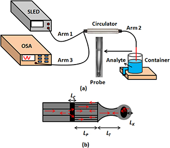
Figure 4. (a) shows the experimental set-up for the detection of change in RI of analyte and (b) shows a schematic of light propagation through the probe.
Download figure:
Standard image High-resolution image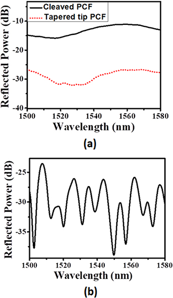
Figure 5. (a) shows the interference pattern corresponding to the probe with a cleaved PCF and tapered-tip PCF. (b) shows the interference pattern for a probe with MAC at the tapered PCF tip.
Download figure:
Standard image High-resolution imageIt could be seen observed from figure 5(a) that, within a given wavelength range, a broad interference minimum is formed corresponding to the probe with a cleaved PCF (without MAC) and a tapered tip PCF (also without MAC). On the other hand, the tapered tip PCF with a MAC produce discernible interference fringes within the same wavelength range as shown in figure 5(b). This enables the probe to be used for precise monitoring of shift of minima caused due to the external perturbation. The interference can be described by where I1 and I2 corresponds to the intensity of reflected light in the core and cladding of PCF respectively and I correspond to the total intensity of reflected light in the core of PCF. Δneff and L refer to the difference between effective indices of core and cladding modes and length of the probe respectively. The probe length consists of length of PCF (LP), length of tapered collapsed region (LT), diameter of MAC (d) and length of portion of silica present after MAC (LK) as shown in figure 4(b).
4. Results and discussions
In order to detect the variation in RI of analytes, the fabricated probe is kept in a container which has been filled with analyte through the inlet and evacuated through outlet duct. The interference pattern without the presence of analyte i.e. in presence of air is recorded. This is followed by recording the interference fringes when various analytes are separately filled within the container. After recording each measurement, the probe is dried so that the interference fringes coincide with the ones recorded using air as ambient medium. When the RI of analyte increases, the interference fringes (of same order) exhibit a red shift. The red shift of interference pattern for all the three probes is shown in figures 6(a)–(c). The shift of interference minima occurs due to the interaction of evanescent tail of the cladding mode with RI of analyte i.e. the effective index of cladding modes of PCF as well as the collapsed tapered section changes on interaction with analyte which in turn changes Δneff. The variation in shift of the interference minima with change in RI of analyte for all the three probes is plotted in figure 6(d). These variations are apparently linear and the R2 value of these linear plots can be seen in the inset of figure 6(d). The RI sensitivity of these probes can be calculated form the slope of linear plots and are found to be 64.0 nm RIU−1, 118.5 nm RIU−1 and 158.4 nm RIU−1 for probe 1, probe 2, and probe 3 respectively. These values are significant improvement in comparison to previously reported results [17, 20, 21]. Further, the variation in sensitivity for all the three probes having different value of LP is shown in figure 7 which shows linear behavior. This occurs due to the increase in optical length of the cladding mode thereby increasing the phase difference between core and cladding modes of PCF. This is a significant improvement in sensing using reflection based PCF interferometric configurations. In our case, the resolution of the sensor is being determined from the measured spectrum of the reflected light from the fiber. With OSA spectral resolution of 0.01 nm, the minimum refractive index change (or resolution) of the proposed sensor is estimated to be 6.31 × 10⁻⁵ RIU. This is a significant value for reflection based interferometers. In addition to variation in RI of analytes, the ambient temperature has a significant impact on the sensor performance.
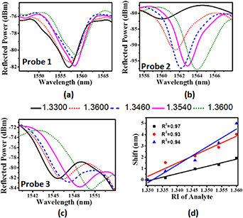
Figure 6. (a), (b) and (c) shows the shift of interference minimum for probe 1, probe 2 and probe 3 respectively. (d) shows the variation in shift of interference minimum with RI of analytes.
Download figure:
Standard image High-resolution image
Figure 7. Variation in RI sensitivity with length of PCF (LP). The value of LP for three probes are 3 mm, 6 mm and 8.5 mm respectively.
Download figure:
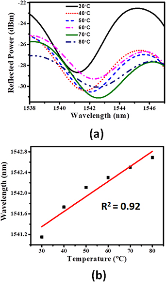
Standard image High-resolution imageThe effect of temperature on the resultant interference pattern of the probe 1 is studied by keeping the probe on a hot plate whose temperature could be controlled precisely. The temperature is gradually increased from room temperature to 100 °C. The plate is kept at each constant value of temperature for ten minutes and the corresponding interference traces are recorded. When the temperature is increased from 30 °C to 80 °C, the wavelength corresponding to the minima of interference pattern shifts from 1541.15 nm to 1542.69 nm which could be observed in figure 8(a). The variation in wavelength of minima of the interference fringes with change in temperature is shown in figure 8(b) which shows linear behavior with slope of the variation being 29.14 pm/˚C . Although, the holes in PCF as well as the MAC helps in lowering the temperature sensitivity, the higher value of temperature sensitivity can be attributed to the presence of tapered collapsed section of the PCF. This region acts as multimode fiber and the variation in effective index of cladding mode with increase in temperature is appreciably strong. The red shift of the interference fringes could be attributed to the thermal expansion in silica and its thermo-optic coefficient. The shift in minima of an interference fringe with variation in temperature could be expressed as [22],

where Lprobe = Lc + LP + LT + LK. Here Lc, LP, LT, and LK refer to length of the collapsed region of PCF, length of PCF, length of tapered collapsed section, and length of the portion of silica after the MAC respectively whereas 'n' defines the RI of silica. In this case we have neglected the thermo-optic coefficient of air. The parameters such as Lc, LP, LT, and LK increase with increase in temperature due to the positive thermal expansion coefficient of silica while dn/dT (thermo-optic coefficient) is positive for silica. This results in increase of Δλmin which corresponds to the red shift of the interference pattern.
Figure 8. (a) shows the shift in interference minimum with change in ambient temperature. (b) shows the variation of wavelength for an interference minimum for different ambient temperatures.
Download figure:
Standard image High-resolution image
5. Conclusion
A compact PCF based modal interferometer in reflection geometry has been reported. The interferometric configuration consists of a PCF having a MAC incorporated tapered tip on one end. The tapered PCF has been fabricated by splicing and tapering two-sections of PCF using a commercial splicer machine and the resulting tapered section is cleaved in the middle to form a tip tapered PCF. An optimally focused beam from an ultrashort pulsed laser has been focused on to the tip of tapered PCF resulting in the formation of a micro-groove and the microgroove facilitates in formation of MAC when it is subjected to a suitable arc. Three probes have been fabricated with each having different lengths of PCF. The formed 'ball-pen' shaped point probes has been dipped in analyte of varying RI and the maximum sensitivity has been found to be 158.41 nm RIU−1. Further, effect of change in environmental temperature on the probe has been studied where the temperature sensitivity has been found to be 29.14 pm/ C. Therefore, this compact and robust probe could be employed as a precise point refractometer in environmentally harsh conditions.
Acknowledgments
Jitendra Narayan Dash thanks the Science and Engineering Research Board (SERB), New Delhi, India, for the NPDF fellowship (File No. PDF/2017/001924).