

Abstract
Astronomical images often have regions with missing or unwanted information, such as bad pixels, bad columns, cosmic rays, masked objects, or residuals from imperfect model subtractions. In certain situations it can be essential, or preferable, to fill in these regions. Most existing methods use low order interpolations for this task. In this paper a method is described that uses the full information that is contained in the pixels just outside masked regions. These edge pixels are extrapolated inwards, using iterative median filtering. This leads to a smoothly varying spatial resolution within the filled-in regions, and ensures seamless transitions between masked pixels and good pixels. Gaps in continuous, narrow features can be reconstructed with high fidelity, even if they are large. The method is implemented in maskfill, an open-source MIT licensed Python package (https://github.com/dokkum/maskfill). Its performance is illustrated with several examples, and compared to several alternative interpolation schemes.
Export citation and abstract BibTeX RIS

Original content from this work may be used under the terms of the Creative Commons Attribution 3.0 licence. Any further distribution of this work must maintain attribution to the author(s) and the title of the work, journal citation and DOI.
1. Introduction
Image masking serves various purposes. Detector defects, such as hot pixels, bad pixels, or bad columns, result in predictable locations where data cannot be trusted or are missing altogether. Cosmic ray hits can occur anywhere on the detector, producing short trails of very bright pixels (Leach & Gursky 1979). Both detector defects and cosmic rays are routinely masked in the early stages of the data reduction process.
Another reason for masking is if certain objects are unwanted. An example is masking of bright stars and galaxies in data that are searched for low surface brightness emission (Greco et al. 2018; Montes & Trujillo 2018; Danieli & van Dokkum 2019). A variation on this theme is the masking of residuals after image subtraction. Image subtraction is routinely performed in transient photometry (Kessler et al. 2015), searches for faint or spatially extended objects near bright ones (Marois et al. 2006; van Dokkum et al. 2020), continuum correction of narrow band data (James et al. 2004; Garner et al. 2022; Lokhorst et al. 2022), and a wide range of other contexts. In all these applications, regions where the subtraction is not satisfactory (such as the centers of bright stars) are typically masked, so they do not impact the subsequent analysis.
In many cases masked pixels do not need to be filled in, either because there are independent, redundant, observations of the same sky positions (e.g., Fruchter & Hook 2002), or because subsequent image analysis steps can explicitly handle masked data, e.g., profile fitting software such as GALFIT (Peng et al. 2002) and pysersic (Pasha & Miller 2023).
However, there are exceptions when mask-filling (also known as inpainting) is desirable or necessary. Multiple redundant exposures are not always available, for instance in time series data. Also, detector defects and cosmic rays are sharp features that are best identified before resampling the data; this is why reduction pipelines often remove these features from individual frames, even if multiple exposures are available (Kelson 2003; Neill et al. 2023). Turning to masked stars and galaxies, convolutions such as Gaussian smoothing produce artifacts on both sides of sharp boundaries, and these can be greatly reduced when the masks are (temporarily) filled in beforehand. Another reason to fill in masks is to properly account for missing flux when measuring intracluster light (Montes & Trujillo 2018) or Galactic cirrus emission (Liu et al. 2023). A recently developed application is to obtain the best-possible local background for photometry; Saydjari & Finkbeiner (2022) show that inpainting can lead to significant improvements in photometric accuracy when dealing with spatially varying backgrounds. More generally, it can simplify the analysis, particularly when doing object detection and characterization in large data sets.
Methods for filling in masked data range from the extremely simple (replacing all masked pixels by zeros, or a block-median of surrounding pixels) to the highly complex. Examples in the latter category are various applications of machine learning (e.g., Zhang & Bloom 2020; Lomelí-Huerta et al. 2022), untrained convolutional networks (Ulyanov et al. 2020), and Gaussian process regression (Saydjari & Finkbeiner 2022). Most widely applied methods use some form of direct interpolation, either in the form of low order 2D functions that are fit to the surrounding pixels (Sakurai & Shin 2001; Popowicz et al. 2013; Popowicz & Smolka 2015), or by applying a median filter with a size that exceeds that of the masked features (Kokaram et al. 1995; van Dokkum 2001; Huang et al. 2002). An alternative direct approach, particularly suited to large scale defects, is to predict missing data by analyzing the Fourier transform of the image (Cooray et al. 2020).
In this paper a new mask-filling, or inpainting, method is presented that can be described as "interpolation by extrapolation": rather than interpolating over a masked region, its edge pixels are extrapolated inward. Although very different in execution, it is similar in spirit to the Fourier methods of Cooray et al. (2020). In its iterative implementation it is akin to classic flood fill algorithms (Newman & Sproull 1979), as well as the cosmic ray identification code l.a.cosmic (van Dokkum 2001). The concept is introduced in Section 2 and its implementation in the maskfill Python script is described in Section 3. Some examples of its operation are presented in Section 4. Comparisons to other interpolative algorithms and performance characterization is presented in Section 5, and a short conclusion is presented in Section 6.
2. Methodology
2.1. Concept
The central idea is that masked pixels that are adjacent to unmasked pixels should be treated in a different way than masked pixels that are far from any unmasked pixels. In the former case, the true values of the masked pixels can reasonably be expected to be similar to those of their immediate neighbors, whereas in the latter case there is much less information and a greater degree of smoothing is appropriate. For a given pixel at location (x, y) within a masked region, at a distance d from the nearest edge, this concept can be expressed as

if the nearest edge is in the +x direction and the pixel is not near a corner. A graphic illustration of the concept is shown in Figure 1.

Figure 1. Illustration of the concept. A small (16 × 16) section of an actual image is shown. The central 12 × 12 pixels are shown behind a hypothetical semi-transparent mask. Typically all masked pixels are replaced by the same value, or by a low order 2D surface. However, it is clear that there are strong correlations between pixels just outside and just inside the mask. These correlations are maintained if pixels near the edge are filled by the mean or median of only the immediately adjacent edge pixels. Pixels that are closer to the center are filled by the mean of a larger number of edge pixels, with the number of contributing pixels increasing with the distance to the nearest edge.
Download figure:
Standard image High-resolution image2.2. Iterative Extrapolation of Edges
While possible, it is not straightforward to turn Equation (1) directly into a practical and efficient application. It would be necessary to find all connected masked pixels and their edges, a task that is complicated by the fact that, in practice, masked regions overlap. As an example, bad columns typically intersect many cosmic rays, producing complex shapes.
Fortunately we can simplify the problem, by making use of the hierarchy that is inherent in Equation (1). Each pixel that is adjacent to an edge is the average of its three immediate neighbors. As can be deduced from the dotted lines in Figure 1, this same rule applies to pixels that are far away from an edge—the only difference is that the values of the three adjacent pixels are not known a priori. The solution, then, is to iteratively extrapolate the edges inward, so that each successive layer can be determined from the previous one, using the same operation.
Successive steps in this process are shown in Figure 2, created with the default version of maskfill (described below). In each iteration, a 3 × 3 median filter is applied to the image (a mean filter produces similar results), until all masked pixels are filled in. The final step in the process is the application of a 3 × 3 boxcar filter to all pixels within the masked region, to smooth out sharp ridges. These ridges are evident after the sixth iteration, and an artifact of the application of Equation (1) to a square region. The extrapolations of the four sides are largely independent until they meet in the middle, producing an X-pattern that is characteristic of the method.

Figure 2. Demonstration of the iterative extrapolation of edge pixels. The masked input image is shown at upper left. In each iteration, pixels inside the mask are replaced by the median of their closest neighbors, by applying a 3 × 3 filter. The final step is to apply a 3 × 3 boxcar filter to the now filled-in masked region. In this case, the filled-in region is quite similar to the actual data, shown in the lower right panel.
Download figure:
Standard image High-resolution imageThe reconstructed image is an excellent match to the truth, shown in the bottom right panel of Figure 2. This is not always the case (see Section 6), but it is not unusual: the match is generally good when the mask interrupts a continuous feature, such as the emission going from top left to bottom right in this example.
3. Implementation
The method is implemented in the Python package maskfill, distributed via github (https://github.com/dokkum/maskfill) or the Python Package Index (PyPI). Given an input image and a mask, the code
- 1.identifies masked pixels that border at least one non-masked pixel via a 2D convolution with a 3 × 3 uniform kernel and sum operation;
- 2.processes all identified pixels, filling with the median (or mean) of the adjacent non-masked pixels, depending on the chosen window size;
- 3.updates these pixels in the output image, then repeats, using the new image as the base, until all pixels are filled; and
- 4.(optionally) performs a final 3 × 3 boxcar smoothing within the filled regions.
Note that the median filter is not a running median, in which an updated pixel may affect the value of the next-processed pixels. A 3 × 3 filter and median filtering will in almost all cases produce the best results, and the code is generally fast enough that selecting a larger window or mean instead of median are not necessary. Increasing the window size can help in the special case where the masks are too small, such that some of the edge pixels are defects or have other undesired values.
The code can be run either from the command line or from within Python. From the command line, one can (at simplest) run
| > maskfill in.fits mask.fits out.fits |
| from maskfill import maskfill |
| out,_ = maskfill("in.fits," "mask.fits") |
More details about the usage can be found in the online documentation; the package has other convenience features not described here.
4. Examples
Here we describe several use cases and examples of the maskfill package applied to different images for different inpainting purposes.
4.1. Synthetic Image
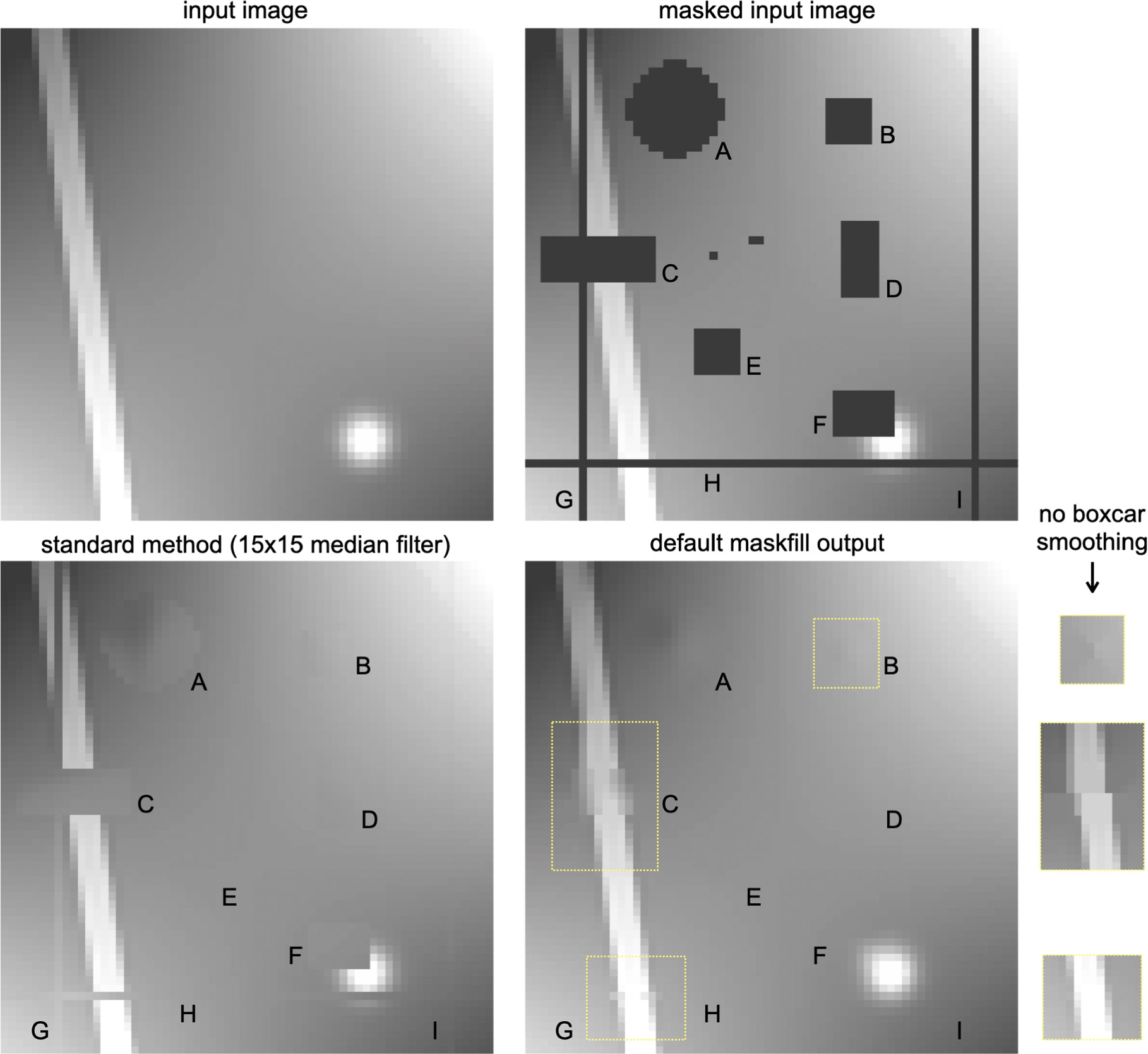
The method is first applied to an artificial image of 64 × 64 pixels, with a smoothly varying background, a linear feature, and a star. Regions of varying shapes and sizes are masked, including a column, a row, and several rectangles (see Figure 3). Results from a standard method to fill in the mask are shown in the bottom left panel of Figure 3. Here a 15 × 15 pixel median filter was applied to the image, excluding all masked pixels. The size of the filter just exceeds the dimensions of the largest masked region. As expected, all masked regions, including those that intersect the linear feature (C) and the star (F), are filled with the local background. This fill method works well for regions that are far away from objects: B, D, E, and portions of the masked row (H) and columns (G, I).

Figure 3. Application to a synthetic image with a variety of structures and masks. The input image and the masked input image are shown at the top. A standard method for filling in masked regions, using a 15 × 15 pixel median filter applied to unmasked pixels, is shown at lower left. The lower right panel shows the maskfill output. The masked row and columns (G, H, and I) are nearly identical to the input image, and both the star (F) and the linear feature (C) are reconstructed reasonably well. Insets at right show the effects of setting the --nosmooth flag in maskfill.
Download figure:
Standard image High-resolution imageThe output from maskfill is shown in the lower right panel. The code performs equally well as the simple 15 × 15 median filter in empty regions, and much better where the masks intersect objects. The masked portions of the linear feature (C) and the star (F) are reconstructed fairly well. The reconstructions of the masked row and columns are nearly perfect; for features with a width of 1 or 2 pixels, such as bad pixels, hot pixels, bad columns, and many cosmic rays, the code reduces to a straightforward (and optimal) interpolation of the locally adjacent pixels.
As noted above, the default settings of maskfill include a 3 × 3 boxcar smoothing at the end. The insets at right show the effects of turning this smoothing off (with the --nosmooth flag). The reconstruction of the sharp linear feature is improved, at the cost of having a faint X-pattern in B.
4.2. Cosmic Ray Replacement
While maskfill cannot be used to detect cosmic rays, it is well-suited to replacing them with plausible values after they are found. A test image was created by adding actual cosmic rays (identified in an HST WFPC2 image) to a deep HST UVIS image (from program GO-17301). Three example galaxies are shown in Figure 4. The performance of maskfill is compared to that of l.a.cosmic (van Dokkum 2001). After identifying cosmic rays, l.a.cosmic produces a cleaned image by replacing masked pixels with the median of neighboring pixels, using a fixed 5 × 5 filter. This size is adequate for cosmic rays, as they are always narrow in at least one-dimension.

Figure 4. Replacement of cosmic rays, in 1 2 × 17 sections of a deep HST image. The cosmic rays were obtained from an independent image and added to the drizzled data. The maskfill code performs slightly better than the fill routine in l.a.cosmic (van Dokkum 2001), although differences are small.
Download figure:
Standard image High-resolution imageThe performance of maskfill is indistinguishable from that of the fill step of l.a.cosmic in the vast majority of cases, with both methods producing excellent results. In the rare cases where there is a difference, maskfill performs better. An example is shown in the bottom panels of Figure 4: a cosmic ray covers the center of a compact galaxy, and the 5 × 5 filter of l.a.cosmic is too large to reconstruct the affected pixels. For optimal results, maskfill can simply be run after l.a.cosmic, using the original image and the mask that l.a.cosmic produces as inputs.
4.3. Sections of M51
For a more challenging test, the iconic IRAF 512 × 512 pixel image of M51 was degraded by adding 3000 wide and long cosmic ray-like objects. A few bright stars in the image were also masked. In Figure 5 the maskfill reconstructions of several regions are compared to the unmasked input. The filled images are very similar to the original images, even in cases where several masks intersect. The bottom row of Figure 5 shows a masked star. The filled-in mask is a plausible continuation of the surrounding emission.

Figure 5. Demonstration on the IRAF M51 image, with a mask containing 3000 thick cosmic ray-like objects. The maskfill reconstructions, with default parameters, are shown in the middle column, with the original images at right. The bottom row shows a masked star.
Download figure:
Standard image High-resolution image4.4. Wide Field Low Surface Brightness Imaging
The detection of low surface brightness (LSB) features, such as tidal tails and diffuse galaxies, can be challenging, particularly in crowded fields. In Figure 6 we show cutouts of a wide-field continuum-subtracted Hα image of the M81 group, taken with the Dragonfly Spectral Line Mapper pathfinder (Pasha et al. 2021; Lokhorst et al. 2022). A typical contaminant in continuum-subtracted imaging are residuals of bright stars, as saturation, color terms, and imperfect PSF matching can lead to strong residuals. These residuals are masked in the middle panel. The image size (3600 × 2500 pixels) and the size of each mask (∼102 pixels) make this a taxing example of a maskfill's use case.

Figure 6. Cutout of a Wide-field narrowband Hα image of M81 and M82 obtained with the Dragonfly Spectral Line Mapper pathfinder instrument (Pasha et al. 2021; Lokhorst et al. 2022). The size of this image is (3600, 2500). Top: image after continuum subtraction, with stellar residuals due to saturation and differences in the PSFs. Center: masks for the residual star locations. Individual masked objects often cover ∼102 pixels. Bottom: maskfill output, highlighting the way large scale features can be more easily identified. Note that due to the significant size of each mask (in pixels), maskfill was run with a window size of 11. Despite the size and number of masks, maskfill completed in ∼30 s.
Download figure:
Standard image High-resolution imageThe bottom panel shows that the code performs well, producing a very clean image that makes large, nearly degree-scale LSB features easy to see by eye. In this example the window size was set to 11 instead of the default 3 pixels, as the masks do not always cover the residuals completely. The runtime was ∼30 s. We discuss the overall runtime performance of maskfill further in Section 5; future work aims to bring it down further via the use of optimized just-in-time compilation packages.
5. Comparisons and Performance
Here we assess the filling quality of maskfill compared to other standard interpolative routines, including nearest-neighbor, linear, cubic, and biharmonic interpolation.
First, we assess the rms error (RMSE) and median absolute deviation (MAD) between an un-destructed image and a masked image across the various methods, taking three reasonably separated cases: the "cosmic ray case," in which there are many small masks of ∼few pixels each, the "star" or "artifact" case, in which there are several medium-sized circular masks, and the "large mask" case. We use the M51 image for this test, and to avoid the (expected) residuals from foreground stars and the center of the galaxy dominating the comparison, we choose an arbitrary, quiet region in the galaxy outskirts for this test. We conduct all tests both on the original image, which has very high signal-to-noise ratio (S/N), as well as a version for which Gaussian noise has been added to artificially lower the S/N.
The results are presented in Figures 7, 8, and Table 1. We find that maskfill generally has the lowest RMSE and MAD across these tests, and in particular, is robust against catastrophic fits in the case of noisy images. For the "noiseless" case (Figure 7), maskfill has generally the best statistics, performing particularly well in the case of the very large mask. Several other methods, such as the linear and biharmonic spline, produce reasonably consistent residuals (though less so for the large mask).

Figure 7. Comparison of different interpolation schemes. Top: interpolations in the presence of many small masks (e.g., the case of cosmic rays). We show the original image (masked version below), followed by the outputs from maskfill, nearest-neighbor, as well as linear, cubic, and biharmonic splines. The bottom panels show the residuals normalized to the original image, and the rms and MAD are shown. Middle: same as top panels, but for 13 small masks (e.g., the star-like case). Bottom: a single, huge mask. In this case, maskfill was run with a window size of 5 pixels. Overall, we find that maskfill outperforms or matches the other methods presented in all cases, and is particularly more robust for large masks. The metrics in this figure can also be found in Table 1.
Download figure:
Standard image High-resolution image
Figure 8. Interpolation schemes in the presence of noise, with the same mask examples presented in Figure 5. Here, we add Gaussian noise to the M51 image with a scale ∼the median pixel value, simulating a low S/N image. The quoted rms and MAD have been normalized to the scale of the added noise for easier comparison to the noiseless test. We find that in the presence of noise, maskfill performs significantly better than the other interpolation methods both in rms and MAD, as well as visually (particularly when the mask gets large).
Download figure:
Standard image High-resolution imageTable 1. Interpolation Performance Comparison for the Three Test Mask Cases and Two Noise Scenarios
| Method | CRs | CRs + Noise | Star Masks | Star Masks + Noise | Large Mask | Large Mask + Noise |
|---|---|---|---|---|---|---|
| Maskfill | 2.79 (1.61) | 1.06 (0.71) | 3.08 (1.92) | 1.10 (0.69) | 9.97 (4.98) | 1.10 (0.74) |
| Nearest Neighbor | 3.84 (2.00) | 1.40 (0.95) | 3.82 (2.00) | 1.39 (0.94) | 13.2 (5.00) | 1.45 (0.97) |
| Linear | 6.10 (1.67) | 1.23 (0.83) | 3.44 (1.96) | 1.27 (0.85) | 9.47 (5.51) | 1.35 (0.92) |
| Cubic | 6.43 (2.01) | 1.56 (1.01) | 5.11 (3.00) | 2.79 (1.80) | 41.6 (24.3) | 19.2 (15.0) |
| Biharmonic Spline | 2.89 (1.67) | 1.25 (0.84) | 3.28 (2.02) | 1.48 (1.05) | 13.7 (9.86) | 2.60 (2.00) |
Note. Values are rms errors (RMSE), with the median absolute deviation (MAD) in brackets. The nearest-neighbor, linear, and cubic routines are from the scipy.interpolate package, while the biharmonic spline is from the scikit-image package.
Download table as: ASCIITypeset image
For the noise-added images, the differences become more stark—maskfill has considerably lower residuals than the other methods. Particularly as the masks get larger, the other methods produce artifacts and bleed-through features which render the fills mostly unusable. Conversely, the medians-of-medians iterative routine used by maskfill is robust against the presence of edge pixels which are far from the center of the distribution.
This point is emphasized further when examining real, low S/N data. In Figure 9, we show a 750 × 750 cutout of the M81 image from Figure 6, comparing the biharmonic output (left) to that of maskfill (right). There are no tuning parameters for the biharmonic spline as implemented in scikit-image. In these situations, maskfill appears to be considerably more robust, with medians tamping down on outlier pixels and their effect limited to the track of several radial pixels into the mask (beyond which further medians tend to dampen them out). The poor inpainting from the spline can be reasonably explained by a combination of the two effects described above: the noise of the image, and the large size of the masks, both of which contribute to the inability of the algorithm to appropriately infill the masked pixels without tuning. We note that much better results can be obtained with biharmonic splines that are tuned to the size of the largest masks (see Popowicz & Smolka 2015).

Figure 9. Comparison of the infilling between biharmonic spline (left) and maskfill (right) on a cutout of the Dragonfly M81 narrowband image. Aspects of the pixel distribution of the image appear to cause catastrophic outputs from the spline interpolation, while the maskfill algorithm is mostly unaffected. This is because a simple localized median effectively downweights outliers, and as the iterations work inward into the mask, further medians quickly damp out the effect of aberrant pixels near the mask edge. For example, the large mask in the upper left has strongly negative values in the biharmonic spline restoration due to strong "bleed-through" of a small set of discrepant pixels in the upper right hand corner just outside of the mask.
Download figure:
Standard image High-resolution imageWhile it is beyond the scope of this paper to perform a comprehensive speed analysis across methods (particularly given the fact that there are different implementations of the other interpolations), we do carry out some simple tests of maskfill's speed to inform use cases users might have. The runtime of the code scales directly not with the image size, but with the total number of masked pixels and the size of the average mask in the image. The former is because the code executes a loop over all (fillable) masked pixels in each iteration, i.e., the edges of all masked regions, and the latter determines the number of infilling iterations required for the algorithm to complete. The detection of fillable-masked pixels as the start of each iteration is a fast convolution which does not significantly impact the runtime; thus, in total, we expect the runtime to scale approximately linearly with the number of masked pixels.
We assess the speed scaling of maskfill using the large M81 image and its associated mask, starting with a 100 × 100 cutout and expanding sequentially to a 2000 × 2000 cutout. The masks in this image are generally uniformly sized and spaced, so progressively larger cutouts have more masked pixels. Figure 10 demonstrates that the runtime scales approximately linearly with number of masked pixels as expected; a fit to the runtimes gives .
.

Figure 10. Maskfill runtime (in seconds) as a function of the number of masked pixels in the image, with a linear fit. In these examples the masks are distributed randomly, which means that the number of masked pixels scales directly with the size of the image. We find a fit coefficient of 1.03, demonstrating that the relationship is indeed linear. The normalization depends on the typical size of individual masks and the hardware that is used; for this particular example the fill speed is ≈5 × 10⁴ pix s−1.
Download figure:
Standard image High-resolution image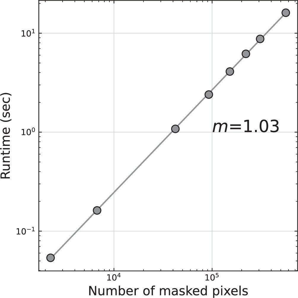
The normalization depends on the number of iterations (and therefore on the typical size of individual masks) as well as the hardware that is used. In typical cases the fill speed will be ∼105 pix s−1 for small masks such as bad pixels and cosmic rays, dropping to lower speeds for masked stars and galaxies.
Because of the minimal dependencies and use of matrix-dominated operations, maskfill is well suited to current techniques for just-in-time compilation via, e.g., the jax or numba frameworks, potentially providing order-of-magnitude runtime improvements for larger images/larger masks; active development in this direction is underway.
6. Conclusions
This paper describes maskfill, a new method for filling in masked emission in astronomical images. The method is encapsulated in Equation (1), and implemented as an iterative inward extrapolation of the edges of masked regions. It is available as a Python package through github and the PyPI. Although maskfill.py has several optional parameters, no tuning should generally be necessary: the code works on masks of arbitrary shapes and sizes, always beginning with the pixels that are closest to the edge.
Several caveats and limitations should be mentioned. Even though the algorithm is well-defined it is difficult to assign an uncertainty to the filled-in values. The formal per-pixel noise decreases with d, the distance to the edge of the mask, according to  , with σorg the per-pixel noise outside of the mask. However, the reliability of the reconstruction depends on the likelihood of encountering features that do not extend beyond the mask boundaries. The bottom row of Figure 5 is a good example of this: if the circular mask had been created to cover a defect, the reconstruction would have entirely missed the star at that location. Fortunately, most detector defects and cosmic rays are on scales of a few pixels, where the code is reliable and its behavior is predictable. Larger masks are often created to mask objects, and in those cases the whole point is not to match reality but to replace the masked region with something that fits in with its surroundings.
Another limitation is the characteristic cross pattern that arises on smoothly varying backgrounds, particularly within square regions. This is inherent in the method: the extrapolation begins on the four edges and then works its way inward. When the filled-in pixels finally meet in the center, they each represent a different edge, with almost no knowledge of the other three edges. The boxcar smoothing step at the end reduces this artifact, at a cost of a slight loss of resolution. This trade-off is illustrated in Figure 3.
That said, we find maskfill to be a relatively fast, intuitive, and robust method for mask infilling which relies only on the images at hand.
Acknowledgments
We thank the referee, Adam Popowicz, for insightful comments and for the suggestion to compare the method explicitly to other interpolation schemes. The maskfill code makes use of NumPy 1 (Walt et al. 2011); SciPy 2 (Virtanen et al. 2020); and Astropy 3 (Price-Whelan & Astropy Collaboration 2018). Several example images were created with IRAF, 4 the Image Reduction and Analysis Facility (Tody 1986, 1993). Support from NSF grant AST-2108341 is gratefully acknowledged.
Footnotes
- 1
- 2
- 3
- 4