

Abstract
The Small AUtonomous Robotic Optical Nightwatcher (SAURON) is an autonomous telescope consisting of an 11-inch Celestron Nexstar telescope on a SoftwareBisque Paramount ME II in a Technical Innovations ProDome located at the MIT George R. Wallace, Jr. Astrophysical Observatory. This paper describes the construction of the telescope system and its first light data on T-And0-15785, an eclipsing binary star. The out-of-eclipse R magnitude of T-And0-15785 was found to be 13.3258 ± 0.0015 R magnitude, and the magnitude changes for the primary and secondary eclipses were found to be 0.7145 ± 0.0515 and 0.6085 ± 0.0165 R magnitudes, respectively.
Export citation and abstract BibTeX RIS
1. Introduction
The Massachusetts Institute of Technology (MIT) George R. Wallace, Jr. Astrophysical Observatory (WAO) operates seven permanent telescopes and eight portable telescopes that are used by MIT students and staff for outreach, teaching, and research purposes. WAO is located at 42.61° latitude and −70.51° longitude in Westford, Massachusetts.
In general, telescopes fall into four operational categories: manual, GoTo, remote, and robotic. Manual telescopes require the observer to physically point the telescope at the target object. A GoTo telescope connects to software that is able to point the telescope. However, the observer must still be at the same location as the telescope in order to fine-tune the pointing. Remote telescopes can be operated from a different location through a computer that operates the telescope and the dome. The observer still needs to monitor the telescope while taking data. Robotic telescopes can follow a script to collect data, but they are limited in their ability to adjust to new information such as bad weather, poor signal, or new target priorities.
WAO has been actively working toward automating their observations since the observatory was constructed in 1971. The first telescope built at WAO was designed specifically to be operated from a separate control room; remote telescopes were rare in the 1970s. Now, WAO has two 14-inch manual telescopes, two 14-inch robotic telescopes, one 16-inch GoTo telescope, one 24-inch robotic telescope, and one new 11-inch autonomous telescope. The two remote telescopes can be converted to autonomous telescopes by adding additional hardware inputs (weather and local sky conditions) and software to interpret this information, resulting in decisions about how and when to observe. The telescope described in this work, the Small AUtonomous Robotic Optical Nightwatcher (SAURON), is an autonomous telescope. SAURON was built and characterized from 2014 May to 2017 February.
Small telescopes, less than a meter in size, are located at hundreds of universities for teaching and research purposes. These telescopes allow students to experience astronomy hands-on. Although these telescopes are small, they are especially useful for followup projects that need large amounts of observing time and modest precision (Dunham et al. 2014). However, observations can be overly time-consuming for an experienced observer, as data collection conflicts with a normal working schedule. As a result, many small telescope hours go unused at university observatories. Autonomous telescopes are the perfect innovation to connect the availability of small telescopes with research requiring a long time baseline. For example, confirming planets found with NASA's Transiting Exoplanet Satellite Survey (TESS) mission would be an ideal project for small autonomous telescopes since the observations require a long baseline and the stellar targets are too bright for large telescopes with small fields of view (Hall 2015).
This project has even larger implications for alleviating observatory location constraints. For example, WAO is located in an area with abundant cloudy nights, humid summers, and light pollution from surrounding cities. Because an autonomous telescope does not need human interaction, the physical telescope can be built far away from the location of the observers. Therefore, the next WAO telescope can be located in a remote location which has optimal weather conditions.
Section 2 describes the facility and Section 3 describes the first light data used to characterize SAURON.
2. Telescope Components and Construction
2.1. Telescope, Mount, and Dome Components
The optics system is currently a repurposed 11-inch Celestron NexStar GPS optical tube4 , mounted with a dovetail to a SoftwareBisque Paramount ME II5 (optical tube and mount specifications located in Tables 3 and 4). This preliminary optical tube was used to test the autonomous abilities of the other components. Once the system has been fully tested, the optics will be upgraded to an 17-inch tube so that fainter targets can be observed. The mount was chosen because it is capable of robotically pointing to target locations and has instrument capacity for 109 kg (Bisque), which is compatible with both the preliminary 11-inch telescope and the final 17-inch telescope.
The Paramount is mounted on a custom-made steel pier designed by T. Brothers and fabricated by machinists at the MIT Haystack Observatory. The pier is located in the center of the dome and is bolted to a 18'' wide, 6'' tall, concrete cylinder with an internal steel pipe, decoupled from the concrete pad. This concrete pier is resting on underlying bedrock and stabilized by the surrounding concrete so that surface vibrations do not affect the telescope. More information about the optics and mount specifications can be found in Appendix
The dome used for this project is a Technical Innovations 10-foot ProDome. This dome was chosen because it can operate during all four seasons in Massachusetts and can take conditional commands from the weather monitoring systems and location commands from TheSkyX via ASCOM. The dome is mounted 24 inches above the ground on top of two support rings; the telescope mounted inside matches the shutter height and can observe in all directions. The minimum observable altitude due to the treeline is 30 degrees in the North, 10 degrees in the South, and 20 degrees in the East and West.
2.2. Instrumentation and Software
Three different charge-coupled devices (CCDs) were used while testing: Portable Instrument for Capturing Occultations (PICO) (Lockhart et al. 2010), Quantum Scientific Imaging (QSI) 683s CCD (Q. S. Imaging)6 , and Santa Barbara Instrument Group (SBIG) ST-7XME Detector (S. A. Instruments)7 (detector specifications located in Table 5). The SBIG ST-7XME is currently mounted onto SAURON; we plan on upgrading this camera to a Finger Lakes Instrumentation CCD Camera in the future.
Other necessary instruments include the Starlight Xpress USB filter wheel, Custom Scientific Johnson/Cousins Photometric BVRIC filters, the Integrated-Control Temperature Compensating Focuser (TCF-Si), and Orion 80 mm refractor finderscope (Appendix
The essential software for a remote telescope includes TheSkyX Professional Edition (equipment control), MasterSync (GPS time base), Digital Dome Works (dome setup) and various equipment drivers. CCDWare's CCDAutoPilot is required for automation.
It is essential to have accurate pointing and tracking for an autonomous telescope. MasterSync supplies the time from a GPS-based Network Time Protocol server to result in precise time recordings for each image and precise telescope pointing. TheSkyX uses a TPoint Add On to initially polar align the telescope and to subsequently point the telescope. TheSkyX performs a periodic error correction to improve the tracking of the telescope by taking into account the locations of the mount motor wheels. TheSkyX also combines all of this information in ProTrack to further improve tracking.
2.3. Dome and Telescope Construction
The site was first prepared by clearing unused telephone poles and nearby trees, digging a drainage trench, and running ethernet cables to the concrete pier. Removal of an original damaged concrete pier was done by Legace of Westford, MA. Electrical work was done by L. Pothier, J. Byford and T. Brothers. Next, the steel pier was attached to the existing concrete pier to raise the optical tube up to match the 36-inch dome base.
To construct the dome, the pieces were first loosely bolted together, placed on the concrete pad, and circularized. The dome is 119.5 inches in diameter and level to 0.3 degrees. The dome ring was then attached to the pad with 24 half-inch lag screws and lag shield anchors. Next, two pairs of dome roof quarters were bolted together. Then, those two halves were attached to the dome support ring with the three shutter pieces in between (Appendix
To automate the shutter, cables were strung along the edge of the shutter, attached to the motor in the back, and tensioned with shutter clamps. The shutter is a three-piece interlocking system that opens from one side, resulting in a 2-foot window from the southern horizon to 70 degrees above the northern horizon. Shutter testing was performed with the hand paddle that is wired directly to the control board in the dome and with the homing switch on the outside of the dome. Afterwards, the dome was paired with the telescope mount through TheSkyX Professional Edition to match the shutter opening with the telescope pointing location.
Once the dome was operational and fully sealed off from the weather, the telescope components were installed. First, the Paramount ME II was bolted to the steel pier and leveled using the microlevelers at the base of the mount. The mount is level to within 0.1 degrees. Afterward, all of the other instrumentation (listed in Section 2.2) were installed in the dome. Finally, a wooden platform was built around the base of the telescope mount, power cables were threaded through the mount, and exterior cables were bundled together.
Afterward, data were collected to test and calibrate the system as a robotic telescope. At the same time, dome movement and telescope pairing troubleshooting were performed. Finally, CCDAutoPilot was installed to communicate between the weather system and telescope system; to control dome and telescope movement; and to automate the observations.
2.4. Key Challenges
2.4.1. Weatherproofing the Dome
Weatherproofing the dome is necessary to protect the instruments and to allow the dome to rotate smoothly. To seal the dome, caulk was applied both between each of the sections during construction and also applied externally in all crevices afterwards. Foundation sealer was required to seal the dome to the concrete.
To seal beneath the door while allowing the door to open, we applied a 2-inch high barrier of foundation sealer on the inside of the door. For this barrier to work with heavy snowfall, the concrete pad needs to be shoveled frequently.
2.4.2. Dome Rotation
Initially, there were several factors that caused the dome to either get stuck or lose its position, including dome support ring (DSR) warping, ice intrusions, and dust coating the dome sensors. This problem is particularly important because the shutter can only operate when the dome is in the home position. Therefore, if the rotation fails, the shutter will remain open and the instruments can be harmed.
When a stuck point occurs, TheSkyX continuously sends commands to the dome. The dome status switches between "Ready" and "Slewing to Target" and will not accept more commands. Digital Dome Works (DDW) can be used to rotate through some problem areas; however, manual pushing of the dome roof is necessary in extreme cases. Dome rotation errors cause the drive motors to work harder and thus scrape off traction material from the dome ring. Dome movement necessitates thorough caulking, periodic reapplication of traction material, regular inspections of the dome sensors, and removal of dust buildup.
To improve dome reliability, we shortened the motor springs to improve wheel to dome contact, adjusted dome support wheels to make more consistent contact, and modified the dome screws to prevent scraping. We also developed a maintenance routine to clean the dome home contacts and the dome position azimuth sensor to prevent position loss. We are currently developing a dome azimuth sensor replacement that is less prone to error.
2.4.3. Dome Home Sensor
The dome uses the "home" position to reset its position encoders, to allow the door to open, and to power the shutter. The "home" position is determined by the completion of a circuit between two copper rings on the side of the dome and two metal plates on the dome support ring (Appendix
3. First Light on T-And0-15785
3.1. Data Collection and Analysis
To demonstrate the scientific capabilities of SAURON, eight nights of data were collected on T-And0-15785, an eclipsing binary star, from 2015 January to March. T-And0-15785 has a baseline R magnitude of 13.380, a period of 0.7311466 days, and is located at 01 03 13.82 RA and +47 59 46.6 DEC in the constellation Andromeda (Devor et al. 2008). The Simbad identifier for T-And0-15785 is UCAC2 47685084 (S. A. D. Center). Additional measurements of T-And0-15785 were taken using a robotic 14-inch telescope at WAO over 2014 September and October. A summary of all observations can be found in Table 1.
Table 1. Summary of Observations
| Date | Conditions | Camera | Filter | No. of Images |
|---|---|---|---|---|
| 2014 Sept. 19 | Clear | SBIG-ST7 | R | 20 |
| 2014 Sept. 26 | Clear, high humidity | SBIG-ST7 | R | 15 |
| 2014 Oct. 8 | Increasing clouds | SBIG-ST7 | R | 10 |
| 2015 Jan. 7 | Clear, full moon | PICO | Unfiltered | 35 |
| 2015 Jan. 10 | Clear, partial moon | PICO | R | 20 |
| 2015 Jan. 19 | Clear to cloudy | PICO | Unfiltered | 560 |
| 2015 Jan. 20 | Patchy clouds to clear | PICO | Unfiltered | 85 |
| 2015 Jan. 22 | Clear, crescent moon | PICO | Unfiltered | 1005 |
| 2015 Jan. 23 | Clear to cloudy | PICO | Unfiltered | 270 |
| 2015 Feb. 3 | Clear, full moon | QSI | Unfiltered | 165 |
| 2015 Mar. 3 | Clear | SBIG-ST7 | Unfiltered | 45 |
Download table as: ASCIITypeset image
To produce astronomical light curves, the data were first reduced using AstroImageJ, with flat, dark, and bias images. Then photometry was performed on the reduced data to find the apparent magnitude of T-And0-15785 using field stars from the USNO-A2.0 Catalogue et al. (Monet 1998).
3.2. T-And0-15785 Results
The data were folded over the rotational period of 0.7311466 (Devor et al. 2008) to result in a light curve (Figure 1). Data from January 7 and 10 were not included in the plot due to the repeated breaks in the data collection to troubleshoot problems with the camera shutter and the dome movement. The baseline was found to be 13.3258 ± 0.0015 R mag by finding the average value of the data taken on 2014 September 19, September 26, and October 8. These data were used because they contained baseline data, had the lowest scatter, and were all observed using the R filter. The unfiltered data were then shifted to fit the baseline. Shifts are summarized in Table 2.

Figure 1. T-And0-15785 light curve (top) and residuals (bottom). Lorentzian eclipse fits and baseline are shown as a solid black line.
Download figure:
Standard image High-resolution imageTable 2. Magnitude Shifts for Unfiltered Data
| Date | Magnitude Shift |
|---|---|
| 2015 Jan. 19 | 0.161 |
| 2015 Jan. 20 | 0.198 |
| 2015 Jan. 22 | 0.221 |
| 2015 Jan. 23 | 0.279 |
| 2015 Feb. 3 | 0.256 |
| 2015 Mar. 19 | 0.223 |
Download table as: ASCIITypeset image
The Lorentzian fit was found for the primary eclipse using the data from 2015 February 3 and 2015 March 19. The complete fit assumed a symmetric eclipse. The delta magnitude for the primary eclipse is 0.7145 ± 0.0515 R mag over 0.25 ± 0.01 days. The Lorentzian fit was found for the secondary eclipse using the data for 2015 January 19 and 22, and 2014 October 8. The delta magnitude for the secondary eclipse is 0.6085 ± 0.0165 R mag over 0.254 ± 0.005 days. These values are consistent with Devor et al. (2008), who reports the delta magnitude for the primary and secondary eclipses as 0.703 and 0.632 mag respectively (Devor et al. 2008). Finally, we find the epoch for the primary and secondary eclipses to be 2457101.5296 ± 0.0053 and 2457042.6366 ± 0.0009 days, respectively.
4. Conclusion
The Small AUtonomous Robotic Optical Nightwatcher (SAURON) was built, characterized, and automated at the MIT George R. Wallace, Jr. Astrophysical Observatory. SAURON is an 11-inch Celestron Nexstar telescope on a Software-Bisque Paramount ME II housed in a Technical Innovations ProDome. Specifications are listed in Appendix
SAURON will increase the efficiency of data collection at WAO. It will encourage long-term projects to be pursued and save countless hours of observer time. This project has initiated the transition of two of the existing telescopes at WAO from robotic to autonomous. As a long-term goal, WAO plans to build an autonomous telescope in a remote location with optimal weather patterns to optimize data collection. In general, autonomous telescopes can improve the data collection potential of many teaching and research observatories.
This research was supported by the George R. Wallace Jr. Astrophysical Observatory. We also thank Jane Connor for advice and assistance.
Appendix A: Component Specifications
The tables in this appendix provide the component specifications for the optical tube, mount, and three detectors used for this project.
Table 3. Optical Tube Specifications (Celestron)
| Optical Tube | Celestron NexStar GPS |
| Aperture Diameter | 11 in (279 mm) |
| Focal Length | 110 in (2800 mm) |
| Focal Ratio | f10 |
| Weight | 65 lbs. |
| Optical Design | Schmidt-Cassegrain |
| Limiting Magnitude | 14.7 (using SBIG CCD) |
Download table as: ASCIITypeset image
Table 4. Mount Specifications (Bisque)
| Mount | SoftwareBisque Paramount ME II |
| Pointing Accuracy | 30 in. (with Tpoint + supermodel) |
| Instrument Capacity | 240 lbs. |
| Maximum Payload | 480 lbs. |
| Counterweights used | 60 lbs. |
| Root-Mean-Square Pointing | 14.5 arcsec |
| Population Standard Deviation | 15.12 arcsec |
| Maximum Slew Rate | 6 degrees/second |
| Default Slew Rate | 5.4 degrees/second |
Download table as: ASCIITypeset image
Table 5. Detector Specifications
| PICO (Lockhart et al. 2010) | QSI (Q. S. Imaging) | SBIG (S. A. Instruments) | |
|---|---|---|---|
| Model | ML261E-25 | 683s | ST7-XME |
| Field of View | 12' × 12' | 20.95' × 15.77' | 8.033' × 5.35' |
| Image Scale (in./pixel) | 1.4 | 0.378 | 0.630 |
| Pixel array (pixels) | 512 × 512 | 3326 × 2504 | 765 × 510 |
| Pixel size (μm) | 20 × 20 | 5.4 × 5.4 | 9 × 9 |
| Read Out Rate | 1.0 or 2.8 MHz | 0.8 or 8 MHz | 0.417 Hz |
| Gain (e−/ADU) | 2.06 or 1.90 | 0.5 or 1.1 | 2.6 |
| Read Noise (e−) | 13.6 | 8 | 15 |
| Exposure Times (s) | 0.1–3600 | 0.12–3600 | 0.11–3600 |
Download table as: ASCIITypeset image
Appendix B: Reference Pictures
This appendix provides reference pictures of the dome and telescope setup.
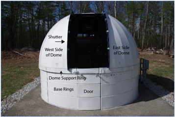
Figure 2. Telescope system.
Download figure:
Standard image High-resolution image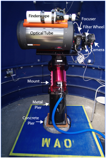
Figure 3. Dome frontview.
Download figure:
Standard image High-resolution image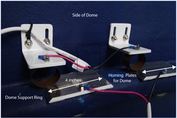
Figure 4. Dome homing plates.
Download figure:
Standard image High-resolution image
Footnotes
- 4
Celestron Cpc 1100 gps (xlt) Computerized Telescope: http://www.celestron.com/browse-shop/astronomy/telescopes/cpc-telescopes/cpc-1100-gps-(xlt)-computerized-telescope.
- 5
Paramount ME II: http://www.bisque.com/sc/pages/ParamountMEII.aspx.
- 6
QSI 600 Series—Cooled CCD Cameras: http://www.qsimaging.com/683-overview.html.
- 7
S. A. Instruments Operating Manual CCD Camera Models st-7xe/xme, st-8xe, st-9xe, st-10xe/xme, and st-2000xm/xcm with High-speed USB Interface: http://www.sbig.de/sbig-history/download/katalog/catalog.pdf.