


Abstract
Two-dimensional topological photonic crystals have rapidly emerged as a recent and fascinating branch of photonic research. However, most of them were limited to a specific type of polarization, TE or TM polarization. Here, we explored the dual-polarization topological phases in two-dimensional magnetic photonic crystal (PC) which are composed of ferrite rod clusters in the plasma background. Under the perturbations of the bias magnetic field and/or the cluster distortion in the unit cell, the PC exhibited dual-polarization topological phases, including the quantum Hall (QH) phase, the higher-order quantum spin Hall (HO-QSH) phase and the conventional insulator (CI) phase. We studied the topological nature of these phases by the Wilson loop, Chern number, and unidirectional edge states. Intriguingly, we showed that the HO-QSH phases could present in PC of C3v symmetry instead of being restricted to C6v symmetry. The lower symmetry enlarges the gap in the edge states, which helps for the emergence of corner states. By continuously deforming the unit cell configuration, we demonstrated the phase transition in the system was dual-polarization. Our results extend the topological phases in the PCs and pave the way for the dual-polarization topological devices and their applications.
Export citation and abstract BibTeX RIS

Original content from this work may be used under the terms of the Creative Commons Attribution 4.0 licence. Any further distribution of this work must maintain attribution to the author(s) and the title of the work, journal citation and DOI.
1. Introduction
Like topological insulators in solid matter, topological phases in photonic insulators have received a lot of attention. The interest is partly fueled by the incredible promise that the photonic insulators support topologically protected edge states at which the surface waves propagate unidirectional and robustness against defects at the interfaces [1–10]. Different topological phases are found in photonic systems, including the quantum Hall (QH) phase [1–4, 6], quantum spin Hall (QSH) phases [11–23], quantum valley Hall (QVH) phase [24–37] and higher-order topological phases [38–43]. Symmetries play a crucial role in the development of topological phases. For example, the QH phase needs to break time-reverse symmetry (TRS) [1, 2], and the QSH phase requires the C6v symmetry [11, 12]. More recently, by gapping out the topological edge states, the higher-order topological insulators are introduced in QSH and QVH phases [42, 43]. These topological phases not only support the one-dimensional pseudo-spin edge states, but also the zero-dimensional corner state, i.e. they have the unconventional bulk-boundary correspondence. When multiple symmetry simultaneously are broken in one photonic system, different topological phases may appear. The phase transitions are due to the competition of mass terms in the system's Hamiltonian. For example, the topological phase transitions in hexagonal cluster PCs result from the variation of TRS and crystalline symmetries [14, 20]. The phase transition is also found in the systems with TRS and parity symmetries [25], or the TRS and inversion symmetries [34]. Though a large number of topological phases and phase transitions are demonstrated in the 2D system, they are all limited to a single-polarization. Then, it is natural to explore the possible existence of dual-polarization topological phases and the phase transition.
In this paper, we will show that the dual-polarization topological phases can present in the magnetic PC. By embedding ferrite rods in the plasma background material, the magnetic PC has the full bandgap that supports the dual-polarization phases, including the higher-order quantum spin Hall (HO-QSH) phase, the QH phase, and the conventional insulator (CI) phase. These topological phases are proved by the Wilson loop, Chern number, and unidirectional edge states. When bias magnetic field and the distortion of the rods' position are applied in the structure simultaneously, topological phase transition will take place, which are also dual-polarization. We demonstrate that the HO-QSH can present in the magnetic PCs with C3v symmetry, not necessarily to be C6v symmetry as in previous works [11–23]. The HO-QSH and CI phases in the PC of C3v symmetry will enlarge the gap in the edge states, which helps to create corner states and separate them from bulk and edge states. The PCs with C3v symmetry may provide more degrees of freedom than that with C6v symmetry for designing topological phases.
2. Dual-polarization topological phase
For two-dimensional (2D) systems, any electromagnetic (EM) modes can be separated into two decoupled modes (or polarizations), the TE {Hx
, Hy
; Ez
} and TM {Ex
, Ey
; Hz
} modes. In general, the band structures for these two modes are usually different in 2D PCs. To have the two modes with a common bandgap, we consider the 2D PC as shown in figure 1(a). It is composed of triangular-shaped ferrite rods embedded in the plasma material background. The rods are optimized by the Nelder–Mead method [45, 46] to widen the common bandgap. The triangular rod has a side length l = 4.8 mm and a blending diameter d = 3 mm. The unit cell of the PC is composed of a hexagonal rod cluster separated into two subsets (in red and blue). The radius R1 (R2) measures the distance between the center of the red (blue) rod and the unit cell center. The PC is in a hexagonal lattice and the lattice constant is a =  mm. Suppose the ferrite material is yttrium iron garnet (YIG) whose relative permittivity is εr = 12 and the saturation magnetization is Ms = 1884 Gauss [6]. For the plasma background material, the electron density is ne = 0.4547 × 1012 cm−3 [44].
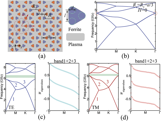
Figure 1. (a) Schematic of 2D PC structure. The ferrite rods are embedded in the plasma background. (b) Band structures of PC with R = a/3 for TE mode under zero external bias field. (c) and (d) The band structure for TE and TM modes under bias magnetic field H = 1000 Oe. For both polarizations, Berry phase of the three lowest bands reveal that the gap Chern number is Cg = 1. The green regions denote the common frequency range for both TE and TM modes.
Download figure:
Standard image High-resolution imageIn order to explore the possible existence of topological phases in the PC, we first calculate the band structure of the PC at R1 = R2 = a/3 (the honeycomb structure) under zero bias magnetic field. Figure 1(b) shows the band structure of TE mode. There is a four-fold degeneracy point at the high symmetric Γ-point. When an external perturbation is applied to the PC, a bandgap will be open at the degeneracy points. Here, the external perturbation can be the deformation of rods' position in the unit cell or the external bias magnetic field.
When the perturbation is the external bias magnetic field, the TRS will be broken in the system. Supposing the bias magnetic field is applied in the z-direction. The magnetic field will induce the gyromagnetic anisotropy in the PC. The permeability of the ferrite materials is a Hermit tensor [47],

where  is a tensor that have only the diagonal element of the tensor permeability, and
  is the unit dyadic. Similarly, the permittivity of plasma is also a tensor, and it is written as [48],

Generally, the permeability and permittivity tensors are frequency dependent. However, for simplicity we assume they are frequency independent in this work. We take μm = 0.570, μk = −0.996, ɛm = −0.065, ɛk = −0.458 and ɛp = 0.132, respectively, which correspond to the YIG and plasma material under bias magnetic field of 1000 Oe with opposite direction. Based on Maxwell equations, the wave equation for the TE and TM modes can be obtained as follow:


where  and
and  are the diagonal parts of the inverse matrixes of
  and
and  . It is clear that as the wave equation is not conserved when the time-reversal operation is applied on equations (3) and (4), the TE and TM modes are both non-reciprocal under time-revisal operation. The band structures for the TE and TM modes are shown in figures 1(c) and (d), respectively. A full bandgap presents in the band structure, where the four-fold degeneracy point splits into two double-fold degeneracy points. We notice the bandgaps have a common frequency range (marked in green) for the TE and TM modes, indicating that the bandgap can operate at dual-polarization. To examine the topological properties of these bandgaps, we use the Wilson loop approach to calculate the Berry phases of the bands [49, 50]. For the isolated bands, the Wilson loop is in the form of:

where  is the periodic part of the Bloch eigenstates, and
  is the inner product of the two states. The Berry phase along the loop kj
∈ [−π, π] for a fixed ki
is given by:
is the inner product of the two states. The Berry phase along the loop kj
∈ [−π, π] for a fixed ki
is given by:

For the degenerated bands, Wilson loop is represented by a matrix [49, 50]. Here, three degenerated bands are below the bandgap, and then the Wilson loop and the Berry phase will be
and

where  is the Bloch eigenstates of nth band and w1–3 is the eigenvalues of the matrix Wilson loop of the three bands. With the Berry phase of the bandgap, the topological invariant of the system, the Chern number, is given by,

In numerical calculations, the Chern number C is obtained by counting the winding of θ1–3(ki ) when ki goes from −π to +π. The calculation results are displayed in the inserts of figures 1(c) and (d) for the TE and TM mode, respectively. We see that for both polarizations the Berry phase winds one time for a loop along the path of Γ − >M − >Γ, that is ki from −π to +π. Therefore, the Chern number of the bandgap is |Cg| = 1; the bandgap is topological and it is in the QH phase [14, 20]. The results demonstrate that the polarization-independent topological phases exist in the magnetic system.
When TRS is preserved, the perturbation can be result from the variation of the rods' position, such as shrinking or expanding the rod cluster in the unit cell. In this case, the effective Hamiltonian near the Γ-point is [11, 13, 14]

where k± = kx
+ iky
,  is the frequency difference of eigen-modes (p-mode and d-mode), and B is determined by the diagonal elements of the second-order perturbation term and is typically negative. The Hamiltonian takes a similar form as Bernevig–Hughes–Zhang model, implying a topological bandgap if the band inversion occurs. The topological bandgap is known as the QSH phase when the clusters are expanded around R = a/3 [11–23]. We note that the effective Hamiltonian is the same for the TE and TM polarizations. Since duality symmetry for TE and TM modes is broken in non-magnetic systems, the degenerated points for TE and TM polarization will appear at different frequencies [51]. Thus, the dual-polarization topological phases will not present in non-magnetic systems.
3. Dual-polarization topological phase transition
Supposing both perturbations, the bias magnetic field and the structure deformation, are applied to the system. The PC will experience different topological phases according to the perturbations, and phase transition will happen when continuously changes the bias magnetic field or the geometric structures. Figure 2 displays the contour maps of the bandgap width against the deformation of the geometric structures at a fixed bias magnetic field H0 = 1000 Oe for TE and TM modes. In the figure, the yellow lines represent the zero-bandgap. Different from shrinking or expanding the whole cluster [11–23], here we independently shrinking and/or expanding two sets of rods [refer to figure 1(a)]. These operations can keep or break the symmetry of the PC. The green lines denote the topological phase transition for the PC with C6v symmetry, as shown in references [14, 20], and in the other regime the point group symmetry will change from C6v to C3v . For both modes, the figures show the bandgap experiences two times closing and reopening as the result of structural deformation. The bandgap closing and reopening indicate the phase transition in the PC, and then the regimes I, II, and III belong to different phases.

Figure 2. Evolution of the gap width for point Г in figures 1(c) and (d) with parameter (R1, R2). (a) TE mode. (b) TM mode. Topological transitions occur when gap width become zero where the band order inversion happens. The yellow lines denote the gap width zero. The regimes I, II, and III belongs to QH, HO-QSH and CI phases respectively. The green lines denote the topological phase transition for the PC with C6v symmetry.
Download figure:
Standard image High-resolution imageThe topological nature of the regimes is represented by that of a point in the regimes. In regime I, topological nature at A, where R1 = R2 = 3, is shown in figure 1. It shows the bandgap is in the dual-polarization QH phase.
In regime II, figures 3(a) and (b) plot the band structure and Berry phase for TE and TM mode at R1 = R2 = a/2.6. The band structures show that the two bandgaps have a common frequency range marked in green, revealing the dual-polarization of the bandgaps. The Berry phase of three bands wind integral the number of 2π with different slopes. The total Chern number for this bandgap is zero (Cg = 0). The topological characteristics of the bandgap are revealed by calculating the Berry phase of the first three bands together. As shown in the upper panel, the Wannier center for the set of bands is not localized at just the center but at the edge of the unit cell (θ = ±π) [49, 50]. For TM mode, the Berry phase in figure 3(b) is similar to that of TE mode; the Wannier center is localized at the edge of the unit. The Berry phases indicate the PC is in a nontrivial topological phase, the QSH phase [49, 50]. We will further prove this QSH phase is an HO-QSH phase in section 4. When the values of R1 ≠ R2, the point group symmetry becomes C3v symmetry. Figures 3(c) and (d) plot the band structure for TE and TM mode at point B, where R1 = a/2.8 and R2 = a/2.6. We observe that the Berry phase for the PC with C3v symmetry is similar to the QSH in figure 3(a) for TE mode, and it is the same as figure 3(b) for TM mode. Thus, in regime II the PC is also in the QSH phase though it has the point group symmetries of C3v or C6v .

Figure 3. (a) and (b) Left panel: band structure for TE and TM modes at R1 = R2 = a/2.6. Right panels: Berry phase for first, second, third band and the set of lowest three bands, respectively. (c) and (d) Are the same as (a) and (d), but at R1 = a/2.6 and R2 = a/2.8. (e) and (f) Left panel: band structure for TE and TM mode at R1 = a/3.4 and R2 = a/4 (CI phase). Right panels: Berry phase for first, second, third band and the set of second and third bands, respectively.
Download figure:
Standard image High-resolution imageIn regime III, figures 3(e) and (f) display the band structure for TE and TM mode at point C, where R1 = a/3.4 and R2 = a/4. Similarly, both modes have the overlapped bandgap marked in green, thus the bandgap is dual-polarization. The Berry phase for the two modes is displayed in figures 3(e) and (f). For the TE mode, because of a crossing between the second and the third band, we have to study two bands together. As shown in figure 3(e), there is no wind of the first band and the set of two bands in the Berry phase, so that the Chern number of the bandgap is zero (Cg = 0). Since the Berry phases are localized at the center (θ = 0), the bandgap is in the CI phase [47, 48]. Similar results are obtained for the TM mode; the first, second, and third band have Chern number C = 0, 1, and −1, respectively, and the total Chern number for the bandgap is also zero (Cg = 0). The Berry phase for the set of second and third bands are localized at the center of the unit cell (θ = 0). Therefore, the bandgap is in the dual-polarization CI phase now [49, 50]. The results demonstrate that the dual-polarization topological transition among the QH, HO-QSH, and CI phases will happen in our structure when both perturbations are applied to the system.
4. Dual-polarization topological edge states and corner states
The topological phases are further verified by the edge states of the PC. According to the theory of bulk-edge correspondence [52], the number of edge states is the same as the difference of topological invariant of the PCs across the edge. As a demonstration, we make a domain wall in the PC and simulate the edge mode for different polarizations.
Supposing the domain wall is along the x-axis. One domain is in the QH phase with R1 = R2 = a/3, and the other is in the QSH phase with R1 = a/2.6, R2 = 2.8. Since the QH phase has a non-zero topological Chern number, and the QSH phase with zero Chern number, topological edge states will emerge in the bandgap. Figures 4(a) and (b) display the projected band structure for TE and TM modes, respectively. For each modes, we see one gapless edge band presents in the bandgap, which is typical for the edge states in QH phases. The mode profiles of the point A are displayed in the low part of the panels. We see the mode fields are localized on the domain wall, showing the characteristics of surface waves. For both modes, the edge bands have only the negative slope, implying the surface wave will propagate along the −x-axis direction on the domain wall. It is known that the topological edge states should be robust against defects. As a verification, we simulate surface waves along the boundary with metallic defects. As displayed in figure 4(c), the electric field distribution shows the TE-wave propagating along the −x-axis of domain wall do not suffer from obvious attenuation. A similar phenomenon for the TM mode is displayed in figure 4(c).
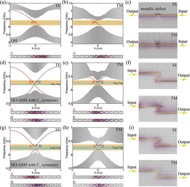
Figure 4. The projected band structure for two modes with (a) and (b) R1 = a/2.8 and R2 = a/2.6 (in HO-QSH phase) and R1 = R2 = a/3 (in QH phase), (d) and (e) two domains with C6v symmetry of R1 = R2 = a/2.6 (in HO-QSH phase) and R1 = R2 = a/3.7 (in CI phase), and (g) and (h) two domains with C3v symmetry of R1 = 2.8 and R2 = a/2.6 (in HO-QSH phase) and R1 = 3.4 and R2 = a/4 (in CI phase). The field profiles show the electric field Ez and magnetic field Hz of A and B points. The yellow regions denote the common frequency range for both TE and TM modes. The green regions denote the gap at edge state. (c), (f) and (i) TE and TM wave is confined to and guided by domain wall, exhibiting backscattering-immune propagation through defects.
Download figure:
Standard image High-resolution imageThe dual-polarization edge modes are also found in the domain wall by one part in the HO-QSH phase and the other CI phase. The QSH and CI phase can be in C6v symmetry (R1 = R2) or C3v symmetry (R1 ≠ R2). For the PC in C6v symmetry, the domain wall is constructed by the QSH phase with R1 = R2 = a/2.6, and the CI phase with R1 = R2 = a/3.7. Figures 4(d) and (e) plot the edge bands for the two modes, respectively. For each modes, two edge bands (marked by red and blue lines) are found in the bandgap, which corresponding to the pseudospin up and down, respectively. The figures show that the bandgaps for two modes have common frequency range, implying the edge modes are dual-polarization. We plot the mode field profiles for points A and B at the bottom of the panels. The electric field of the TE-mode and the magnetic field of the TM-mode concentrate at the domain wall. Also, we perform simulations of wave propagation along a Z-shaped domain wall. For the TE or the TM polarization, the incident wave passes around a Z-shaped corner and keeps moving rightwards, as illustrated in figure 4(f). The small gap in the edge bands is known as the result of symmetry broken at the domain wall. Figures 4(g)–(i) plot the edge states and the surface waves along the domain wall, where the two sides of PCs are with C3v symmetry; R1 = a/2.6 and R2 = a/2.8 for QSH phase and R1 = a/3.4 and R2 = a/4 for CI phase. The results are similar to figures 4(d)–(f). One difference of these edge bands is the gap width. The gap width of the PCs in C3v symmetry is larger than that of in C6v symmetry, which can be observed in figures 4(d) and (g) or 4(e) and (h). The increase of the gap width is 79 MHz for the TE-mode and 59 MHz for TM-mode.
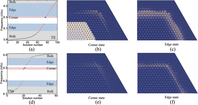
Recently, the QSH phase with gapped edge states have been revealed as HO-QSH phase with coexisting edge and corner states. A remarkable property of our HO-QSH phase is that it supports dual-polarization corner states. It is known that breaking the gapless edge states is a prerequisite for the corner state. For the PCs with C3v symmetry, the larger gap width is of great benefit to inducing corner states, and separates the corner state from bulk and edge states. To confirm the existence of corner state, we construct the PC with corners as shown insert of figure 5(b), which is implemented by the PC in the QSH phase at the center and the CI phase around. We numerically simulate the projected band structure of TE and TM mode, as shown in figure 5. We see corner states appear (blue dots) at about 6.298 GHz between the edge states (red dots) and the bulk bands (black dots) for the two polarizations. The field profile of the corner state for two polarizations is plotted in figures 5(b) and (e). The field closely localizes at the corner, which is different from the edge state where the field concentrates on the edges as shown in figures 5(c) and (f).
Figure 5. (a) and (d) The numerically calculated eigenfrequency for TE and TM polarizations, respectively. The bulk, edge and corner states are represented by gray, yellow and blue dots. The field distribution for (b) and (e) corner state, and (c) and (f) edge state.
Download figure:
Standard image High-resolution image
5. Conclusion
In conclusion, we have demonstrated the existence of dual-polarization topological phases in magnetic PCs. These phases include the QH phase, the HO-QSH phase and the CI phase. The topological nature of the phases is explored by the Wilson loop, Chern number, and the edge states of the phases. We show HO-QSH phases can present in the PCs with C3v symmetry, not limited in the C6v symmetry as previously reported. The reduction of the point group symmetry enlarges the gap in the edge states, which is of great benefit to inducing and separate the corner state from bulk and edge states. By continuously distorting the unit cell configuration, we display the phase transitions in the system, from the HO-QSH phase to the QH phase and then to the CI phase, which are dual-polarization. Our implementation provides a platform for studying dual-polarization topological phases and edge states, and paves the way for the applications such as dual-polarization devices for large-scale integrated photonic circuits.
Funding
This work is supported by National Natural Science Foundation of China (NSFC) (61771237). The authors acknowledge the assistance from the Project funded by Priority Academic Program Development of Jiangsu Higher Education Institutions and Jiangsu Provincial Key Laboratory of Advanced Manipulating Technique of Electromagnetic Waves.
Data availability statement
All data that support the findings of this study are included within the article (and any supplementary files).