


Abstract
There has been a growing interest in the phase of phonon, due to the theoretical prediction (Phys. Rev. Lett. 115.11 (2015)) and the experimental observation (Science 359.6379 (2018)) of chiral phonons, which have different phases in different components. While half-wave loss is a well-known concept in optics, in this work, a series of plateaus of quarters-wave loss are first found for the reflected phonon across an interface by using an atomic junction model. These plateaus can be understood by the S-matrix in the system with time-reversal symmetry. If a phonon wave propagates from a low acoustic-impedance material (or a low cutoff frequency material) to a higher one in the long-wave limit (or in the high frequency limit), a half-wave loss takes place for the reflected phonon; however, the plateau of half-wave loss for reflected phonon occurs in the whole frequency domain if phonon transfers to a material with a larger spring constant. Besides the half-wave loss, we also observe plateaus of quarter-wave (three-quarters-wave) loss in long wave limit when the two leads with identical acoustic impedance are coupled by a weak (strong) coupling in comparison with the optimum thermal coupling. The quarters-wave loss for phonons can be applied to chiral phonon manipulation and other phononics devices.
Export citation and abstract BibTeX RIS

Original content from this work may be used under the terms of the Creative Commons Attribution 3.0 licence. Any further distribution of this work must maintain attribution to the author(s) and the title of the work, journal citation and DOI.
1. Introduction
Recent years have witnessed a growing interest in revealing the properties of chiral phonons [1], which possess various phases in different components, since they were predicted in theory at the Brillouin-zone corners of an asymmetric two-dimensional hexagonal lattice without external magnetic fields [2]. And then via transient infrared spectroscopy, the chirality of phonons was experimentally observed in monolayer tungsten diselenide [3], which was lately shown entanglement with the corresponding single-photons emitted from quantum dots [4]. So far, the chiral phonons have been found theoretically not only in the honeycomb AB lattices mentioned above, but also in Kekué lattices [5], Weyl semimetals [6], graphene/hexagonal boron nitride heterostructure [7], center-stacked bilayer triangle lattices [8],  honeycomb superlattices [9], one-dimensional and bulk Ba3N-derived materials [10] and so on. Moreover, chiral phonons carry numerous potential importances to the research in many emerging field including valleytronics [11, 12], spin orbitronics [13], topological states [14] as well as polaritonics and their hybrids [15, 16]. Therefore, it makes great sense to study the phase of phonon.
As is known to all, in optics, the reflection coefficient of the normal incidence is dependent upon the indices of refraction of the two media. If the light travels in media from low refractive index to the high one, there will be a phase shift of π between the reflected wave and the normal incident wave [17]. Such phenomenon is referred as the half-wave loss [18], which has so far been applied to design quarter-wave antireflection coatings [19–21]. Since the solution of phonon wave is similar to that of the light wave [22], the natural question is whether we can find the half-wave loss, or even the quarters-wave loss for phonon reflected wave which may be contributed to not only adjusting the transmission coefficient but also tuning the phonon chirality. To study the phonon transport across interface, the one-dimensional atomic junction model is an efficient choice, which uncovers the phonon transport properties of the interface itself, including interfacial thermal conductance [23, 24], phonon interference effect [25], nonlinear interaction [26], interfacial thermal rectification [27], etc. In addition, for the sake of high accuracy, it is better to combine the 1D atomic junction model with the scattering boundary method owing to the full consideration of the atomic details in actual interfacial structures. The scattering boundary method was initially proposed by Lumpkin et al [28] to investigate the Kapitza conductance in a 1D lattice and it was by this way that Shafranjuk finally observed thermal energy to electricity conversion in the electrically polarized graphene stripes [29].
In this paper, applying the scattering boundary method, we study the reflected phonon wave phase change in one-dimensional atomic junction model and found a series of plateaus of quarters-wave loss through the interface, most of which company with the real transmitted wave and can be understood by the S-matrix. Our findings may allow us to control the transmission and the chiral phonon.
2. Model and method
To study the reflected phonon wave loss, we use a one-junction atomic model where two semi-infinite leads are coupled directly by a harmonic spring with constant strength k12, as shown in figure 1(a). Both of the leads are harmonic chains with spring constants kα and mass mα, α = 1, 2. Label each atom as  and the spring k12 is connected to the atoms 0 and 1. Assuming an incident wave
  transmitted from the left region to the right one, then it will be partially reflected and transmitted at the interface. From the equation of motion, we can obtain the dispersion relation for lead materials as
  [23]. Obviously, there are two roots for λ. In order to determine the forward moving traveling wave, one should replace ω with
  , and choose the one with
  of the two roots, which can be written as [30]
  . Finally, from the scattering boundary method, the real and imaginary parts of the reflected phonon wave can be expressed as


where

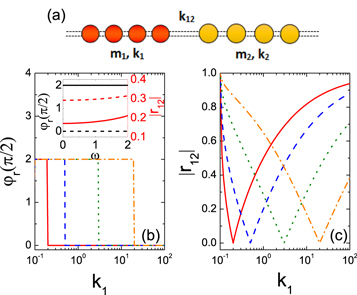
Figure 1. (a) Schematic of the one-dimensional atomic junction model. The left and the right parts are two semi-infinite harmonic chains with spring constants and mass as k1 and m1, and k2 and m2, respectively. Both of them are coupled directly by a harmonic spring with constant strength k12. (b) Reflected wave phase of interfacial materials with identical mass versus k1 for different interfacial couplings with k12 = k2. (c) Reflection coefficient of interfacial materials with identical mass versus k1 for different interfacial couplings with k12 = k2. For (b) and (c), ω = 1.0, m1 = m2 = 0.40; solid, dashed, dotted and dashed–dotted lines correspond to k2 = 0.20, 0.50, 3.00 and 20.0, respectively. Inset: reflected wave phase (left scale) and reflection coefficient (right scale) versus frequency ω; m1 = m2 = 0.40, k12 = k2 = 3.00; solid and dashed line correspond to k1 = 1.50 and k1 = 10.0.
Download figure:
Standard image High-resolution imageThus we can not only get the magnitude of reflected wave but also its phase φr. Here, we set  for consistency. Moreover, since the initial phase of the incident wave is 0, the reflected wave phase we calculated is equal to the phase shift between the reflected and the incident wave.
3. Results
3.1. Half-wave loss
At a given frequency ω = 1.0, figures 1(b) and (c) show the curves of the reflected wave phase and reflection coefficients as a function of k1 for different interfacial couplings in the case where the lead materials have identical mass and the interfacial coupling k12 equals the spring constant of one of the lead. At the point of k1 = k2, the reflected wave vanishes owing to the homogeneity of the atomic chain. If we change the spring constant of one lead material, then the interfacial mismatch will induce the phonon scattering and thus increase the reflection coefficient (see figure 1(c)), which also leads to a phase plateau of 0 or π (see figure 1(b)). In addition, the inset of figure 1(b) depicts the coefficient of the reflected wave increases as the frequency raises in the whole frequency domain, since the mismatch is more and more comparable to the decreasing wavelength; while the reflected wave phase is found to be frequency independent. Therefore, in any arbitrary frequency, if the interfacial structure has identical mass and its interfacial coupling is the same with the spring constant of one lead, there is half-wave loss for reflected phonon across the interface when phonons travel from a material with weak spring constants to that with strong ones.
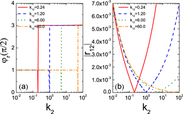
Especially, for the frequency limiting cases, i.e. in the long-wave limit or the high-frequency limit, the half-wave loss occurs independent of the mass and the interfacial coupling. Figure 2(a) shows the reflected wave phase as a function of spring constant of interfacial material k1 for diverse k2 in the long-wave limit. For the fixed  and k2, with the increase of k1, the reflected wave phase will first equal π and then reach its minimum after arriving at the point where the two leads have the same acoustic impedance Z1 = Z2, that is,
  . This means that when moving from a material with small impedance into that with relatively larger one, the phonon wave will have a phase shift of π for the reflected wave; otherwise, there will be no wave loss. The former phenomenon is quite interesting, since it is analogous to the light behavior when traveling in the media from low refractive index n1 to high refractive index n2 at normal incidence or the limits approaching normal incidence [31]. In figure 2(b), the curves of the reflection coefficients are completely symmetrical about
  , where the reflection coefficient values are minimum. Furthermore, whether the spring constant k1 increases or decreases, the reflection coefficient will increase due to the impedance mismatch. The inset of figure 2(a) shows that for the limit of long wavelength, both of the reflected wave phase and the reflection coefficient are interfacial coupling k12 independent since the far more larger wavelength greatly advances the phonon transport. In the high frequency limit, the fairly smaller wavelength hinders phonon transport thus give rise to the total reflection. Under this condition, if the cutoff frequency of the left semi-infinite lead ωC1 is lower than that of the right one ωC2, i.e.
  , the phase of the reflected wave is found to be equivalent to π. Here the maximum frequency is equal to the minimum of
  and
and  . This means that the plateau of half-wave loss with total reflection takes place in the high frequency limit which equals the cut-off frequency of the right lead.

Figure 2. Reflected wave phase (a) and reflection coefficient (b) versus spring constant of interfacial material, k1, in the long-wave limit. Here, m1 = 1.0, m2 = 2.0, k12 = 6.0; solid, dashed, dotted and dashed–dotted lines correspond to k2 = 0.15, 0.50, 5.00 and 50.0, respectively. Inset: reflected wave phase (left scale) and reflection coefficient (right scale) versus k12; m1 = 1.0, m2 = 2.0, k2 = 5.0; solid and dashed line correspond to k1 = 2.0 and 26.0.
Download figure:
Standard image High-resolution image3.2. Quarters-wave loss
In figure 2(a), it is obvious to notice that for k2 = 5.0 and 50.0 the reflected wave phase at the point of discontinuity is 3π/2 instead of zero. This means that for the lead materials with equal acoustic impedance, in the long-wave limit, the phonon wave still has tiny reflection. In fact, for the interfacial structures with equal impedance, the magnitude of r12 at low frequency limit is more rigidly zero at the point where

Here k12m denotes the interfacial coupling which makes the minimum reflection coefficient. As shown in figure 3, with the interfacial coupling k12 increasing, in the range between 0.1 and k12m, we can find a plateau of three-quarter-wave loss (see figure 3(a)), following with the reflection coefficient decreasing rapidly (see figure 3(b)); while out of this range, a plateau of φr = π/2 arises, as depicted in figure 3(a). At the same time, as shown in figure 3(b), the reflection coefficient first increases with the increase of k12 and then tends to a small constant,  . Note that if the interfacial coupling k12 is too weak, then all the phonon waves will be reflected since the wavelength is relatively much smaller. In addition, in the long-wave limit, if the two impedances become mismatched, the reflection coefficient will drastically increase and the phase value will abrupt change from π/2 or 3π/2 to π or 0, as shown in figure 2. Although the identical impedance condition in which quarters-wave loss occurs are difficult to realize for two different lead materials, in order to obtain quarters-wave loss one can construct a system with the same materials while varying the spring constant of the interfacial coupling k12, i.e. k1 = k2, m1 = m2 and
  .
.

Figure 3. Reflected wave phase (a) and reflection coefficient (b) for lead materials with equal acoustic impedance versus interfacial coupling k12 at low frequency ω = 0.001. Here, Z1 = Z2 = 2.0.
Download figure:
Standard image High-resolution imageWe further find other specific cases with quarters-wave loss between the reflected and incident phonons in 1D atomic junction model. As shown in figure 4(a), in the case where  and
and  , provided that the mass of the left region is large in comparison with that of the right one, i.e. m1 > m2, at the points of
  , the phonon will be fully transmitted. Then for the fixed k1, m1 and m2, between the two points, the coefficient of the reflected wave will first increase and then decrease with the increased ratio of k1/k2; while the corresponding phase remains π /2. When out of this range, the reflected wave phase will keep 3π/2 and with the ratio of k1/k2 farther away from the two points, the reflection coefficient
  will increase.
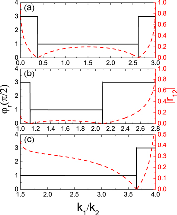
Figure 4. (a) Reflected wave phase (left scale) and reflection coefficient (right scale) versus k1/k2 under the condition of  and
and  (b)–(c) reflected wave phase (left scale) and reflection coefficient (right scale) versus k1/k2 for the case of
  and
and  . Here, (a) k1 = 2.50, m1 = 3.0, m2 = 2.0; (b)
  (c)
(c)  .
.
Download figure:
Standard image High-resolution imageBoth figures 4(b) and (c) show the other specific case, in which  and m1/m2 > μ0. Here, μ0 ≈ 0.8054 represents the value of m1/m2 which makes only one phase plateau of three-quarter-wave loss. For the fixed k1 − k2, m1 and m2, in the mass ratio m1/m2 range between μ0 and 1, as can be seen in figure 4(b), either the reflected wave phase and the reflection coefficient exhibit behavior similar to that in the first specific case, the only difference is that the inflection points of phase are given by
 ![${k}_{1}/{k}_{2}=\left(1+2\mu \right)/3+2/3\sqrt{{\left(1+2\mu \right)}^{2}-3}\cos \left[(\theta \pm \pi )/3\right]$](https://content.cld.iop.org/journals/1367-2630/21/9/093046/revision2/njpab4330ieqn28.gif) , where μ denotes the mass ratios of the left and right leads and
, where μ denotes the mass ratios of the left and right leads and ![$\theta =\arccos \left[\left(1-\mu \right)\left(8{\mu }^{2}+20\mu +17\right)/{\sqrt{4{\mu }^{2}+4\mu -2}}^{3}\right]$](https://content.cld.iop.org/journals/1367-2630/21/9/093046/revision2/njpab4330ieqn29.gif) . While for m1/m2 ≥ 1, as shown in figure 4(c), since the spring constants and the mass of the interfacial materials are positive numbers, the values of k1/k2 must be larger than m1/m2, leading to a single phase step at the point of
. While for m1/m2 ≥ 1, as shown in figure 4(c), since the spring constants and the mass of the interfacial materials are positive numbers, the values of k1/k2 must be larger than m1/m2, leading to a single phase step at the point of ![${k}_{1}/{k}_{2}=\left(1+2\mu \right)/3\,+\,2/3\sqrt{{\left(1+2\mu \right)}^{2}-3}\cos \left[(\theta -\pi )/3\right]$](https://content.cld.iop.org/journals/1367-2630/21/9/093046/revision2/njpab4330ieqn30.gif) .
.
Clearly, the two special conditions mentioned above are quite harsh. There may be other more stringent conditions where the phase plateaus of quarters-wave loss occur and thus will not be discussed.
4. Discussions
Certainly, the phase of phonon wave remains continuous in the whole frequency domain, as shown in the inset of figures 1(b) and 5. In order to further understand the essential reasons for the appearance of these quarters-wave loss plateaus, we define the S-matrix

which connects the amplitudes of the reflected and transmitted phonons to the incident ones [32]. Here  and
and  respectively denote the transmission amplitude and the reflection amplitude for an incoming wave from the right region. For the system with time-reversal symmetry, the scattering matrix S is unitary with additional symmetry, i.e.
  and S = ST, which are essential for energy conservation [33, 34]. Therefore, we obtain


This means that the transmitted wave is incident direction independent. Supposing that t is real, then equation (8) gives  . Thus, the total phase value among the reflections on one side of the interface and on the other one is always π. As depicted in figure 5, in the long wave limit, the transmission coefficient of phonon cross an interface has its maximum with φt = 0. At the same time, the reflected phonon wave exhibits half-wave loss and no-wave loss for mismatched acoustic impedance lead materials, as shown in figure 5(a); while for the leads with identical acoustic impedance, as can be seen in figure 5(c), there will be quarter-wave loss (or three-quarters wave loss) for phonon transmits to either side of the interface. We also calculate the phonon transmission with only mismatched spring constants of leads and found that it is a real number in the whole frequency domain companying with the no-wave loss for phonon reflected to one interface and half-wave loss for the reflection to the other one. While for other special cases, the underlying physics seems to be more complex and still need to be explored. Yet all the phase plateaus discussed above can be expressed analytically, as shown in appendix.

Figure 5. Reflected or transmitted phonon wave phase φr or φt (left scale) and corresponding coefficient (right scale) as a function of frequency ω. Here, for (a) and (b), k12 = 12.0; the solids line denotes m1 = 1.0, m2 = 3.0, k1 = 2.0, k2 = 5.0; the dashed line represents m1 = 3.0, m2 = 1.0, k1 = 5.0, k2 = 2.0. For (c) and (d), m1 = 1.0, m2 = 0.5, k1 = 2.0, k2 = 4.0, the solid and dashed line correspond to k12 = 1.0 and k12 = 6.0.
Download figure:
Standard image High-resolution imageThese plateaus of quarters-wave loss for the reflected phonon including the half-wave loss can be applied to tune the phonon chirality across an interface. Assuming a 3D lattice vibration in a 1D one-junction atomic chain, then the spring constants are 3 × 3 matrices and the force constant matrix can be made diagonal [35]. We define the direction from the left to the right as z axis and a circularly-polarized wave incident along this direction is assumed as  . Let the parameters
  (υ = x, y) and
  be spring constant of the α region and interfacial coupling in the υ direction, respectively. Since the propagation direction of the reflected wave is opposite to that of the incident wave, if the phase difference Δφ between the reflected wave phase along the x and y directions is ±π, then the phonon will keep its chirality; while if there is no phase difference, the phonon chirality will be reversed. Owing to the properties of plateaus of quarters-wave loss (except the condition of high frequency limit equivalent to the cutoff frequency of the left lead)—two of them with a phase difference of ±π can always be tuned by the spring constants of the interfacial materials or the interfacial coupling around the inflection point or points with total phonon transmission–one can select the x and y components of the spring constants both smaller or larger than the corresponding inflection point or points to change the phonon chirality; otherwise, the phonon remains unchanged. Especially, if the magnitude of the reflection coefficients along the x and y directions are the same, i.e.
  , the phonon will keep its polarization.
We can also use these plateaus to make conversion between linear-polarized phonon and circularly-polarized chiral phonon. Supposing a system with identical mass and the interfacial coupling equal to the spring constant of the right region along the x component, i.e.  and
and  , as discussed above, in any arbitrary frequency, as long as k1x is different from the spring constant in this direction, there will be half-wave loss or no-wave loss, as can be seen in figure 6. In addition, under the condition of m1 = m2, if
  and
and  , which is in fact the same with the case shown in figure 4, the quarters-wave loss will take place in the y direction, thus giving rise to a phase difference with the odd multiple of π/2 between x and y directions. This means that the anisotropic interface we constructed is able to work as a quarter-wave plate, which can convert a circularly-polarized phonon to a linear one. Furthermore, if
  , as denoted by points A and B in figure 6, the phonon can be tuned from linear polarization to circular polarization. Actually, the inflection points with full transmission discussed above, can be used to eliminate the reflection coefficient along a certain direction and finally obtain a linear-polarized phonon from a circularly-polarized incident phonon as well.

Figure 6. Reflected wave phase φr (left scale) and corresponding coefficient (right scale) versus k1/k2 for phonon transmitted across an anisotropic interface material. Assuming a 3D lattice vibration in a 1D one-junction atomic chain and a circularly-polarized phonon wave incident from the left region, if the interface is anisotropic, then a phase-change difference will take place for the two components perpendicular to the propagation direction. Here,  and
and  . Both point A and B satisfy
  .
.
Download figure:
Standard image High-resolution imageRecently, increasing efforts have been made to control the thermal transport [36–38]. Analogous to the technique of anti-reflective coating and reflective coating, we can apply the reversion between the half-wave loss and the no-wave loss for the reflected phonon to manipulate the thermal transport across an interface. Now we extend the junction to a center part with a size of NC. All of the three regions are coupled by the interfacial couplings k12 and k23. Then the phonon wave will be scattered by the second interface leading to the multiple reflections, thus the overall behavior of the reflected wave is a superposition of waves returning to the first boundary,

where  . In the following discussion, we only consider the first two waves, i.e. r12 and
  , since the magnitude of the reflected wave more than twice is trivial. Especially in the long-wave limit, the transmission wave from region α to β is
  with φt = 0 and the center region can works as a quarter-wave coating. Thus, for the case where the center part has the largest acoustic impedance, the half-wave loss only takes place when the phonon wave reflected from the first interface and thus give rise to constructive interference which in turn enhance the reflection coefficient. While for the impedance increasing material, when reflected from the second boundary, both the first two waves will exhibit half-wave loss. Therefore, in the long-wave limit, the phonon wave will travel half wavelength closer than the one reflected from the first boundary, leading to destructive interference, and finally promote the thermal transport across the interface which is certainly coincident with simulations [39–41]. Since the wavelength is frequency dependent, in other frequency domains, more factors must be considered, such as the thickness of the interfacial medium, so that the constructive or destructive interference between the two waves reflected to the left region occurs.
5. Conclusion
In summary, using the scattering boundary method, we study the phonon reflected wave phase for the interfacial thermal transport across a one-dimensional atomic junction model. In certain specific conditions, a series of plateaus of quarters-wave loss are found for the thermal transport across an interface. In the whole frequency domain, for the material structure with identical mass and the interfacial coupling equal to the spring constant of one region, if phonon transfers to a material with stronger spring constant, then there will be a phase plateau of half-wave loss. When in the long-wave limit, assuming that a phonon wave transmits to a material with large acoustic impedance, the phase shift between the reflected and the incident wave will be π; if not, there will be no wave loss. However, in this limit, for the leads with the same acoustic impedance, if the interfacial coupling is small in comparison with the harmonic mean of the spring constants of the two leads, there will be a phase shift of 3π/2 for the reflected wave; otherwise, a plateau of quarter-wave loss will take place. These plateaus mentioned above arise from the energy conservation in system with time-reversal symmetry companying with the real transmitted wave, which is in agreement with the S-matrix calculation. Thus, the sum of the reflected phonon wave phase between the phonon transport to one material and that to the other one remains to be π. Moreover, the phase plateau of half-wave loss also arises when phonon transports in materials from low cutoff frequency to the high one in the high frequency limit. We also obtained other special cases with rather strict conditions. These plateaus may have potential applications in the manipulation of chiral phonon and phonon transport through an interface.
Acknowledgments
We acknowledge support from NSFC (Grant No. 11890703).
: Appendix. Exact expressions of phonon reflected wave in complex number form in certain cases
For the limit of long wavelength, i.e. ω = 0+, we can obtain

This result is similar to the one obtained for the normal incident light wave in non-magnetic media, that is,  [31]. Here
  represents the wave impedance in the medium with refractive index nα , and
  is the wave impedance of free space which can be calculated from permeability μ0 and permittivity ε0 by
  .
.
For the interfacial structures with equal impedance, in the long wave limit, we get the coefficient of reflected wave as

Hence, in this condition, the magnitude of r12 is non-zero except at the point where  . In this case, with the spring constant of one lead material changing, the plateaus of quarters-wave loss can also be obtained, as shown in figure A1(a). With the increase of spring constant k2, at a low frequency ω = 0.001, for the interfacial materials with equal impedance, the plateaus of φr = π/2 and φr = 3π/2 appear before and after the point of
  , respectively; meanwhile, all the curves of reflection coefficients initially decrease and then increase at the same speed after reaching the minimum, as can be seen in figure A1(b).
Figure A1. Reflected wave phase (a) and reflection coefficient (b) for lead materials with equal acoustic impedance versus interfacial coupling k12 at low frequency ω = 0.001. Here,  .
.
Download figure:
Standard image High-resolution image
In the whole frequency domain, for the material structure with identical mass and the interfacial coupling equal to the spring constant of one lead, although the reflection coefficient curves shown in figure 1(c) are asymmetric about k1 = k2, yet it can be calculated by

Note that under the condition of m1 = m2, for the spring constant of the interfacial coupling k12 equal to that of the left lead k1, the effect of interfacial coupling on the reflected wave phase must be considered since it is now the reflection at the interface between k12 and the 0th mass rather than the 1th mass.