


Abstract
One challenge to synthetic biology is to design functional machines from natural building blocks, from individual amino acids up to larger motifs such as the coiled coil. Here we investigate a novel bipedal motor concept, the Bar-Hinge Motor (BHM), a peptide-based motor capable of executing directed motion via externally controlled conformational switching between a straight bar and a V-shaped hinged form. Incorporating ligand-regulated binding to a DNA track and periodic control of ligand supply makes the BHM an example of a 'clocked walker'. Here, we employ a coarse-grained computational model for the BHM to assess the feasibility of a proposed experimental realization, with conformational switching regulated through the photoisomerization of peptide-bound azobenzene molecules. The results of numerical simulations using the model show that the incorporation of this conformational switch is necessary for the BHM to execute directional, rather than random, motion on a one-dimensional track. The power-stroke-driven directed motion is seen in the model even under conditions that underestimate the level of control we expect to be able to produce in the experimental realisation, demonstrating that this type of design should be an excellent vehicle for exploring the physics behind protein motion. By investigating its force-dependent dynamics, we show that the BHM is capable of directional motion against an applied load, even in the more relaxed conformational switching regimes. Thus, BHM appears to be an excellent candidate for a motor design incorporating a power stroke, enabling us to explore the ability of switchable coiled-coil designs to deliver power strokes within synthetic biology.
Export citation and abstract BibTeX RIS

Original content from this work may be used under the terms of the Creative Commons Attribution 3.0 licence. Any further distribution of this work must maintain attribution to the author(s) and the title of the work, journal citation and DOI.
Introduction
The unquestionable importance of nanomotors in biology and nature's amazing ability to build an array of such machines from a set of molecular building blocks has inspired much study and many attempts at emulation [1]. Most of these efforts have involved the design and construction of synthetic nano-molecular machines using small molecules [1] and DNA [2, 3]. However, biological motors are predominantly protein-based. This has inspired efforts to design and synthesize directional molecular motors from protein-based components [4–7]. However, these protein-based concepts would achieve their motion only from diffusion, and lack a means to incorporate conformational change to stimulate directed motion.
Natural motors, such as kinesins and myosins, use conformational changes to vary their binding affinities during their motion cycles and to induce forward motion [8]. They exhibit an impressive range of properties such as autonomous directional motion in the thermal bath of the cell without direction-inducing external forces or gradients and the ability to carry cargoes of large relative sizes. Inspired by the operational principles of these motors, we propose the bar-hinge motor (BHM) concept. We have chosen a bipedal design for the BHM to emulate the dynamics of bipedal biological nanomotors such as kinesins and myosins. In contrast to our previous protein-based motor designs [4, 5], the BHM concept addresses directly the use of conformational change as a means of achieving stepping directionality.
In this paper we will first give a detailed description of the BHM concept. We then describe a proposed experimental realization of the BHM using a combination of components from our previous nanomotor concepts. These include coiled-coil domains for structurally near-rigid components [4], ligand-gated DNA-binding protein domains [4–6, 9], and a DNA track with corresponding binding sites [4, 5, 9]. To these we add a conformational switching moiety such as the photo-switchable molecule azobenzene [10]. Specifically we present plausible scenarios for the conformations of the BHM compatible with our current design knowledge, in order to base our simulation of the motor on realistic parameters. We then provide proof of concept by using Langevin dynamics simulations in conjunction with a coarse-grained model for the BHM. We first simulate the idealized case for the BHM where the system switches between two significantly different conformations. We then relax the conformational constraints provided by the hinge to and beyond those expected experimentally, to investigate how this affects the dynamics of the BHM.
The BHM concept
Biological stepping motors share key features: motor units (feet) that can bind to and detach from binding sites on a one-dimensional track and an ability to manipulate their free energy landscape to bias stepping in the forward direction. This is achieved by motors such as kinesin in an autonomous fashion, where changes in ligand occupancy of each foot from ATP to ADP to empty are driven by the ATPase activity of the foot and are controlled via ATP and ADP concentration in solution. While foot binding is controlled via ligand occupancy, kinesins and other stepping motors also couple these conformational changes between feet, so that efficient forward-directed motion is achieved. This latter property, often known as a power stroke, is achieved through the combination of ligand binding and allostery [11].
Here we investigate the motor properties of the BHM, a conceived synthetic bipedal protein complex that uses conformational switching in an externally controlled manner to produce directional motion. In contrast to biological motors that run autonomously, we achieve synchronization of stepping and conformational change via a clocked supply of ligand pulses and light-activated switching of conformational states. Synchronization of these external control parameters, coupled with appropriately stringent design of BHM geometries in the two switchable states, results in symmetry breaking and the desired directional motion along a one-dimensional track.
The principal design features of the BHM are two discrete track-binding domains (feet), FA and FB, that are mechanically coupled by rod-like 'legs' joined by a molecular hinge. Foot binding to specific sites along a one-dimensional track is controlled by environmental conditions, in our case via control of ligands la and lb in the buffer. Here it is assumed that la and lb must first bind to domains FA and FB, respectively, in order to enable them to bind to the track.
Under ideal conditions, the hinge component would give the BHM the ability to switch by external control between two conformations, a bar-like linear conformation, C1, and a V-shaped conformation, C2 (figure 1(a)). The track consists of an asymmetric periodic linear arrangement of target binding sites [-A-B-A-B-A-B-....] (figure 1(b)). Here, A and B are the target binding sites for FA and FB, respectively. The separation between A and B downstream, xAB, is twice the length, d, of the leg plus foot to accommodate the straight (bar) conformation, C1, of the BHM. The separation between B and A downstream, xBA, is sufficiently smaller than xAB to accommodate only the V-shaped conformation, C2, after conformational switching.
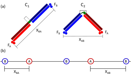
Figure 1. (a) The linear/bar and hinged/V conformations (C1 and C2, respectively) of the two-footed Bar-Hinge Motor (BHM). Two feet, FA and FB, are linked via rigid legs and a controllable hinge domain. In the ideal BHM, the hinge angle can be switched between two values, which enforces separations between the two feet commensurate with spacings between their binding sites on the track. (b) The track for the BHM, with binding sites for FA and FB. Track binding site separations xAB and xBA correspond to foot separations in conformations C1 and C2 respectively.
Download figure:
Standard image High-resolution imageProcessive motion is induced by supplying ligands la and lb externally and periodically via four successive ligand pulses such that at least one domain is bound to the track at all times. Directional motion can be induced by the synchronization of conformational switching with the ligand binding cycle in a manner described below. The ideal motility and processivity of the BHM concept is shown in figures 2(a)–(e). This is demonstrated under conditions in which the hinge angle is fixed in each conformation.
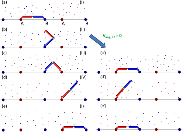
Figure 2. (a)–(e) show the expected progression of the BHM through one cycle of ligand pulses, starting at I (a) and progressing through to II (b), III (c), and IV (d) before returning to pulse I (e). For the non-idealised case of the BHM where the hinge can take a range of angles in one or both conformations, the system may pause, as shown in (c')–(e').
Download figure:
Standard image High-resolution imageThe BHM is initially bound in the bar configuration, C1, to the DNA track during ligand pulse I ([la, lb, C1]) with feet FA and FB bound to sites A and B respectively (figure 2(a)), where the notation [la, lb, C1] implies that both ligands are present in the buffer and that the hinge angle is ≈180°. During the subsequent ligand pulse [0, lb, C2] (pulse II), ligand la is removed from the buffer causing FA to detach from site A, and the motor conformation is switched to C2. FB remains bound to site B (figure 2(b)). The motor executes diffusional motion in the V-shaped conformation C2 during this pulse. During the next pulse [la, lb, C2] (pulse III), ligand la is reintroduced into the buffer. The motor continues to execute diffusional motion in C2 until FA eventually binds to the downstream site A as dictated by the track polarity, provided that the duration of the ligand pulse is long enough (figure 2(c)). During the following ligand pulse [la, 0, C1] (pulse IV), ligand lb is removed from the buffer causing FB to detach from site B, and the motor conformation is switched to C1. FA remains bound to the second A site (figure 2(d)). The motor executes diffusional motion in the bar configuration, C1, during this pulse. This is the last ligand pulse of the cycle and it is followed by ligand pulse I which initiates the next ligand pulse cycle during which FB binds to its appropriate downstream binding site. The centre of mass of the BHM will now have advanced a distance (xAB + xBA) (figure 2(e)). The BHM is designed in this manner to coordinate conformational switching, powered by the input of light, and stepwise rectified diffusion, powered by externally controlled changes in chemical potential, so as to induce directional and processive motion along the track. It should also be noted that by using the opposite synchronisation of the light with the ligand pulses the direction of the motor could be deliberately reversed, which may be useful for future applications.
The components for this BHM concepts are all experimentally realizable. To reiterate, the design requirements are:
- 1.Two orthogonally regulated track-binding domains (feet).
- 2.A scaffold linking the feet into one motor unit, containing an integrated hinge domain compatible with two distinct angular conformations.
- 3.A method of switching the hinge from one state to the other in a controlled, repeatable manner.
- 4.A method of making the steps directional along a suitable track.
In the following paragraphs, we outline our proposed components for each of these requirements.
- 1.Two orthogonally regulated track-binding domains (feet). As for other protein-based motor designs [4, 5], we propose to use ligand-gated repressor proteins. As examples, TrpR and DtxR are repressor proteins which bind to specific DNA sequences in the presence of a specific ligand (tryptophan for TrpR [12], iron and some other divalent metals such as cobalt for DtxR [13, 14]). The distinct ligand and sequence requirements for foot binding using these two repressors means that binding of FA and FB to a DNA track can be independently controlled.
- 2.A scaffold linking the feet into one motor unit, containing an integrated hinge domain compatible with two distinct angular conformations. In keeping with our aim of using amino acids wherever possible, we have designed a peptide hub connecting the two feet with a switchable central region. Our initial design consists of two coiled-coil domains flanking a central flexible peptide region. This is achieved by three peptide sequences: a long peptide with a flexible central region, and two shorter partner peptides, each of which binds specifically to one end of the long peptide to form coiled-coil dimers. These two dimeric coiled coils give the 'legs' of the hub stable, rigid structures. As in the Tumbleweed design [4, 15], the coiled-coil peptides should assemble in an orthogonal fashion, i.e. each alpha-helix should associate with the desired partner. This will enable the motors to self-assemble, resulting in the formation of bipedal motors with two different 'feet'. The flexible central peptide region is used for control of angular geometry: with an additional addressable group (described in point 3 below), it can function as the hinge.In an ideal system, one state would be fixed at 180°, and the other at a smaller fixed angle. It is, however, difficult to achieve a second fixed angle in such a system. Our aim instead is to produce one conformation in which the whole peptide hub will be helical, rigid, and bar-like, and a second conformation in which a flexible centre will allow a V shape (along with other conformations between a bar, θ = 180°, and a hairpin, θ = 0°). We plan to design a long peptide sequence such that the helicity of the central region is sufficiently weak that it samples other conformations regularly, and can be locked out of a straight, read-through helical conformation by an external change in environment.
- 3.A method of switching the hinge from one state to the other in a controlled, repeatable manner. Many mechanisms have been used for conformational control of peptide-based switches, including changes in pH [16, 17], temperature [18], metal binding [19–22], and through attachment of a moiety that is consequently conformationally adjusted [23]. In the BHM system, the use of pH, temperature or metal ions to induce conformational changes is undesirable: protein denaturation may occur at high temperatures; additional ions may interfere with the existing ligand cycling system; and pH may (a) be difficult to adjust with the requirements already needed for the solvent system and (b) affect the folding or stability of the protein feet. The use of electromagnetic radiation would, therefore, be a suitable candidate for the induction of switching, mediated through a peptide-bound azobenzene moiety. The use of light-sensitive domains is not unknown in nature; many organisms (plants, fungi, bacteria) have been found to contain LOV domains, proteins with a flavin cofactor, sensitive to blue light [24]. Azobenzene represents a small molecule equivalent to these domains that is a useful size for the proposed BHM and which has been used in DNA motors to produce conformational switching [25, 26].Azobenzene is a compound that undergoes cis-trans isomerization on irradiation with different wavelengths of light. Irradiation using wavelengths of the order of 360 nm has been used for switching from the trans to cis conformation [23, 27, 28]. The two azobenzene isomers have different end-to-end lengths, and have been used as a means of locking peptides into different conformations [10, 23, 27, 28]. Azobenzene isomerizes very quickly, on the scale of picoseconds [10], and hence in peptide hybrid systems undergoing conformational change, the rate limiting step will be the peptide rearrangement. Earlier studies indicate that azobenzene coupled to peptides in alpha-helical systems are able to switch the peptide secondary structure between a disordered structure and alpha helix [23]. Switching within a coiled-coil context is a more difficult undertaking however, with preliminary work indicating that azobenzene cannot induce a coiled coil to switch to a random coil (Cano-Marques, unpublished). We therefore propose the use of a helical-random coil region in the hinge region, forming a break in between the two more cooperatively folded coiled-coil regions. The expected BHM peptide conformations (with helical and random coil conformations for the cis and trans azobenzene-encompassed regions) are shown in figures 3(a) and (b), as produced using molecular modelling software [29].
- 4.A method of making the steps directional along a suitable track. The use of alternating separations between A and B binding sites of feet FA and FB was described in the concept section above as a means to enforce directionality (assuming correlated conformational switching and ligand supplies to control foot binding state). The use of the repressor proteins means that a DNA-based track can be realized, containing repeated A and B protein-binding DNA recognition sites, interspaced by non-recognition site stretches of DNA. This track can be synthesized from DNA using the same methods as for the Tumbleweed motor track [9]. Clocked control of the ligand environment can be achieved through microfluidics [6, 30] making it possible to synchronize the light switching of the azobenzene with the flow of specific ligand states through a computerized system that controls both simultaneously.
Figure 3(c) shows a rendering of the proposed structure for the BHM construct and its track. For this idealised BHM, both the bar conformation, C1, and the V-shaped conformation, C2, have fixed hinge angles. It is, however, to be expected that in an experimental realisation of the BHM, both C1 and C2 conformations would be more flexible, i.e. both conformations would be able to access a range of angles. The question then arises as to how much the constraints on the angle for the two conformations can be relaxed while still retaining motor directionality. Addressing this question is a focus of the simulations in this study.
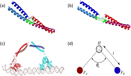
Figure 3. Cartoon representations of the BHM showing the (a) cis and (b) trans conformations of the azobenzene moiety, and its expected effect on the helical-random coil hinge region of the peptide system. (a) represents the 'bar' conformation C1, due to its extended helical region. (b) Represents the 'hinge' or 'V' conformation C2, in which the central region adopts a random coil structure. (c) Rendering of the proposed structure of the experimentally realised BHM, displaying the coiled-coil regions, DNA-binding protein domains and DNA track. (d) Coarse-grained model of the BHM as used in simulations consisting of 3 spheres (hinge H, foot A and foot B) bound by two rigid harmonic bonds of length l.
Download figure:
Standard image High-resolution imageMinimal model and Langevin simulations
We investigated the behaviour of the BHM by simulating its motion using a coarse-grained minimal model in conjunction with three-dimensional overdamped Langevin dynamics [5, 6]. Figure 3(d) shows the coarse-grained model used in our simulations. The BHM is represented by a freely jointed linear molecule composed of two rigid harmonic bonds connecting three spheres. The rigid bonds represent the legs (coiled coils) of the BHM. The two spheres at the terminals of the motor represent the track-binding modules (feet), FA and FB. The third sphere represents the hinge module, which connects the two stiff bonds. We use the indices j = 1...3 to designate the two BHM feet and the hinge: 1 ≡ FA, 2 ≡ the hinge module and 3 ≡ FB (figure 3(d)). Let  be the change in the value of the ith coordinate (i = 1,2,3) of the jth module over an incremental time, Δt, at time t. The overdamped Langevin equation can then be written as follows:

Here kB is Boltzmann's constant, T is the absolute temperature,  is the ith component of the sum of an internal conservative force,
  and an external load force, FL, on the hinge module (j = 2) at time t. FL is always taken to be parallel to the track. γ is the drag coefficient for each monomer and is given by the Stokes–Einstein equation in terms of the radius, rs, of the monomeric sphere and the viscosity, η, of the buffer: γ = 6πηrs. The last term in equation (1) models thermal noise. ζi(j)(t) is a random number taken from a Gaussian distribution with zero mean where

 acts on each monomer and is the negative gradient of a potential given by WH + WSB + WLJ + Wang. Here WH is a harmonic potential which determines the length of the rigid bonds of the BHM:

VH is the strength of the harmonic potential, r is the distance between the end point monomers of the bond at any given time and l is the equilibrium bond length (see figure 3(d)). WSB is the specific binding potential present at all binding sites on the track. The track is taken to lie along the x-axis and the specific binding potential for a foot of type j to its specific recognition sequence is given by:

VSB is the strength of the specific binding interaction, db is its effective range and rj is the distance between foot j and the nearest corresponding binding site (recognition sequence A or B) on the track. To model the case where a ligand is absent from the buffer, the specific binding potential is turned off by making WSB(rj) = 0. WLJ is the excluded volume between the two feet and is simulated by a repulsive Lennard–Jones interaction in terms of the actual distance, ρ, and σ is the diameter of the each of the two spherical monomers representing the feet of the BHM (see figure 3(d):

We used two different methods for conformational switching in the simulations. The first method uses a bending potential given by:

Here θ is the hinge angle between the two rigid legs of the dimer, θ0 is the equilibrium hinge angle between the rigid legs when both feet are bound to the track in either the hinge (subscript h) or bar (subscript b) conformation and Vang is the strength of the bending potential. Simulation results show that the shape of the bending potential in equation (6), the magnitude of Vang and the thermal fluctuations affect the range of hinge angles explored.
The second method involves the use of available data for the range of allowed hinge angles either from experiment or molecular dynamics simulations. We use this method to elicit the minimal requirement for conformational switching to result in directional motion.
The numerical parameters used in the simulations are motivated by realistic values for an experimental implementation using repressor proteins and a DNA track. For most simulations, the BHM is started in the bar conformation, C1 (figure 2(a)). Changes in ligand concentrations are modelled by turning the corresponding binding potentials on or off at ligand pulse changes. Binding of a motor foot occurs if it happens to diffuse within a distance db of an active binding site. The value of VSB has been chosen large enough to ensure that, once bound, a monomer does not unbind until the corresponding specific binding potential is turned off. The value of the ligand pulse time, τLP, used in the simulations is 1.47 ms. This value is chosen to be much larger than the first passage times for binding in pulses I and III (see figures 2(a), (e) and (c), respectively) and therefore ensures processivity. The values for τLP accessible in experiments is expected to be much greater than 1 ms [6, 30], but this does not have a significant qualitative effect on the simulation results.
Simulation results
The specific parameters used in the simulations are given in table 1. In particular, the track distances are: xAB = 12.7 nm, xBA = 7.62 nm, the length of each rod-like peptide = 6.35 nm and the hinge angle, θ0, when foot A and foot B are both bound to the track, is therefore ∼180° for the bar conformation C1 and ∼74° for the V conformation C2.
Table 1. Model parameters.
| Parameter | Symbol | Value |
|---|---|---|
| Long lattice constant in track | xAB | 12.7 nm |
| Short lattice constant in track | xBA | 7.62 nm |
| Bond length of leg (coiled-coil) | l | 6.35 nm |
| Drag coefficient of each track-binding module sphere | γ | 3.76 × 10⁻¹¹ kg s−1 |
| Effective range of specific binding | db | 1.5 nm |
| Interaction strength of specific binding potential | VSB | 4.1 nN nm |
| Interaction strength of harmonic potential | VH | 32.8 pN nm−1 |
| Interaction strength of Lennard–Jones potential | 4∈ | 16.4 pN nm |
| Diameter of 'foot' spheres FA and FB | σ | 4 nm |
| Langevin time step | Δt | 0.46 ps |
| Thermal energy | kBT | 4.1 pN nm |
Case A: Ideal BHM concept
We first investigated the dynamics of the 'ideal' BHM, which we refer to as BHM0. This motor has strong angular potentials (Vang-h = Vang-b = 1000 kBT) to enforce the distinct geometry of the C1 and C2 conformations (figure 4(a)). The stepping behaviour of the simulated BHM0 shows that the motion is both directional and processive with no pauses or reversals (figure 4(b)). This is expected in the case of tight conformational switching as demonstrated in figures 2(a)–(e), i.e. the BHM0 switches directly from the bar conformation, C1, to the V conformation, C2, as the ligand pulse is changed from I to II and the reverse from pulse III to pulse IV.
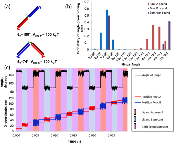
Figure 4. The ideal BHM concept (BHM0). (a) Cartoon indicating the hinge angle and potential used in Case A. (b) The x-coordinate (stepping curve) of both feet (lower curve) and the hinge angle, θ, (upper curve) as functions of time for zero load force. The vertical lines divide the figure into time ordered ligand pulses starting with ligand pulse I on the left hand side. Here the periodic ligand pulse sequence is (I–II–III–IV–I–II....). The stepping curve shows the spatial fluctuations of BHM0 during each pulse. (c) The distribution of the hinge angles generated from several clocked ligand pulse sequences.
Download figure:
Standard image High-resolution imageThe tight conformational switching of BHM0 is confirmed by examining the hinge angle dynamics (figure 4(b)). This graph shows that the BHM0 is in the bar conformation with hinge angle θ0 ∼ 180° during ligand pulse I when both feet are bound to the track. The small fluctuations in angle are due to the large but finite bending energy (Vang-h = Vang-b = 1000 kBT) and to the range of the track binding potential (db=1.5 nm). The BHM0 is next switched to the V conformation with θ0 ∼ 74° in ligand pulse II with only foot B bound to the track; the distribution in hinge angles shown in the graph results from thermal fluctuations related to the form of bending potential of equation (6). The BHM0 remains in the V conformation, C2, but with much smaller angular variation when both feet are bound in ligand pulse III. It is then switched to the bar conformation, C1, in ligand pulse IV where only FA is bound. Note that the distributions of the hinge angle in ligand pulses II and IV do not overlap and that there is a distinct gap between them. This can be seen clearly in figure 4(c), which gives the overall distribution of hinge angles for an entire cycle of ligand pulses.
The absence of overlap of the two hinge angle distributions ensures that the BHM0 exhibits progressive and directional motion with no pauses or reversals. This is the case when the value of Vang in equation (6) is chosen to be much greater than kBT for both conformations. Furthermore, an external load force is expected to have no effect on the velocity of the BHM0 until it is strong enough to prevent forward binding during ligand pulses I (figures 2(a) and (e)) and III (figure 2(c)), in which case the BHM0 detaches from the track.
Decreasing the bending energy in the ideal BHM concept
As stated above, it may be challenging from an experimental standpoint to attain such rigidly fixed hinge angles. Hence, we next investigated how relaxing this constraint affected directional motion (figure 5(a)). The effect of decreasing the bending energy on the motion of the BHM0 is given in figure 5(b). The data show that at Vang-h = Vang-b = 20 kBT perfect stepping still occurs. However, pauses and reversals occur in the motion of the BHM for Vang-h = Vang-b = 6 kBT . When the potential is further decreased, figure 5(b) shows that more pauses and reversals are induced into the motion, causing a decrease in motor velocity until the motion becomes a random walk for Vang-h = Vang-b = 0. Clearly, we can no longer regard the motor as representing the ideal BHM concept in this case. As the bending potential is decreased, thermal fluctuations increasingly allow the BHM to bend away from the bar conformation (C1) during ligand pulse IV (figure 2(d)). This opens the possibility of the BHM making a reverse step in the following ligand pulse I (figure 2(e)), resulting in the rearward binding of FB and the motor being in the bound C2 configuration as in figure 2(c). However, during the next ligand pulses II and III, FA would simply unbind and rebind in the same location. This is seen in figure 5(b): the angular potential is still strong enough to prevent rearward binding in ligand pulse III, with foot A then rebinding to its earlier binding site resulting in a second pause. After this complete cycle of ligand pulses, it may pause again, or else exit this pause and resume its forward motion.

Figure 5. Modification of BHM0 by choosing a range of values for Vang-h = Vang-b. (a) Cartoon showing the parameters used in the simulation. (b) The stepping curve for foot A for several values of Vang-h = Vang-b at zero load force. When Vang-h = Vang-b = 20 kBT, the stepping curve is identical to that found in figure 4(a) i.e. the BHM is fully directional. (c) The stepping curves for foot A for several values of the load force when Vang-h = Vang-b = 2 kBT. The motor is easily reversed by an applied load. (d) The force–velocity curve calculated from average trajectories when Vang-h = Vang-b = 2 kBT. (e) The stepping curves for both feet at full reversal (Vang-h = Vang-b = 2 kBT, F = 2.3 pN). (f) The distribution of the hinge angle generated using clocked pulse sequences when the motor is fully reversed (Vang-h = Vang-b = 2 kBT, F = 2.3 pN).
Download figure:
Standard image High-resolution imageWe examined the motion of the BHM for Vang-h = Vang-b = 2 kBT when a load force, FL, is applied to the hinge module. Figure 5(c) indicates that the directionality is lost in this case is between 0.3 and 0.5 pN. This figure also shows that the direction of motion is reversed and that the rate of reversal increases at the expense of pauses or forward steps as FL increases. Further, the velocity of the BHM decreases with increasing load force until the motion of BHM is fully reversed for FL ∼ 2.3 pN.
As this motor is capable of running both forwards and backwards, it becomes meaningful to identify a stall force. This can be seen in figure 5(d) where the velocity passes through zero at a force of around 0.4–0.5 pN. The motor is no longer a simple Brownian ratchet but able to convert the energy provided externally that provokes the conformational change, into work done against the load force [31]. As such the motor is exhibiting behaviour consistent with a power stroke. Although there is energy put directly into the system via the absorption of a photon locking in conformational change, this energy cannot be directly responsible for the power stroke of the motor. This is because there is no direct coupling between the conformational change and the direction of movement of the motor's centre of mass. Instead, the power stroke behaviour is rooted in the energy barrier to backward steps produced by the bending potential.
The velocity as a function of load force can be predicted using this model by estimating the energy barrier for forward stepping to be the work done moving the centre of mass forward by the minimal distance required to achieve binding (9.66 nm). The barrier for backward stepping can also be estimated by calculating the energy of the minimal bend required to achieve backward binding against the bending potential (the hinge configuration bending to 134° and the bar configuration bending to 85.5°). The energy barriers for each type of step can be converted into estimated stepping probabilities and hence a predicted velocity as a function of the load force. Figure 5(d) shows that this model fits reasonable well to the simulation data. Although the BHM shares many features with the biological motor kinesin including the selection of the stepping foot, the bias in forward binding caused by a conformational switch and its ability to do work via its directional motion, it compares poorly on performance, with kinesin having a stall force an order of magnitude higher for a similar step length [32, 33].
The stepping diagram and the angular distribution for full reversal are shown in figures 5(e) and (f) respectively, and it can be seen from figure 5(f) that the BHM samples all angles from 30° to 180° when only one foot is bound. The mechanism for full reversal is due to the load force, which takes over from conformational switching when the angular potential is strongly affected by thermal fluctuations. This effect has also been demonstrated to occur for the Inchworm motor concept described in [6]. In an experimental scenario the binding potential would need to be strong enough to prevent detachment of the BHM by the load force for full reversal to be achieved.
Case B: BHM concept for bar with completely flexible hinge conformations
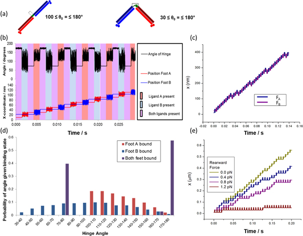
Drawing motivation from experimental design realities, we see that the bar conformation C1 (figure 3(a)) is expected to be more constrained than the hinge conformation C2 (figure 3(b)). This is because the bar conformation is designed, due to the dimensions of the cis conformation of azobenzene, (i) to have helical structure throughout its peptide components [10, 23, 27, 28] and (ii) to have more closely pinned coiled-coil regions than those in the hinge conformation (figure 3(b)). Thus, we examined the case when Vang-b is kept much greater than kBT, i.e. during ligand pulses IV (figure 2(d) and I (figures 2(a) and (e)), while Vang-h = 0 in ligand pulses II (figure 2(b)) and III (figures 2(c) and (c')) where the hinge angle can then take on all values from 30° to 180° during these pulses. Angles below 30° are prevented by the Lennard Jones (excluded volume) interaction between FA and FB (equation (5)). We name this motor concept BHM1 (figure 6(a)).

Figure 6. The BMH1 concept for which Vang-b = 100 kBT. (a) Cartoon showing the parameters used in the simulation. (b) The stepping curve for both feet shows that the velocity of BHM1 is decreased by the occurrence of pauses. (c) Comparison of the stepping curves and velocities for BHM0 (Vang-h = Vang-b =100 kBT; purple) and BHM1 (blue) at zero load force. (d) The overlapping distributions of the hinge angle generated using several clocked ligand pulse sequences for BHM1 at zero load force. (e) The stepping curves for foot A for several values of load force. More pauses are induced in the motion of BHM1 as the load force is increased.
Download figure:
Standard image High-resolution imageBecause of its flexible hinge, during pulse III, the BHM1 is able to bind either in the forward direction, by adopting the V conformation C2, thus promoting directional motion (figures 2(c) and (d)), or back in the same location by adopting a bar-like conformation, C1, in which case motion of the BHM1 is paused (figure 2(c')). When a pause occurs, BHM1 becomes out of sync with the ligand pulse sequence and will undergo a second pause (figures 2(d') and (e')). As in the previous example, the pauses are expected here also to occur in pairs, and several pairs of pauses may follow one another before directional motion resumes.
The dynamics of BHM1 are shown in figure 6. As predicted, BHM1 exhibits both double and quadruple pauses, yet its overall motion is directional and processive (figure 6(b)). The motor does not run backwards because of the high energetic cost to bend the bar conformation into a hinge angle for a backwards step. Figure 6(c) indicates that the velocity of BHM1 is lower than that of BHM0, by about 30%, for our parameter values. The distribution of BHM1 hinge angles is shown in figure 6(d). In contrast to the BHM0 (figure 4(b)), BHM1 exhibits overlapping angular distributions of the one-foot-bound states. As expected, the motor is able to select any hinge angle from 30° to 180° when only FB is bound.
Figure 6(c) presents the stepping diagrams when a load force acts on the hinge and shows that more pauses are induced by increasing the load force, leading to an eventual near suppression of the directional motion. The behaviour is similar to that of the Vang-h = Vang-b = 1000 kBT instance of BHM0 in that the motor cannot run backwards and a stall force cannot therefore be calculated.
A more detailed analysis of the effect of the load force on BHM1 was performed. First, we investigated how the load force affected the probability of taking a forward step versus pausing. We found that forward stepping probability decreased monotonically with load force, while pausing increased in a compensatory manner (figure 7(a)). No detachment was observed in the force regime measured. These probabilities enabled us to calculate the velocity of BHM1 as a function of the load force (figure 7(b)), where we observed the velocity to decrease monotonically with applied force.

Figure 7. Probability analysis for BMH1 motion. (a) Probabilities of a forward step (Pf) and a pause (Pp) in ligand pulse III as a function of load force. (b) The velocity, vM, of the motor as a function of load force using the expression vM = v0Pf/(Pf + Pp) where v0 is the velocity of BMH0 at zero load force (see figure 6(c)). (c) Probabilities of a forward step and a pause in ligand pulse III for zero load force when the hinge angle of the bound conformation C2 is varied from 40° to 180°, achieved by altering the track spacing. (d) Probabilities in ligand pulse III of a forward step and a pause for zero load force as Vang-h is increased from zero (BHM1) to 8 kBT. At this value, Pf ∼ 1 and Pp ∼ 0, implying that the BHM0 case has been reached.
Download figure:
Standard image High-resolution imageNext, we wished to investigate how the dynamics depended on the hinge angle in the V conformation C2 of BHM1 when both feet were bound. To study this, we varied the spacing of the binding sites on the track. In all of the simulations presented thus far, the track distances were given by xAB = 12.7 nm and xBA = 7.62 nm. The latter value, together with the leg length of 6.35 nm, led to a hinge angle, θ0 (C2) of 74° for the bound C2 conformation. In BHM1, hinge angles allowed within the free C2 conformation range from 30° to 180°. Thus, we altered the xBA spacing on the track to provide hinge angles in the bound C2 conformation within this range, and repeated the analysis of stepping probability, now as a function of hinge angle. Figure 7(c) shows that the probability of a forward step decreases and the pause probability therefore increases as θ0 (C2) is increased. This implies that the velocity of BHM1 decreases with increasing hinge angle until both probabilities are equal.
We can also proceed from BHM1 to our initial BHM0 results by reintroducing the bending energy Vang-h for the C2 conformation in ligand pulses II and III (figures 2(b) and (c), respectively). Figure 7(d) shows that the BHM becomes fully directional with no pauses (i.e. BHM0 is recovered) for Vang-h ≥ 8 kBT for the parameter values given in table 1.
Case C: How much further can the fixed angle conformations be relaxed while still retaining motor directionality?
We have already shown above that the BHM concept with the hinge angle fixed for the bar conformation (C1) only (BHM1) retains motor directionality. We now demonstrate that the fixed angle conformations can be relaxed even further. We have already studied an idealised motor, and one where the motor C2 can sample 30°–180°. The experimentally-based justification for this was provided in the previous subsection. However, thermal fluctuations will still influence the system, and hence even the bar conformation is likely to undergo sampling of at least a small range of angles about 180°. We have therefore also modelled the system where the hinge angle in the bar conformation C1 can vary from 100° to 180°, while allowing the hinge angle in the V conformation C2 also to have a great deal of flexibility, varying from 30° to 180°.
We will refer to this version as BHM2 (figure 8(a)).
Figure 8. The BHM2 concept. (a) Cartoon indicating parameters used for BHM2 (b) The x-coordinate of both feet (lower curve) and the hinge angle, θ, (upper curve) as functions of time for zero load force. The vertical lines divide the figure into time ordered ligand pulses starting with ligand pulse I on the left hand side. (c) The stepping curve for both feet at zero load force shows that the velocity of BHM2 is decreased by the occurrence of pauses (compare with the upper curve of figure 1(a)). (d) The distribution of the hinge angle generated during several clocked ligand pulse sequences. (e) The stepping curves for foot A for several values of the load force.
Download figure:
Standard image High-resolution image
During ligand pulse 1, BHM2 is again in the bar conformation, C1, with hinge angle θ0b ∼ 180° when both feet are bound to the track. In ligand pulse II, only foot B is bound to the track, and θ is allowed to vary from 30° to 180° for ligand pulses II and III. BHM2 can thus bind during ligand pulse III either in the angular conformation, C2, in the forward direction, thereby promoting directional motion, or in the bar conformation, C1, in which case motion of BHM2 is paused. In ligand pulse IV, only foot A is bound to the track and θ is only allowed to vary from 100° to 180° in ligand pulses IV and I. Under these conditions BHM2 can only bind in the bar conformation, C1, in the following ligand pulse I, since the hinge angle of the angular conformation C2 (θ0 ∼ 74°) is forbidden.
The motion of BHM2 shown in figures 8(b)–(d) is, therefore, qualitatively the same as that of the BMH1 shown in figures 6(b) and (d). Figure 8(e) gives the stepping diagrams for BHM2 when a load force acts on the hinge and is, again, qualitatively the same as that of the BHM1 shown in figure 6(e). The distribution of the hinge angles generated using several clocked ligand pulse sequences for BHM2 at zero load force is shown in figure 8(d). Figure 8(b) also shows the hinge angle, θ, as a function of time for zero load force for BHM2.
The BHM2 appears to perform slightly less well than the BHM1, however it is extremely promising to see that we can maintain motor directionality while trading off an increase in the overlap of the angular distributions for motor performance. These simulation results give strong evidence that the proposed experimental realisation of this motor may indeed be functional.
Conclusion
We have presented a novel conceptual motor design, known as the BHM, which specifically aims to explore the role of conformational switching in motor function. The motor is bipedal and steps along a DNA track due to external control of the ligands required for the feet to bind. When an external conformation switch is synchronized with stepping, the motor transitions from stepping randomly along the track to moving directionally. A key strength of this proposed system is that loss of fidelity of the conformational change only reduces the extent of directional motion as opposed to causing the motor to dissociate from the track and become lost. This will have tremendous benefits within an experimental system.
We have performed coarse-grained simulations on a variety of examples of this motor concept spanning from idealised constructs to those with properties that represent likely achievable physical molecules. In all cases we have shown that the motor can undergo processive stepping and do work against an externally applied drag force. We demonstrate a trade-off between the control of the conformations in either switched state and the velocity and stall force of the motor.
The BHM has been demonstrated to be an excellent candidate system in for the exploration of the crucial roles of conformational switching within protein motion. It offers an opportunity to explore the design of both power strokes and, in the future, synchronization of stepping with switching, which are key steps toward delivering the first autonomously walking designed protein motor.
Acknowledgments
LSRS: Funding from EPSRC Doctoral Prize EP/M507854/1. MJZ: Funding from Westgrid and Compute Canada for the use of computing facilities. NRF: Funding from a Natural Sciences and Engineering Research Council of Canada (NSERC) Discovery Grant RGPIN-2015-05545. HL Swedish Research Council Project no. 2015-03824. PMGC: Funding from Australian Research Council Discovery Project Grant DP170103153.