


Abstract
Neutral beam injection is one of the most important methods of plasma heating in thermonuclear fusion experiments, allowing the attainment of fusion conditions as well as driving the plasma current. Neutral beams are generally produced by electrostatically accelerating ions, which are neutralised before injection into the magnetised plasma. At the particle energy required for the most advanced thermonuclear devices and particularly for ITER, neutralisation of positive ions is very inefficient so that negative ions are used. The present paper is devoted to the description of the phenomena occurring when a high-power multi-ampere negative ion beam travels from the beam source towards the plasma. Simulation of the trajectory of the beam and of its features requires various numerical codes, which must take into account all relevant phenomena. The leitmotiv is represented by the interaction of the beam with the background gas. The main outcome is the partial neutralisation of the beam particles, but ionisation of the background gas also occurs, with several physical and technological consequences. Diagnostic methods capable of investigating the beam properties and of assessing the relevance of the various phenomena will be discussed. Examples will be given regarding the measurements collected in the small flexible NIO1 source and regarding the expected results of the prototype of the neutral beam injectors for ITER. The tight connection between measurements and simulations in view of the operation of the beam is highlighted.

Original content from this work may be used under the terms of the Creative Commons Attribution 3.0 licence. Any further distribution of this work must maintain attribution to the author(s) and the title of the work, journal citation and DOI.
1. Introduction
The history of negative ion beams is already several decades long and their field of use is still growing, including several scientific and technological applications, from sources for accelerators and spallation neutron sources, to nuclear fusion and industrial applications [1]. Particularly progress is recently driven by the use of negative light-ion beams for heating and current drive of thermonuclear fusion plasmas. Such beams are required to have huge energy and current as well as low divergence and high uniformity. The present paper is intended as a summary of the phenomena, like beam neutralisation and compensation of beam space charge, affecting the beam properties during the drift of the beam after the acceleration phase. Particular attention will be devoted to the case of high power beams made of negative ions, of the type to be employed in neutral beam injectors (NBI) for plasma heating and current drive in ITER. Applications and exemplifications will regard the prototype of the ITER heating NBI. The next section will deal with the physics of beam neutralisation and transport, whereas section 3 will be devoted to the experimental characterisation of the beam and of the aforementioned phenomena.
The realisation of the ITER Heating NBI (1 MeV particle energy, 40 A accelerated current, 3600 s pulse duration), clearly entails a large step forward in terms of power and energy output with respect to all NBIs operating in the existing tokamaks. Consequently, PRIMA, the ITER Neutral Beam Test Facility [2], was set up to constitute a test-bed, where the solutions to all the issues related to the achievement of full performances in the heating NBI system for ITER are going to be addressed and optimised, particularly regarding critical aspects like density and uniformity of the extracted negative ion current, high voltage holding and heat loads on the components [3]. Megavolt ITER Injector Concept Advancement (MITICA) is the full-scale prototype of the ITER NBIs [4]; it includes an RF-driven plasma source for the production of negative ions and should operate at a pressure as low as 0.3 Pa in hydrogen or deuterium gasses. The negative ions are produced on the surface of the grid (Plasma Grid, PG) that closes the plasma region; their production is enhanced thanks to a thin caesium layer continuously deposited over the PG by evaporation. Negative ions are extracted through the 1280 apertures in the PG by application of a suitable positive voltage to the extraction grid (EG), located just downstream of the PG. The RF plasma source operates at an applied electric potential of about −1 MV. Five additional acceleration grids (AG1, AG2, AG3, AG4, GG), at intermediate electric potential increasing by 200 kV steps, are located downstream with respect to the EG, thus constituting a 5-stage electrostatic accelerator. The resulting negative ion beam at 1 MeV, after passing through a gas cell neutraliser and an electrostatic residual ion dump (RID), should produce a ∼17 MW neutral beam focused onto a target calorimeter for a duration up to 3600 s.
Source for production of ions of deuterium extracted from RF plasma (SPIDER) [5] is a full-size test-bed of the ion source and extractor for the ITER heating NBI and it will operate at an acceleration voltage of 100 kV at the same current and pulse duration. A CAD view of SPIDER is shown in figure 3.
In the vicinity of PRIMA, a small and versatile negative ion source, dubbed negative ion optimisation (NIO1) [6], is under operation with the aim of producing a 130 mA negative hydrogen current, divided into 3 × 3 apertures and accelerated to 60 kV; unlike SPIDER and MITICA, NIO1 is operated continuously [7].
2. Physics of beam neutralisation and transport
The topic underlying the present paper is the interaction between the propagating beam and the background gas; on the one hand this results in the creation of electrons as well as of fast and slow ions; on the other hand partial neutralisation of the beam occurs, allowing neutral beam injection into magnetised plasmas. Moreover, if the beam were propagating in vacuum, after the ions are extracted from the source and electrostatically accelerated, it would spread under the effect of its own space charge: the presence of ions of the opposite charge opposes this diverging effect. Finally, the neutral gas and the charged particles are heated by the beam and deposit their energy over the surfaces exposed to the beam. These effects and their consequences are the main subject of the present paper and will be described in this section, starting from a short description of the beam formation processes.
2.1. Beam formation
Negative ions can be produced by dissociative attachment of electrons to ro-vibrationally excited hydrogen/deuterium molecules or by the interaction between a hydrogen or deuterium plasma and low work function surfaces facing the plasma, the latter presently being the most effective way although it presents some drawbacks in view of its use for fusion applications. The formation of negative ions is described in dedicated reviews like [1]. Once the negative ions are emitted from the surface they have to reach the apertures in the plasma facing grid and must be extracted as described for instance in [8]; as collisions with electrons having energy >2 eV can destroy the negative ions, in the vicinity of the plasma-facing electrode a magnetic field (magnetic filter) is usually applied parallel to the electrode to reduce the amount and the temperature of electrons in this so-called extraction region [9]. The extraction of negative ions, along with the acceleration, has long-ranging consequences on the beam features, particularly in terms of beam optics, which describes the tendency of the beam to concentrate or to spread during its propagation. In order to guarantee a good energy transfer from the beam to the tokamak plasma, tight requirements apply to the final beam optics, so that this is one of the most important aspects for the performance of a NBI; hence several analytical and numerical codes are used for beam optics simulation; some of them are commercial codes, whereas some others are developed ad hoc.
The design of a negative-ion-based NBI for plasma heating aims at minimising the divergence of each single beamlet as well as of the whole negative ion beam, and, simultaneously, at avoiding high concentrations of heat loads on the accelerator grids. This is normally obtained by means of suitable magnetic and electrostatic field configurations so as to guarantee an efficient dumping of electrons.
Generally speaking, two approaches can be applied in the simulations: a local and a global approach; figure 1 is used for exemplification.

Figure 1. View of a vertical array of beamlets in MITICA apertures. The electrostatic deflection due to the beamlets having charge of the same time can be seen (topmost beamlet); details of the EG, together with the system of magnets (CESM and ADCM) devoted to dump the co-extracted electrons while minimally affecting the negative ions (see section 2.3); the PG aperture exhibits the so-called Pierce angle on the downstream side; on the upstream side the meniscus is sketched in red.
Download figure:
Standard image High-resolution imageIn the case of the local (or single-beamlet) approach, only a single beamlet is considered, whose optics is evaluated in terms of beam average divergence at the exit of the accelerator and clearance around the beamlet. To this purpose, a 2D code, capable of computing the electric field inside the accelerator by integration of the Poisson's equation with cylindrical geometry conditions, is generally used. A possible choice is the SLACCAD code, a modified version of the SLAC Electron Trajectory Programme [10], adapted to include ions, a free plasma boundary and a stripping loss module [11]. This code was benchmarked against data from negative ion experiments, in CEA [12], JAEA [13, 14] and IPP [15], with a generally good agreement. The main output of this analysis is usually the geometry of the grid apertures giving the best overall performance. As the run time of the calculations is quite short, a large number of cases can be studied and compared, and also sensitivity analyses over a large range of variables can be carried out.
In the case of the global (or multi-beamlet) approach, several beamlets are considered and also the detailed geometry of the grids, including possible double curvatures and additional field-shaping electrodes (called 'kerbs'). Full 3D finite elements codes must be used in this case, like the commercial codes OPERA [16] or COMSOL [17] or the beam acceleration codes described in [18, 19]. Although less precise than 2D codes like SLACCAD in the evaluation of the single beamlet divergence, 3D codes permit the estimation of overall effects of the whole beam, including edge effects. This fully 3D approach allows to describe intrinsically three-dimensional effects that cannot be studied by 2D codes, such as the repulsion between the beamlets, the effect of the detailed shape of the grids and the combined influence of electric and magnetic fields. For example, an important output of these simulations is the identification of the optimal shape and location of the kerbs, on the downstream side of the grids, so as to modify the electric field and to compensate for the repulsion between the beamlets and to guarantee the overall aiming of the entire beam [20].
As already mentioned, numerical simulations result in the shape and distance of the accelerating grids; at particle energies below or around 100 keV acceleration can be performed in one single gap, although the triode structure is preferable to attain a better final optics [21], the central electrode being the EG. At higher energies multi-stage accelerators are preferred due to their better voltage holding capabilities and to the lower amount and energy of electrons [22, 23].
Indeed in a negative ion accelerator, a certain amount of electrons is unavoidably extracted together with the negative ions, as they have the same charge [21]. The ratio between these co-extracted electrons and the negative ions can vary between 0.5 and over 10, depending on caesium deposition inside the plasma source, EG temperature, magnetic filter field, negative ion species (deuterium or hydrogen) etc [24]. Due to the large heating power associated to the co-extracted electrons, operation at full performances is only permissible if the electron-to-ion current ratio is of the order of one or less. In order to reach a good overall efficiency of the accelerator and to reduce heat loads on the grids, this large quantity of electrons (some tens of Amperes all across the extraction area) must be stopped in the first part of the accelerator, before they gain too much energy. For this reason, strong and localised magnetic fields are produced by a set of permanent magnets located inside the EG, which force nearly all co-extracted electrons to impinge on the EG itself [9]; to reduce the power deposited onto the EG, the first voltage step is kept as low as 5–15 kV [22].
In multi-stage accelerators, electrons generated inside the accelerator due to the phenomena described in section 2.4 (stripping of negative ions and ionisation of the background gas) are most conveniently deflected onto the grids of the next acceleration stages by the magnetic field produced by suitable permanent magnets embedded in the accelerator grids [25]. In MITICA a combination of a long-range and short-range magnetic fields was designed and optimised so as to force most of the electrons to impinge on the grid located just downstream in the same gap where they are generated; the deflection of the negative ions is minimised by a suitable alternation of the polarity of the magnets (figure 1 [4]).
Also other particles can impinge on the grids: negative ions having poor optics, mainly the ones composing the so-called beam halo [26]; neutrals; positive ions. For instance, the power loads from halo particles are particularly high on the last three grids of the MITICA accelerator, where they can represent half of the total heat load, the other half being due to the stripped electrons. The main code used to estimate the heat loads generated by these electrons on the accelerator grids is EAMCC [27]. This is a 3D Monte Carlo code tracking the particles in prescribed electric and magnetic fields, also taking into account the secondary particles (electrons, neutrals and positive ions) generated by surface or volume reactions. The electric field to be used in the EAMCC code can be calculated either by 2D or 3D codes; also the background gas density, playing an important role in volume reactions (stripping and charge exchange), has to be numerically estimated (see section 2.6). The target pressure for the ion source of the heating neutral beams (HNB) for ITER is 0.3 Pa; the definition is given in terms of the filling pressure, namely the equilibrium pressure in the absence of plasma. The flow is then kept constant while the discharge is started. The gas temperature in the source during the discharge must be considered [28] to estimate the operational gas density just before the PG, but also to calculate the temperature decrease along the accelerator which can be computed by accommodating the gas particle energy at the electrode walls [29]. In the MITICA accelerator, only a minor fraction of the gas flows frontally, due to the wide lateral openings between the support structures (more than 50% of the gas exits through the first lateral gap). The gas density is high in the first few centimetres out of the plasma source and determines the maximum loss of beam ions in that region; furthermore, the gas exiting the plasma source is a mixture of atomic and molecular hydrogen, the former offering a larger cross section for stripping of negative ions.
Neutral atoms generated in the accelerator carry the largest fraction of the stray power. Nonetheless, due to their low energy reflection coefficient, the disposal of their power does not represent a critical issue, as their impact point can be easily estimated.
2.2. Space charge effects
The space charge effects in a negative ion source depend, in the first place, on the applied voltage and electrode design and on the uniformity of the ion current density jH− and on the ratio, Rj, between the emitted electron current density, je, and jH−, and, in the second place, on the strength of the deflecting magnetic field By. Hydrogen is considered in the following. A simple estimate of electron-to-ion density ratio in the extraction region is Rn = fRRj(me/mH)1/2, where fR is the recirculation factor of electrons (slightly greater than 1 when the average electron Larmor radius rL is larger than the extraction gap, g, and greater than 2 for stronger By), and me and mH are electron and ion masses. For Rj ≪ 10 the electron space charge is then a second order correction, and the ion emission current density jH at the cathode is saturated at the upper limit given by a local Child–Langmuir law (which assumes a vanishingly small emission speed):

with V(d) = ϕ(d) – ϕc the voltage sampled at a small distance d from the meniscus (the thin transitional region between the plasma, exhibiting small electric fields and quasi-neutrality, and the beam region, with huge electric fields and essentially a single charge species; this region acts as the cathode and emits particles) and qH the signed ion charge. An estimate of extraction voltage (including electron effects, with uniform current density) is

where fV is a dimensionless factor greater than one, necessary to obtain a concave meniscus and thus a converging ion beam in the extraction gap (typically fV = 1.6 [30]); this convergence helps particles to better pass into the EG apertures and balances the EG lens effect (known as anode lens effect [31]). In other words the mentioned fV values include a safety margin for good extraction and the case fV ≅ 1 (parallel beam at cathode) is unpractical, since large beam expansion is not desired. Another well-known condition for focussing electrode design is that the angle between beam envelope and focussing electrode be about (3π/8) at the extraction (so-called Pierce angle [31], see figure 1). When Rj ≪ 1, equation (2) is more easily expressed in terms of beamlet perveance Pb ≡ Ib/VE3/2 and Child perveance limit Pch as follows

where Ao is the extraction hole area and Ib ≅ Ao jH is the beamlet current. The limit on the extracted current density turns into the necessity of multi-aperture beams when large currents are required like for NBI injectors for fusion applications [22]; moreover, the negative ion surface generation mechanism is only effective in the vicinity (few mm) of the EG surface, again limiting the maximum aperture radius.
This compensation of space charge effects by an adequate extraction voltage and electrode design gives a beam with a smoothly changing envelope radius r(z), where z is the extraction axis: as r'(z) ≪ 1, a paraxial beam envelope equation is obtained [32]:

where V(z) is the acceleration voltage, which can be defined as V(z) = (½)m with vR the speed of the reference particle which travels on axis; moreover AEMI is a term proportional to the square of the beam transverse emittance, εt (that is the area in the position-momentum phase space occupied by the beam). The paraxial approximation is possibly prone to large errors near the extraction region z ≪ g; here z = 0 is the extraction aperture plane and zn 0 the meniscus and axis intersection. For z ≪ g the relation between r(z) and V(z) and electrode shapes is given by self-consistent space charge equilibria [31, 33], which thus determine the starting conditions for r(z) and V(z) in equation (4).


Note also that, as a first approximation, AEMI may be neglected with respect to the space charge term for NBIs dedicated to fusion plasma heating, which are characterised by cold ions, having a low spread in the phase space and raising the space charge upon keeping together, and by large currents, again contributing to the space charge.
The accelerating field V'(z) may change from one gap to another and it reduces inside a grid aperture, so that ∣V''(z)∣ exhibits peaks before and after each grid. Equation (4) accounts for the anode lens effect by the V'' term, and for the acceleration beam compression by the V'(z) term, and shows the importance of Pb(z) = Ib/V3/2(z) in driving the beam expansion. In the idealised case of an infinitely long drift tube z > zd with no current compensation [34], this equation reduces to 9πrr'' = Pb(zd)/ko, easily solved with the coordinate transformation


The use of equation (4) for optimising the extraction electrode design was pointed out [36].
2.3. Beam deflection
The beam expansion under the influence of space charge, described by the beam envelope equation (4), is compensated for by carefully shaping the electrode apertures along the accelerator. An aperture having different electric fields on its sides, in fact, works like an electrostatic lens for the particles (rays) crossing it. In particular, a divergent lens is formed at the grid entrance, and a convergent lens at its exit. Using the so called thin lens approximation, the effect of both lenses can be combined to evaluate the resultant focal length as [37]:

where V(z1) is the potential at the electrode position, and Ed and Eu the electric field values downstream and upstream of the electrode respectively. The condition Ed > Eu gives a net converging lens, that can be used to counteract the beam expansion induced by the space charge. When the beam crosses any electrostatic lens with a certain offset δr with respect to the nominal axis, the lens induces a deflection φ in the beam that can be evaluated as φ = δr/f. The stronger the lens (i.e. the difference Ed – Eu), the higher the deflection induced in the beam particles, so that the most demanding alignment requirements regard the EG, whose lens must harness the high current density of the low energy beam, and the grounded electrode, which has Ed = 0 and hence a strong diverging effect. On the other hand this effect can be exploited to effectively steer the individual beams of multi-beamlet accelerators towards a common focal point [22, 38, 39]. Many causes could determine misalignments between the beam and the aperture axes; some of them have mechanical origin, like the misalignments between apertures during grid realisation and installation [40] or the grid deformation induced by thermal loads. The first can be minimised by careful alignment of the electrodes, whereas the second can be addressed using dedicated thermal analyses [4, 5]. Other sources of beam misalignment have a physical origin, such as the beam displacement due to the space charge repulsion by surrounding beamlets or under the influence of the magnets installed in the EG in order to deflect the co-extracted electrons (called co-extracted electrons suppression magnets, CESM). The former can be minimised by centring the electrode apertures with respect to the expected beam position and/or using passive suitably shaped structures (the kerbs) to increase the transversal inward component of the electric field between the electrodes; the latter needs more sophisticated solutions. The deflection angle induced by the combined effect of CESM and EG lens steering, in fact, can be large (several mrad) and depends on beam energy, magnet size and distance between CESM and plasma.
In existing NBIs the straight ion trajectories are recovered by adding a dedicated electrode at the exit of the EG [41, 42], whose aperture axis displacement is tuned so as to compensate for the CESM-induced deflection, according to equation (7). As already mentioned, in the case of SPIDER, MITICA and NIO1 a different approach was adopted, based on tailoring the magnetic field profile along the accelerator so as to compensate for the unwanted beam deflection, which itself has a magnetic origin. This can be attained by placing additional magnets in the successive electrode [5] or in the EG itself together with the CESM [43]. In the latter case the magnets (called ADCM, for alternate deflection compensation magnets) are magnetised in the perpendicular direction with respect to CESM (figure 1). As to the profiles of the vertical component of the magnetic field, By(z), the By produced by the CESM changes sign from the z < zm region to the z > zm region, where z = zm is the middle plane of the magnet array, whereas the By generated by the ADCM has a single peak and has the scope of increasing the CESM magnetic field peak in the upstream side of the EG, while decreasing the downstream peak. The idea is based on the configuration developed by Halbach [44].
A similar magnetic compensation of the ion deflection is implemented in SPIDER [5]; in this case the compensating magnets are located in the GG, which is also provided with a ferromagnetic layer on the downstream side. In SPIDER the more common electrostatic compensation is adopted for some beamlet groups; others are left without any compensation in order to assess the relative effectiveness of the various methods.
The minimisation of the beam deflection induced by CESM can be demonstrated (similarly to the envelope equation (4)) on theoretical grounds. It is assumed that all electrode apertures have a common radius Rm, which is approximately satisfied by many designs (NIO1 has respectively, 7.6 mm, 7 mm and 7 mm diameter apertures in PG, EG and post-acceleration grid, so Rm = 3.5 mm; MITICA has apertures of diameters: 14 mm for PG, 13 mm for EG, 14 mm for the following two acceleration grids, 16 mm for the last three acceleration grids; so Rm ≅ 7 mm). The average, X(z), of the particle displacements, x, when crossing a constant z plane satisfies [45, 46]:

where em = ∣q∣/mH, and u1(z) contains the additional deflections due to electrons or to the other ion beamlets, of course strongly attenuated by distance and electrode shielding. Note that u1(z) = 0 exactly inside drift tubes, if present, and that a term proportional to is included, due to beam attraction towards image charges on the drift tube (the direct repulsion between ions of the same beamlet, proportional Ib/πr2, has no effect on the average beam displacement). Major deflection causes are the magnetic field (By term) and the beam optics (V''(z) term).

The initial conditions for X(z) at z = 0 may depend on plasma dynamics; as a first working assumption, X(0) = 0 and X'(0) = 0 can be used, that is the ion beam leaves the plasma centred, is deflected by By reaching the EG aperture with some displacement, so suffering the EG anode lens deflection; final deflection is the combined effect of By and V(z) growth. The line integral of By for CESM vanishes at infinity, while ADCM has a finite Ia(+∞) = JA value. Convenient approximations (for a large array) are

where ko = π/Ly with the array period Ly and IA, JA and IC are constants, given elsewhere [46] or easily numerically computed from magnet sizes.
The numerical solutions of equation (8) were extensively compared to beam tracking simulations and to analytical solutions of equation (8), while neglecting u1 and with a fair agreement. These analyses have shown the possibility of zero (within one or few millirads) final deflection αf = atan X'(zf) for several electrode voltage settings and currents, for some ratio of ADCM and CESM size (or equivalently for some ratio JA/(IA + IC)). It seems possible to use the same magnets when Ib changes, provided VE is changed so as to keep the perveance constant and the other voltages are proportionally scaled [45]. Stability with respect to the postulated meniscus position, zn, is also fair [46]; on the contrary, changing the VE voltage alone (while keeping total acceleration V(zf) constant) affects the deflection (for fixed magnets).

Experimental results in a 30 kV accelerator [47] have confirmed the reduction of the ion deflection with suitable ADCM, although the deflection tends to be larger than in simulations. Other, more detailed experiments are planned. These results motivate to consider more in detail: (1) effects of the u1 term, such as beamlet–beamlet interaction; (2) effect of plasma current uniformity [48]; (3) influence of the starting conditions X(0) and X'(0), that is the average ion beam deflection at plasma meniscus. In recent simulations [49], in fact, it was pointed out that the CESM magnets also affect the trajectories of negative hydrogen ions from the caesiated surfaces, where they are created, to the meniscus (extraction) area, and the resultant negative ion distribution available at the meniscus is drastically unbalanced in the transversal plane. Numerical modelling of beam acceleration based on such an assumption of unbalanced current density showed an enhanced beamlet deflection [50] during the acceleration. The latter can be responsible for the discrepancy between measured and numerically estimated beamlet deflections, as highlighted in [48]. It should be noted that the electron emission condition is strongly related to By and to collisions. Some recent solutions of integro-differential models show that the electron flow at extraction has a large velocity component parallel to the meniscus (up to twice the thermal speed) at least for some collision models [51, 52]. This fosters the investigation of the asymmetry of the electron space charge with effects on meniscus shape and on initial ion deflection.
2.4. Beam gas interaction
For proton beams the most significant mechanism of interaction between beam particles and matter is the transfer of energy from a beam particle to a shell electron via Coulomb interaction. If the target is gaseous, excitation and emission of light or ionisation of the gas particle occurs. In the case of negative ion beams the beam particle itself exhibits the same behaviour: the charge state of beam particles evolves along the drift region due to interaction with the background, constituted by a partially ionised gas. In the following the two effects, on the beam charge and on the target gas, are treated separately.
The beam fractions, expressed as particle fluxes of negative (Γ−), neutral (Γ0), and positive (Γ+) particles, evolve as described by the following set of equations:
where are the cross sections for collisions against the kth target species of a beam particle having initial charge state i and final charge state j. The target species k can be molecular hydrogen, atomic hydrogen, plasma ions or electrons, and collisions are treated as simple two-body collisions; depends on the relative velocity and is commonly given as a function of the energy per atomic mass unit. In high power negative ion beams, the terminology is inherited from proton beams. The first of equation (10) includes single and double electron detachment from the negative ion, also called single and double stripping. Neutralisation channels from negative and positive ions are included in the second equation, mostly due to single electron detachment and charge exchange respectively, and reionisation is the loss term. In the third equation the proton flux is increased by double stripping and reionisation, while it is decreased via the neutralisation channel. The fourth equation introduces a flux of fast electrons with energy Ee = (me/mi)Eb stripped form the ion beam: loss by scattering is indicated in the last term on the right-hand side, where the momentum transfer cross section represents the complete loss of parallel velocity. Electrons are considered as fast only if their energy is enough to ionise hydrogen molecules H2. Cross-sections are obtained from [53].


Beam induced ionisation of the gas target, and generation of a secondary plasma, are the second effect. Slow molecular ions and plasma electrons are produced by ionisation; additionally, fast electrons Γse are generated by stripping, and molecular ions are created by charge exchange. All these processes contribute to the source terms Ge and Gi of plasma electrons and of ions respectively. The loss term L is the same for thermal electrons and molecular ions, being a function of the recombination per unit volume (it may include dissociative neutralisation and all processes yielding neutrals) and of radial density gradients via ambipolar diffusion Da. The source terms Gi, Ge, and the loss terms Li,e are expressed as charges produced per unit volume and unit time and can be calculated as functions of the beam fractions and the cross sections (which are obtained from [53, 54]):
It is worth pointing out that the loss terms depend on the plasma density and its gradient, but the source terms depend on the beam current. The ionisation process yielding molecular ions dominates over any other process generating atomic ions [55], and dissociation by stripped or plasma electrons is not effective enough; therefore the plasma is mostly composed of molecular ions and electrons.
In the case of a 100 keV and 1 MeV negative hydrogen ion beams, figure 2 exemplifies how the precursor beams evolve through an H2 gas target, and how the rate of slow ions and electrons is consequently different. At 100 keV (figure 2(a)), the peak neutral flux is higher than at 1 MeV (figure 2(b)) and requires a lower target thickness. Furthermore, at the lower energy there is an equilibrium between charge exchange and reionisation processes, which saturates at Γ0/Γ+ ∼ 0.6; at the higher energy, the asymptotical condition, reachable only at large target thickness, corresponds to a sole proton beam. The cumulative rate coefficients Gi, Ge are three times larger for the lower energy beam (figure 2(c)); the contribution to Gi from charge exchange somewhat balances the other asymmetric contribution from stripped electrons to Ge (the beam is basically 'pumping' electrons from molecular gas into fast stripped electrons). Charge exchange is negligible at the higher energy (figure 2(d)) whereas ionisation by stripped electrons can represent a consistent fraction of plasma production. Generally speaking, an unbalanced generation of plasma particles (Ge/Gi ≠ 1) can be expected in low energy beams.

Figure 2. Evolution of fast particles for negative hydrogen ion beam at 100 keV (a) and 1 MeV (b); generation of plasma particles by 100 keV beam (c) and 1 MeV beam (d).
Download figure:
Standard image High-resolution imageThe beam particles undergo collisions with the background gas, resulting in stripping (also double stripping) of the beam particles and ionisation of the neutral gas; however, energy is also transmitted to the gas, resulting in background gas heating. This topic is under investigation for the ITER HNB since several years, also because it might result in a reduced effectiveness of the gas neutraliser caused by heating of the gas. According to present understanding, this possible reduction of the capabilities of the neutraliser seems to be ruled out for ITER HNBs [56]. However the gas is indeed heated: using the stopping power from NIST [57] for protons on hydrogen target, 700 MeV cm2 g−1 at 1 MeV, gives 25 eV m−1 for an average gas pressure of 0.15 Pa, equivalent to 250 W per neutraliser channel in MITICA. The contribution of stripped electrons at 473 eV has to be added, resulting in 4700 W for each of the four neutraliser channels for a fully stripped beam. Electrons at this energy have an average mean free path for inelastic collisions of 2.7 m; therefore a non-negligible fraction of their energy can be assumed to be transferred to the gas molecules and then to the neutraliser panels.
2.5. Secondary plasma formation and space charge compensation
As mentioned in section 2.2, the equation ruling the evolution of the beam envelope along the beam path, in the absence of electric fields (outside of the accelerator), is [32]

where fe is the fraction of space charge compensation (see just after equation (13)) and the beam envelope r(z) was defined in equation (4); K is proportional to the beam perveance, generalised to account for space charge compensation, and is written as

with the introduction of fe to take into account the possibility that the beam space charge is reduced, as will be discussed soon. Both terms on the right-hand side of equation (12) contribute to the variation of the beam width. The first term corresponds to the beam expansion under the effect of its own space charge; the second term is related to the natural tendency of a beam with non-zero emittance to become wider and wider because some beam particles travel at an angle with respect to the average beam direction. Manipulation of the equation leads to the following implicit form of the solution [32]:

where the geometrical emittance ε was introduced. The relative value of the terms on the right-hand side of equation (12) depends on the beam space charge: a critical perveance exists above which space charge forces dominate and a zero emittance treatment can be adopted [58]; as already mentioned, this is the relevant case for the present paper, which deals with high-intensity negative ion beams.
As described in section 2.3, the interaction between the negative beam and the background gas results in the production of positive ions and electrons. Particles having the same charge polarity as the beam particles tend to be expelled from the beam, whereas particles with opposite charge polarity tend to be trapped in the beam potential well. Together with the travelling negative ions, all these particles create a plasma, which partially compensates for the beam space charge. Consequently the beam divergence decreases and the beam can propagate for long distances (otherwise under the effect of its own space charge the beam would blow up radially [32]; even if the radial particle motion were hindered by a strong magnetic field, the beam current could grow only up to a value defined by the building up of a potential barrier in the beam [21]). Inside the accelerator, lenses can cope with the beam space charge; outside of the accelerator this plasma is required [59]. The characteristics of such a plasma are determined by a competition between the generation phenomena described in the previous sections and the loss of particles, peeled off at the edge of the beam [21]. After steady state conditions are attained, for each type of particles the generation and loss rate by the plasma are the same; the radial transport of particles might also be ambipolar. Concerning positive ion beams drifting through a background gas, perfect compensation of the beam space charge is never attained, as mobility is larger for electrons than for positive ions, and in the centre of the beam a residual positive potential is found of the order of the electron temperature [9], a situation resembling usual plasmas [21]. Further rise of the background gas pressure would increase beam losses due to charge transfer collisions and would lead to larger beam divergence due to elastic collisions.
On the other hand negative ion beams can be both under- and over-compensated, essentially depending on the background gas pressure (in addition to beam parameters), as found during extensive investigations performed by Soviet researchers and summarised in [60]. This condition can be described [61] upon defining nb the beam particle density, vb the beam particle speed, ng the background gas particle density, and using the following weighed cross-sections for production of slow ions and electrons:
In steady state, positive ions and electrons are created inside the beam and lost radially at the edge of the beam; the equilibrium condition can be respectively written as:

The plasma hypothesis can be assumed: ne + nb = ni. Hence a critical value exists for the background gas density:

The critical density occurs when the accumulation of ions in the beam equates the amount of negative charges; this corresponds to the approximation performed in equation (17), resulting from the different velocities of electrons and positive ions, which largely compensate for the fact that σe > σi. It is found that this value of the background gas density corresponds to the threshold between the situation in which the beam potential is lower than zero (under-compensated beam) to beam potential >0 (over-compensated beam). Indeed, when the background gas density is below the critical value, the electrons generated by the different types of collisions are efficiently expelled from the beam by the electrostatic field, the beam is essentially a two-component plasma (negative and positive ions) and the beam potential is negative; the beam particles have a negligible transverse motion; the positive ions receive energy from the beam via Coulomb collisions so that they tend to exit the beam and the equilibrium condition requires a beam at negative potential. When the background gas concentration is below the critical value given by equation (17), the electron density is so low that the Debye length is comparable to the transverse beam size. Consequently charge imbalance in the plasma can affect the whole beam cross-section [62], locally leading to large decompensation and sudden increase of the beam size; the beam becomes prone to ion acoustic waves [63], with frequency around the ion plasma frequency [64], spanning the whole beam cross-section; however at this frequency the ion production is not fast enough to neutralise the charge imbalance produced by the wave; the radial expansion (similar to expulsion) of positive ions leads to a potential profile trying to keep the positive ions inside the beam, namely the average beam potential is negative. Moreover at low gas pressure, the amplitude of the oscillation grows along the beam since at each position the decompensation increases the beam divergence thus raising the degree of decompensation in downstream positions; at extreme low pressures this phenomenon would lead to the impossibility for the beam to travel long distances. The increase of the beam divergence can be countered by a close fitting conductor [9] as is done in the NIO1 experiment [6]. It is also found that with increasing pressure, the oscillation amplitude is damped by collisions of charged particles with neutrals.
Above the density threshold the amount of positive ions exceeds the beam particle density and the potential changes sign, becoming positive and preventing electrons from exiting the beam, which becomes a three-component plasma. Dynamical equilibrium requires anyway that electrons be lost at the same rate as they are created, so, to overcome the potential barrier (the beam potential is positive with respect to its surroundings), they need a source of energy, which is represented by Coulomb collisions with the beam particles. This justifies the experimental evidence that the overcompensating voltage is of the order of the electron temperature; moreover at very high background gas density the overcompensation of the negative ions beam might lead to beam focussing [65], although the high amount of collisions might result again in divergence growth.
The threshold described by equation (17) can be evaluated for an isolated beamlet in the reference conditions of MITICA, SPIDER and NIO1, respectively as 0.02 Pa, 0.01 Pa and 0.07 Pa, upon assuming an ion temperature of 1 eV. The simultaneous presence of several beamlets entails the recycling of slow ions among neighbouring beamlets and thus reduces the overall loss of compensating ions and lowers the critical background gas density [66]; multi-beamlet numerical simulations for NIO1 at ng > ng,crit confirm the presence of a diffused plasma among the beamlets [67].
Due to the relevance of space charge compensation in ruling the beam performances, usually very detailed numerical models are employed solving the Poisson equation for the detailed computation of the behaviour of the plasma in the beam drift region. Several 1D [68], 2D [69–71] and 3D [72] models were applied to the investigation of this issue for ITER HNBs. The main result of these computations is that space charge compensation should be guaranteed within a short distance from the exit of the accelerator; actually slight overcompensation is expected, which is not known whether it might result in focussing of the ITER beam [68] as usually happens in the relativistic limit [32]. This plasma might be severely affected by the fringe field of the accelerator and a positive ion current towards the beam source might be drawn [72]. A repeller is found to be helpful in reducing these fringe fields and consequently in improving the space charge compensation level [71] and was implemented in the NIO1 source [6]. The role of the beam-generated plasma is quite important, so that measurement systems are devoted to its characterisation as described in section 3.4.
2.6. Neutralisation
As described in section 2.4, the target thickness at which the neutralised fraction of the beam is maximised depends on a balance between the neutralisation and reionisation processes, whose probabilities depend on projectile energy and mass, and on target gas. In confined plasmas elements with high atomic number shall be avoided to reduce the plasma losses via bremsstrahlung and line radiation; therefore the neutraliser gas is hydrogen or deuterium in NBIs for fusion. The neutraliser gas cell shall provide the optimal target thickness to maximise the yield of neutral particles at its exit; on the other hand, the gas density out of the neutraliser shall be minimised to avoid reionisation losses after the neutraliser, and to avoid an increased collisionality inside the accelerator. The large stripping losses during the acceleration phase and therefore the requirement for a very low residual gas density in the accelerator is one main issue with no counterpart for positive-ion-based NBIs. The low vacuum level is obtained by adding vacuum pumps before and after the gas cell. In large NBIs, these take the form of huge cryopanels of extremely high pumping speed, S, covering the inner surface of the vacuum vessel in order to avoid flanges and ports that would reduce the pumping speed. Unlike deuterium and heavier gasses, sorption of hydrogen by cryogenic pumps is particularly difficult, requiring surfaces at liquid helium temperatures (see for instance [73]). The second requirement of a cryogenic pumping system is the sorption capacity, that is the cumulated pulse duration between regenerations.
The target thickness, i.e. integrated gas density, is commonly obtained in ducts with gas injection in the middle. In negative-ion-based NBIs, the gas flow is usually in the so-called molecular regime, that is the elastic mean free path for molecules λ is comparable or higher than the characteristic size of the gas domain D. In other words, in first approximation viscous effects can be neglected. Let the gas cell be a cylinder of diameter D and length L, and Q be the injected gas throughput. The gas density profile in a duct is linear and the integrated hydrogen density (target thickness) can be written as The density before and after the duct is n0 = Q/(2kTS) while n1 = Q/(2C) + n0 is the density in the centre, where C = 27T1/2D3/(L/2) = 934D3/L is the gas conductance for hydrogen gas at room temperature. The target thickness reads

For high pumping speeds, the term 1/S can be neglected, yielding While the effective diameter of a neutraliser is determined by the beam cross-section, the same target thickness can be obtained by increasing Q or more effectively by increasing L.
Generally speaking a small as possible gas throughput is needed. With an energy of 180 keV, 3 m long neutralisers are sufficient to achieve the required target thickness in the negative-ion-based NBI (N-NBIs) of LHD, in operation since 2001 [74]. A long neutraliser cell (about 10 m) was necessary for the two N-NBI units of JT-60U, having nominal beam energy of 500 keV and therefore a larger optimal target thickness [75, 76]. In the case of the ITER HNB [77], an even higher target thickness is required to neutralise a 870 keV negative hydrogen beam; however, the volume of activated material included inside the neutron shield is constrained. For this reason the neutraliser length was limited to 3 m, but the gas cell was divided into four parallel rectangular channels with smaller effective D in order to minimise C, and consequently Q and the gas load onto the cryogenic pump (impressive nominal pumping speed of to 5000 m3 s−1 for H2) [20]. However, the drawbacks of this choice are the beam losses on the vanes separating the four beam channels, and the resulting strict operating window in terms of single-beamlet optics and aiming.
Inside the gas cell, vertical uniformity of the target thickness is obtained by equalising the gas throughput at the five nozzles arranged in a vertical array [78]. The maximum neutralisation yield for negative-ion deuterium beams is below 0.58, independent of the energy in the range 200 keV–1 MeV. One should note that the available cross sectional data to calculate the yield is given with ±25% accuracy, with experimental measurements supporting this result only up to 400 keV D− [79].
Apart from the direct impact on the pumping system, gas neutralisers pose additional issues. The neutraliser gas diffuses in the drift region between the beam source and the neutraliser itself; in the ITER HNB, up to 10% of the negative ion beam is neutralised before the neutraliser gas cell, with a minor horizontal non-uniformity due to the lateral pumping. The concept of vacuum-insulated beam source offers a reduced stripping loss inside the accelerator, thanks to the lateral pumping through the electrode supports; however, the gas flow from the neutraliser increases the equilibrium tank pressure surrounding the beam source. In the ITER HNB the design pressure in that region was 0.02 Pa. This pressure is effective for stable space-charge compensation.
After the neutraliser and all along the duct to the fusion plasma, the gas pressure shall be minimised to avoid reionisation losses, which amount to through a target thickness ngl.

At the rear edge of the neutraliser, gas flows into the channels of the electrostatic RID. Relatively high pressure in the ∼200 kV m−1 transverse electric field may cause a plasma discharge promoted by beam-induced gas ionisation and surface electron emission. Numerical simulations seem to rule out the possibility of avalanche breakdown in the RID of ITER HNBs [72, 80], which would otherwise strongly reduce the effectiveness of the RID itself. The plasma formation in the neutraliser and RID of the ITER HNBs will be investigated in the MITICA prototype by means of dedicated electrostatic sensors installed in these beam line components [81].
As discussed earlier, the residual gas has many implications; furthermore, the NBI is a highly integrated system from the point of view of the gas flow and density distribution, with distributed gas sources, and in which separate components influence each other. Numerical codes are required to simulate the gas flow including three-dimensional features, and those volumes in which the flow regions are not clearly identifiable. In the free molecular regime, the gas flow can be simulated by Test Particle Monte Carlo methods: these include a scattering kernel for particle reflections at the walls, and calculate the transmission probability from one open surface (inlet) to another (inlet or outlet) by statistics over a large number of independent test particle trajectories. The gas density, ng, is calculated piecewise from the permanence time of particles in a volume and the gas pressure p from the number of impacts onto a surface. This method was extensively applied to the ITER HNB and its accelerator by Krylov [77, 82] and more recently to the beam line by Luo [83]. An alternative approach to solve non-collisional flows is the angular coefficient (or view-factor) method, which exploits the mathematical analogy between the angular distribution of particle-wall reflection and the radiative heat exchange, to estimate a mutual relation between surface elements to describe the gas flow among them [84]. The method offers an integral solution of the gas distribution, obtained by inversion of a linear system of equations. However, it requires the full characterisation of the geometry by calculating the view factors between all discretised surface elements; this is not trivial in complex geometries [85, 86]. The method was applied to support the final design of the ITER HNB accelerator [87, 88] the neutraliser and the other beam line components. The different methods basically agree in the calculated flows and pressure profiles. In deuterium operation, a flow of about 3.6–3.8 Pa m3 s−1 is necessary to sustain the plasma discharge in the beam source at a filling pressure of 0.3 Pa, roughly 15.6–18 Pa m3 s−1 for the neutraliser, and 0.22–0.38 Pa m3 s−1 from surface recombination and desorption from the RID walls where the residual ions are dumped, with a maximum pressure in the neutraliser of ∼0.3 Pa. Under certain conditions the approximation of free molecular regime λ/D ≥ 1 is marginally applicable at the centre of the gas neutraliser of the ITER HNB. Different gas injection positions along the neutraliser were simulated in order to redistribute the gas load between the beam source side and the RID side, and will be tested in MITICA.
The gas flow in the duct to ITER plasma was included in the models to calculate the reionisation loss. The expected exhaust gas flow from the tokamak is 0.48 Pa m3 s−1, with additional 0.14 Pa m3 s−1 beam-induced desorption; according to [89] the residual gas in the duct causes a reionisation loss from the exit of the neutraliser of about 14%.
In the case of SPIDER, for the same source pressure the expected vessel pressure is about 0.06 Pa with a good uniformity in the drift region before STRIKE, and an expected gas throughput of about 5.6 Pa m3 s−1 [90]. However this computation should also include the thermal desorption of hydrogen from the carbon–fibre carbon–matrix composite lattice heated by the beam.
The limited neutralisation efficiency (<60%) and the many technological implications of gas neutralisers drove in the past the research on alternative neutralisation schemes.
Heavy gas neutralisers would profit from the lower thermal mobility of the gas, thus determining much lower gas load on the pumping system. However the maximum neutralisation efficiency for D− beams is lower than D2 target [91].
Supersonic gas jets were used in the 60 s to obtain atomic hydrogen beams (see for instance [92]). In the same period lithium vapour neutralisers were tested [93], also employing supersonic jets. In a recent review, Grisham [94] strongly recommends the use of transverse supersonic lithium jets. Lithium possibly maximises the cross section for stripping H− to form H0 relative to the cumulated cross section for forming H+; at the same time, being a light element, the divergence growth of the resulting neutral beam would be minimised. Proof-of-principle of neutralisation in a lithium jet was experimentally provided by D'yachkov [93].
Plasma neutralisers [95] promise a consistent efficiency improvement with respect to gas neutralisers. The gain consists in an increased channel for single electron detachment by collision mostly with positive ions while the reionisation channel is only slightly increased. Due to the competing processes involved the maximum neutral yield does not depend on the plasma density, but on the ratio between plasma density and total target density such that the ionisation degree is higher than 30% [96, 97]. Original solutions of plasma confinement were tested in the past (see for instance [98]). A solution based on 700 kW microwave power and superconductive magnetic confinement was proposed for ITER [99]. It is well known that one of the difficulties is confining fast electrons [100]. Recently a beam-driven plasma neutraliser was proposed by Surrey and Holmes [101]. In the 80s the European proposal for the ITER HNB was based on plasma neutralisers [25].
Photodetachment neutralisers use photons from a laser to detach the electron from the negative ion beam. The photodetachment process has the lowest effect on emittance growth, and ideally, the highest neutral yield. However they require the development of high-power, long-pulse lasers and neutron resistant, precise optics (see [102] and references therein).
For the sake of completeness, carbon stripping foils cannot be used, due to the excessive power deposited on the material at high current and low beam energy, when the stopping power of the foil increases.
Apart from the increase of theoretical neutralisation efficiency, alternative neutralisers (laser/metal jet) in ITER would allow removal of the vanes separating the beam into four channels thus reducing the losses by direct beam interception and increasing the operating window in terms of beamlet optics.
2.7. Transmission of beam particles and interaction with surfaces
At sufficiently large distance from the accelerator the width of the envelope of a space-charge compensated beam is essentially dependent on the divergence, which is the emittance integrated over the spatial coordinate. As suggested by measurements of the beam profile, the angular distribution of the energy flux associated to the beamlets is then represented by the superposition of two Gauss curves, which is a convenient way to describe the tails of the distribution at relatively large angles:

where ω is the beamlet aperture angle in a generic position z, the δc and δh are the divergences of the two components and F is the fraction of the wider component with respect to the total. The wider component is often referred to as halo.
This approximation is used to evaluate the direct interception of the beam with the mechanical components along the 25.4 m long path up to the ITER plasma. The beam design seeks to maximise the transmission efficiency, despite the several constraints on the beamlet arrangement. The width of the tokamak ports together with the acceptable gas throughput from the neutraliser define the maximum beamlet divergence and suggest a clever way to maximise the beamlet transmission by overlapping the beamlet envelopes at the exit of the RID channel; with a reasonable radius of the apertures in the grids, this results in the maximum number of beamlets per channel (five). The entrance width of the duct, together with technological limitations on the minimum thickness of the water-cooled walls of the neutraliser, dictate the number of channels (four). In the vertical direction the plant integration constraints are less strict: while the height of the tokamak port gives the maximum number of beamlets travelling in parallel (16), the required beam determines the total beamlet number along this direction.
Maximising the transmission efficiency implies minimising the heat loads, sputtering damages and secondary emission currents at the mechanical components along with the requirements on the cooling system; moreover reducing the area of the material surfaces hit by the beam lowers the radiation and activation due to the reaction D + D = He + n when a beam deuteron strikes another deuteron previously adsorbed into the surfaces. Inclusion of electrical fields (e.g. inside the RID) and of magnetic fields (including the stray field from ITER) requires these computations to be performed by means of particle tracking codes like BTR [77, 103]. Other phenomena, like the ejection of electrons by the RID fringe fields towards the cryopanels, can be studied by similar codes [104], also including the ion reflection probability to evaluate the dumping efficiency of the residual beam ions.
As already described at length, low-energy positive particles are generated throughout the beam drift region and ejected at the sheath potential resulting in a negligible power deposited over the exposed surfaces. Conversely in the vicinity of the grounded grid apertures, these particles are drawn into the accelerator by the weak electric fringe field [105] and possibly reach full acceleration [88]. At these energies sputtering and concentrated heat deposition might damage the back side of the beam source. A method employed to reduce the amount of particles back-streaming into the accelerator consists in adding a repeller grid at the end of the accelerator. This technique is commonly adopted in positive ion accelerators to avoid electrons entering the accelerator [21]; in negative ion accelerators it is present only in small devices like NIO1 [6] and is under consideration for BATMAN [106].
Roughly speaking, in the case of the ITER HNB, with a reasonable δ = 5 mrad, and upon assuming 16.7 MW delivered to the ITER plasma and 60% neutralisation efficiency, 4 MW are deposited in the neutraliser, 16 MW in RID and 2.5 MW are lost by reionisation [20, 107].
2.8. Additional phenomena due to stray particles
Due to the various phenomena occurring inside the accelerator (see section 2.1), the particles exiting the accelerator include negative ions but also neutral particles and electrons, as described below. A certain amount of positive ions can also be expected, generated from positive ions or neutrals in the last part of the accelerator, so that they possess sufficient kinetic energy to overcome the remaining voltage hill. However electrostatic optics inside the accelerator is not favourable for the positive ions, so that most of them are expected to be turned towards the grids and to be dumped inside the accelerator.
The neutral particles exiting the accelerator essentially result from negative ions whose electrons were stripped by collision with the gas inside the accelerator. In general, such neutrals are not acceptable for neutral beam heating as they were stripped before reaching the full acceleration energy and because they likely run along too divergent trajectories since they retain the memory of their direction of motion at the time of stripping. For this very reason these neutrals exiting the accelerator do not amount to a large number, particularly in the case of multi-stage accelerators, because they are likely to strike the grids downstream with respect to the position where they were generated; in the case of the beam reaching ITER their contribution is negligible due to the skimming action of the beam line components; however, the power deposited by these particles on the material surfaces must be considered in the design of the accelerators.
On the other hand the disposal of stray electrons, barely reaching 1% (400 kW) of the total beam power in the case of ITER HNB, is less easy; electrons are prone to significant backscattering off metallic surfaces, so their presence endangers also the beamline components that are not in direct view of the beam source exit. For this reason the electron dump must be designed after a careful numerical tracking of particles, subject to the electric (stray fields from the accelerator and the RID) and magnetic fields (generated in the beam source and by ITER coils). In the accelerator of the ITER HNB electrons are subjected to zigzag deflection on the horizontal plane due to the magnets embedded in the accelerating grids, and to an overall downwards deflection caused by the long-range magnetic field. The complete distribution function of energetic electrons leaking out of the accelerator can be obtained by numerical simulation as described in section 2.1. Numerical models propagating electrons downstream from the beam source shall include electron scattering at surfaces [108, 109]. This is motivated by the energy reflection coefficient (>0.3) for electron impact at the energies of interest (≥200 keV), which means that multiple collisions are required before the electron energy is dumped. Consequently large heat can be deposited even over surfaces which are not in the direct line-of-sight of the accelerator, heating the vacuum vessel and components that are fragile with respect to thermal heating: purposefully designed dumping surfaces are installed in the beamline [110], whose design is a trade-off between suppression of scattered electrons and transparency to gas particles, so that the pumping speed by the cryopumps is only slightly affected [111]. Furthermore the transmission of electrons from the pump surface to the cryogenic panels held at 4 K, must be carefully estimated to quantify the power transmitted to the low-temperature cryoplant [112].
Low-energy electrons are also generated by ion- and electron-induced secondary emission at the inner surface of the grounded grid apertures. These electrons are dumped at cooled surfaces of the grid support ('bath tub'). Lower acceleration energies allow for different solutions to be adopted: for instance in SPIDER, an electron dump composed by a 3 tube array will be installed downstream with respect to the grounded electrode [5].
3. Characterising high-power negative-ion beams
The diagnostic systems commonly used to characterise beams can be described according to the measured quantity and according to their impact on the beam (from non-perturbative to destructive [113]), a normal distinction of monographs devoted to the topic [114]. Table 1 contains diagnostic systems applicable to ionised and neutralised high power beams. The primary goal of beam characterisation is the assessment of the beam properties with respect to the design requirements, which are summarised in [3] for SPIDER and MITICA. MITICA represents the prototype of ITER NBIs, and needs to comply with all the requirements of the latter; SPIDER is the prototype source of the ITER beam and is expected to satisfy the same requirements; NIO1 is more devoted to investigation of basic phenomena and solutions or to validation of numerical codes in view of their application in the larger experiments. Particularly the aims of the PRIMA facility are the verification that the ITER NBI requirements can be reliably attained and the optimisation of the beam operation. To these purposes a set of diagnostic systems was designed [115] for the characterisation of the beams as well as for the investigation of the phenomena that can affect the final beam features, like those described in section 2; moreover measurement systems together with numerical codes are applied to real-time characterisation of the beam, providing interpretation of the measured results and driving the successive choices during the beam operations [116]. The beam and its auxiliary plants can be interpreted as a network of nodes (physics parameters, like beam particle energy or molecular gas density in the neutraliser), which might affect each other according to precise and directed links. A preliminary functional analysis was performed to assess the structural controllability of the system and to identify the driver parameters [117]. Together with the information provided by diagnostic systems and numerical codes, this line of research is expected to help in the preparation of the operational strategies of SPIDER and MITICA.
Table 1. Classification of beam diagnostics applicable for high-power negative ion beams. Column E describes the effect of the diagnostic on the D = beam-destructive, P = perturbing, N = non-perturbing; EEDF/IEDF stand for Electron/Ion Energy Distribution Function.
| Diagnostic | E | Particle flux | Energy flux | Current | Emittance | Divergence | Beam plasma |
|---|---|---|---|---|---|---|---|
| CFC or carbon calorimeter | D | 2D profile; time integrated; spatially low-pass filtered | Space resolution = sensor size | By fitting with suitable function | |||
| Beam dump | D | Spatially integrated or 1D profile | Difficult for water cooled systems | With special design | If profile is provided | ||
| Emittance scanner | P | Low frequency; moving equipment | |||||
| Tungsten wire | P | 2D profile; difficult quantification | |||||
| Neutron detectors, (array) | D | local (profile) at calorimeter | |||||
| Faraday cup, array | D | Space resolution = sensor size | |||||
| Rogowski coil | N | For pulsed beams | |||||
| Residual-gas ionisation monitor | N | Profile; gas density dependent | |||||
| BES or BES array | N | Line-integrated, gas density dependent | Line integrated | ||||
| Tomography | N | gas density dependent | |||||
| Electrostatic probe | P | ne, Te; fluctuations | |||||
| Secondary Electron Emission | D | local (profile) at calorimeter | If profile is provided | ||||
| Retarding Field Analyser | N | IEDF, EEDF | |||||
| Electron beam probe | N | Integrated E field |
In the present section a description will be given of the diagnostic techniques dedicated to the characterisation of MITICA, SPIDER and NIO1 beams; some examples will be given of how they can be used.
3.1. Measurement of beam energy flux by direct interception
The diagnostic systems described in the present section have a more or less pronounced disturbance on the beam under investigation. On the other hand they can typically provide a good spatial resolution. In any case they consist in the exposure of material surfaces to the beam and in the measurement of the temperature increase either by thermocouples or by infrared or visible cameras.
After the use of a similar system in BATMAN, at IPP a tungsten-wire calorimeter was installed in ELISE to provide insight into the gross features of the beam [118]. It consists of two series of thin tungsten wires arranged in the horizontal and vertical directions. When they are hit by the beam, due to their low heat capacity, the wires quickly heat up and start emitting radiation even in the visible range. Observing the tungsten-wire calorimeter by a visible camera, a qualitative image of the beam can be obtained. By numerical modelling and laboratory tests it was surmised [119] that, upon careful calibration by electrical current and by zooming so that the camera pixels fall inside the wires, it is possible to obtain a quantitative measurement of the 2D energy flux associated to the impinging beam. The same paper describes a preliminary study regarding a similar system for SPIDER.
ELISE is also provided with diagnostic calorimeter, made of 30 × 30 copper cubes [118]; the surface exposed to the beam was coated with a molybdenum disulphide layer to increase the emissivity with respect to copper. This way the system, observed on the front side by a thermal camera, can supply a 2D image of the energy flux associated to the impinging beam with the spatial resolution of the cube side (40 mm). For calibration purposes some of the blocks house a thermocouple; all of them are connected to the cooling channel through a known thermal resistance.
Along the line of measuring the 2D pattern of the temperature increase due to the exposure of a surface (the sensor) to a particle beam and of increasing the spatial resolution of the diagnostic, an inertially cooled diagnostic calorimeter can be exposed to the beam while the temperature profile is measured by an infrared camera either on the front or on the rear side (see references in [120]). The material employed for the target has been graphite or a special carbon–fibre–carbon composite exhibiting very good one-directional propagation capabilities. For SPIDER the instrumented calorimeter short time retractable instrumented kalorimeter experiment (STRIKE) was designed and is under construction for investigating beam divergence and halo in SPIDER and for measuring the uniformity of the negative ion beam [121]. The expected spatial resolution is around 2 mm.
The beam hits the front side of the calorimeter (figure 3), but the measurements will be taken on the back side as the observation of the front is expected to be disturbed by the optically emitting layer created by the beam interacting with the background gas, located between the beam source and STRIKE, and by the debris coming off the tile surface. Thus a special material, unidirectional carbon–fibre carbon–matrix composite (CFC), is required to preserve the thermal pattern during the transfer of heat from the front to the rear side of the tiles. The tiles are arranged like the beamlet groups in SPIDER [122].

Figure 3. Cut view of SPIDER (a): the beam source, STRIKE and the beam dump can be observed; imprint of a beamlet group on a STRIKE tile (b), side view of STRIKE with the cones-of-sight of the thermal cameras (c).
Download figure:
Standard image High-resolution imageSome prototype tiles have been used as a small-scale version of STRIKE (mini-STRIKE) to test the effectiveness of the beam diagnostic and to assess the best data analysis method. So far the most promising methods consist in applying a multiple peak 2D fit to the thermal pattern of the beam measured on the rear side of the tile [123], or in reconstructing the impinging energy flux on the front of the tile by a transfer functions method [124]. This approach was tested successfully with mini-STRIKE data collected in BATMAN [125], where the beamlet are artificially created by a copper mask, and in NIFS-RNIS [120], where the real beamlets are studied, which are not in a regular arrangement. In both cases the single beamlets can be identified. The transfer function method was also applied to the case of nonlinearity and non-stationarity of a simulated energy flux, showing a high dependence on the initial temperature of the tile and a maximum reconstruction error around 20% [126].
The early operating scenario of the SPIDER experiment has been analysed in terms of beam optics [127], with the purpose to prepare for the experimental activities, including the expected performances of the diagnostic calorimeter STRIKE. The first operations in SPIDER will be dedicated to a first series of beam experiments devoted to attaining a reduced set of parameters [128]. These experiments will be performed without evaporation of caesium into the ion source so that solely volume processes will create negative hydrogen in the source; in these conditions a preliminary investigation of the source parameters will be carried out as well as an assessment of the capabilities of the diagnostic systems. With volume production of negative ions the extracted negative hydrogen current, jex, is expected to be around or below one tenth of the nominal value, jexo [1]. Hence, to take into account the reduced amount of extracted current density, the voltages applied to the electrodes in the simulations presented in this section are scaled according to the Child–Langmuir relationship, thus preserving the best perveance condition found at nominal parameters.
Simulations of the expected measurement of the beam profile by STRIKE were performed with an extracted beam current jex = jexo/10: the beam deflection was computed by OPERA whereas the estimation of divergence coming from SLACCAD was considered more accurate. The best extraction voltage, VEG, obtained by the Child–Langmuir law is found to be VEG = 2.02 kV. The best optics is then expected for a total acceleration voltage VGG = RoptVEG = 21.4 kV, where Ropt is the optimal ratio between VGG and VEG in the target conditions (VGG = 100 kV). However, running OPERA simulations with these voltages showed that the beamlets scrape the inner surface of the EG apertures, possibly resulting in damages to the EG and generating secondary particles. To avoid this issue, one possibility is to slightly stretch the particle trajectories and depart from the best optics condition, by increasing the extraction voltage up to VEG = 2.14 kV. With such a choice the best acceleration voltage was found, by means of an acceleration voltage scan, to be VGG = 22.4 kV with a larger minimum divergence (δ) than at perveance match conditions. The heat load at a distance h = 0.5 m from the grounded grid (the STRIKE 'close position') was determined by modelling each beamlet as a Gaussian with standard deviation given by ro + hδ, where ro, the beamlet radius at the exit of the grounded grid, was taken as 3.5 mm was considered as beamlet radius at the grounded grid exit, aiming rightwards or leftwards according to the deflection provided by the OPERA simulations. The heat loads for the magnetically and electrostatically compensated cases as well as for the one with no compensation were calculated for both best optics conditions (VGG = 22.4 kV, δ = 4.0 mrad) and a non-optimal one (VGG = 21.0 kV, δ = 6.1 mrad). The calculated heat loads were then used as input for a COMSOL heat transfer finite element model to determine the temperature map, T(x, y), that the thermal camera would observe on the rear side of the CFC tiles; only one half of beamlet group was simulated upon exploiting the symmetry of the system. The results are summarised in figure 4, in which the temperature 1 s after the beam start is considered (the initial temperature of the tile was set to 300 K). From such calculations then, the beamlet imprints are expected to be clearly distinguishable. The maximum temperature increase after one minute is found to be 663 K. Such a result suggests that in its early operation SPIDER duty cycle may be enlarged, either by extending the pulse duration or by reducing the time interval in between the typical 10 s long pulses, depending on the actual experimental programme.

Figure 4. Temperature map on the rear side of at t = 1 s after the beam start for different compensation of beam deflection. The upper row is obtained for jex = 0.1jex0, VEG = 2.14 kV and VGG = 22.4 kV, the lower one for jex = 0.1jex0, VEG = 2.14 kV and VGG = 21.0 kV. Initial temperature of the tile was set to 300 K.
Download figure:
Standard image High-resolution imageThe entire beam power is intercepted by a water cooled dump, where thermocouples, installed on the cooling pipes or embedded in the dump material, provide information on beam intensity profile, divergence, uniformity, and alignment [129].
Fastening of embedded sensors in the panel material to measure local temperatures requires the time constant of the fastened sensors to be less than the characteristic time of heat transfer in order to detect quick temperature variations and also prevent over-temperatures for component protection and thermal control. Thermal sensors can be fastened on the outer surface of cooling tubes to carry out calorimetric measurements by using standard metal clamp bands with an intermediate soft thermal conducting strip to improve the thermal contact. Another solution also applied in MITICA consists of a copper socket brazed onto the outer surface of the cooling tube and by bayonetting a plug realising an extended thermal contact surface [130]. In SPIDER embedded thermocouples are fixed inside holes through the hosting element, using a vacuum compatible conductive cement [131].
Both in SPIDER and in MITICA the actively cooled elements are vertically stacked on the two dump panels arranged in a V shape, so that the calorimetric measurements provide a vertical profile, while in SPIDER the horizontal profile is given by the embedded thermocouples and in MITICA by complementary diagnostics installed behind the dump panels.
In SPIDER the beam dump consists of two panels arranged in V-shape with an angle between them of 60°. Each panel is composed of 31 actively cooled hypervapotrons (HVs) vertically stacked. Thermocouples are located along the horizontal HVs extension for structural material protection and power deposition horizontal profile evaluation. They are installed in holes drilled from the back side of the HVs and the hot thermocouple junction sits 3 mm behind the surface exposed to the beam. The thermocouples are distributed 7 per beamlet group: one in the centre and three on either side to measure the gradient of the power density profile.
A finite element code has been customised in order to allow nonlinear analyses in flow boiling conditions and examine the sensitivity of the beam dump as diagnostic device. The behaviour of the beam dump in steady state and under nominal conditions is shown in [132] in which the capability of the beam dump to detect the beam divergence and misalignment is proved. Further simulations have been carried out to explore the behaviour of the beam dump during the first operations with a best scenario at perveance match without caesium. The heat loads have been calculated by considering a beam energy of 22.4 keV, a current density of 35.5 A m−2 and a diameter of 14 mm for each PG aperture. The resulting beamlet power is 122 W, to be compared with the nominal beamlet power of 4734 W. For one HV intercepting the centre of the beamlet groups of the left gate, a comparison between two scenarios is shown in figure 5. By using the nominal foreseen mass flow rate for one panel (32 kg s−1) the temperature excursion is limited to only 3 °C. Operating at a reduced mass flow rate of 8 kg s−1, the temperature range increases to 7 °C with an obvious improvement of the gradient detection.

Figure 5. Simulation of temperature profile measured by embedded thermocouples on a HV element at the centre of a beamlet group in the early operational regime without caesium, at two flow rates of the cooling circuit.
Download figure:
Standard image High-resolution imageIn MITICA there is no inertially cooled diagnostic that can withstand direct interception of the beam and provide a full bidimensional mapping of the beam energy flux. However the horizontal and vertical profiles are obtained separately from the power load onto different beam line components.
Thermocouples and water calorimetry of the RID vertical elements composing its walls can provide the horizontal profile of the neutral beam horizontal profile, by indirect measurement of the deflected residual-ion power. Examples of power density maps projected onto the RID walls can be found in [77, 133]. The measurement will give the vertically integrated beam power profile, at least for the two external beam 'blades' out of four; however, if sweeping of the voltage is applied the measurement loses resolution. This measurement is non-perturbing for the neutral beam as it is based on the interception of residual ions.
The calorimeter tubes of MITICA, parallel to the beam axis, are instrumented with thermocouples for local temperature measurement and water calorimetry. In this fashion the heat load on each tube is obtained to provide the vertical beam power profile integrated along the horizontal direction, with the spatial resolution of tubes axis-to-axis distance. The same instrumentation will be available in the ITER HNB, which however can only operate during the conditioning phase of the NBI as in tokamak operation the beam dump is open.
There are however indirect measurements of beam particle flux that can provide the horizontal beam profile at the calorimeter. These diagnostics are based in deuterium operations, on measuring the neutron yield due to fusion reactions at surfaces and on detecting the secondary emission electrons as described below.
A neutron diagnostic is proposed for the MITICA beam injector test facility. It aims at providing the 2D beam intensity profile, but mainly in the horizontal direction (figure 6), by placing a detector right behind the dump and by measuring the neutron emitted from the beam dump surface and produced by fusion reactions between beam deuterons and adsorbed deuterons. The detection system uses gas electron multiplier detectors equipped with a cathode that also serves as neutron–proton converter foil, named nGEM [134]. The neutron generation and detection processes have been modelled in detail to evaluate the performance of the diagnostic, which is expected to achieve a spatial resolution of 50 mm along the beam dump panels [135].

Figure 6. Profile of the power density of the MITICA beam impinging the beam dump (left); simulated measurement of the neutron diagnostic with different beam divergences.
Download figure:
Standard image High-resolution imageBoth in hydrogen and deuterium operations, an array of secondary-emission electron detectors on the shaded side of the calorimeter tubes can provide the horizontal beam profile, as an indirect measurement of the particle flux impinging onto the tubes [136]. In large positive ion beams the diagnostic was proven to yield a signal proportional to the beam power density even in the presence of a secondary plasma of relatively high density. A matrix of detectors could provide the full particle flux map, even though the vertical resolution is limited to the distance between tubes.
In NIO1 it is planned to measure the beam emittance. Two systems will be used: a fast emittance scanner [137] is under construction; it is of the Allison type and involves two slits, one to fix the position and the other one to identify the direction of observation; a voltage ramp selects the particle velocity and the system moves into and out of the NIO1 beam by means of a motor. Another selector is embedded in the beam dump, which is provided with several small and long holes drilled in its surface acting as collimators; at its end a scintillator gives the intensity as a function of the angle and the signal is recorded by a camera. The NIO1 beam dump is ready for installation, but at the moment the beam is sent to mini-STRIKE.
3.2. Measurement of beam profiles by non-perturbing diagnostics
The most common non perturbing beam diagnostic is based on the measurement of the radiation spontaneously emitted by the beam. Spectroscopy is a class of diagnostics adopted both to investigate the ion source and the beam [138]. In particular beam emission spectroscopy (BES) has been so far used in most beam injectors, as it provides line-of-sight averaged estimates of the beam divergence, of the beam direction and of the fraction of the beam particles lost by neutralisation in the accelerator (stripping losses). By comparing absolutely calibrated measurements along multiple lines of sight, information can be derived about the beam uniformity.
Optical beam diagnostics measure the emitted optical radiation produced by the collisional excitation of the fast beam particles with the background gas molecules; in the visible range the main emission is given by the Balmer alpha line. These diagnostics synergistically complement those in the previous section with the advantage that they do not perturb the beam by intercepting it. Their main limitations is that all these measurements are integrated over a line-of-sight that crosses the beam, so that local emissivities, from which the local beam intensity can be derived, can only be estimated using multiple lines of sight and inversion techniques. Optical systems have also the disadvantage that detectors and other electronic devices cannot be installed on the NBIs of a fusion-class experiment because they are not compatible with the high radiation environment; also optical glasses, i.e. vacuum windows, lenses and optical fibres, can only tolerate moderate nuclear radiation fluxes and doses before exhibiting darkening and fluorescence. However, these diagnostics are very useful to complement the more robust thermal and electrical measurements presented in the previous section, because they can generally provide higher spatial and temporal resolution and they can operate also while the beam is not dumped onto the calorimeter surface but it is injected into the plasma. This complementarity can be exploited also in fusion experiments, where even if they will survive only in the initial low activation phase, they can usefully validate the set of thermal sensors and define their measurement capabilities.
BES will be implemented in MITICA, where the beam focusing, with four different angles between beam and lines-of-sight in the vertical direction and twenty in the horizontal one, complicates the spectra analysis and divergence estimate, but can possibly provide the vertical divergence of each beamlet group (figure 7). The system design was optimised in order to minimise the measurement error of the beamlet divergence [139].

Figure 7. Beam emission spectroscopy in MITICA. Top: simulated Dα spectrum (left) related to the lines-of-sight deployed in the vertical direction (right); bottom: simulated Dα spectrum (left) related to the lines-of-sight deployed in the horizontal direction (right).
Download figure:
Standard image High-resolution imageCurrently a BES system is in operation in NIO1: after the development of the experimental setup, modelling assisted the operation for optimised performance [140]. From the width of the shifted Balmer Hα line a reliable estimate of the divergence is obtained for beam currents as low as 1 mA (figure 8), while the shape and integral of the stripping losses are a potential tool for investigating the dynamics in the accelerator in different operative conditions.

Figure 8. Example of spectrum acquired by the NIO1 BES diagnostic. The acquired spectrum is plotted with a black curve, while the fit of the Doppler peaks is indicated with a red curve. During the data acquisition, the accelerated current was about 0.9 mA, while the extraction and acceleration voltage were 0.81 kV and 5.0 kV, respectively. According to the analysis of the spectrum, the beam divergence was 18 mrad e-folding.
Download figure:
Standard image High-resolution imageTomography aims at measuring the 2D profile of the radiation emitted during the interaction of the beam with the background gas, using a sufficiently large number of lines-of-sight. Emission is proportional to the beam density, under the reasonable assumption that the density of the background gas is uniform across the observed plane. The first application of tomography in NBI was developed for JET neutral beam [141, 142]. Then a feasibility study for application in large neutral beams generated from negative ion sources like the one which will be used on ITER was developed. In SPIDER and MITICA two different inversion algorithms, based on the pixel method and algebraic reconstruction technique for matrix inversion, revealed the possibility to obtain a reliable measurement of the light emissivity in the plane perpendicular to the beam propagation direction, with a spatial resolution of half a beamlet group for SPIDER [143] and about 20 mm for MITICA [144]. Moreover, it is expected that an estimate of the beam divergence can be obtained. The same mathematical techniques have been applied to the tomographic diagnostic of NIO1, showing that it can measure also small spatial structure of the beamlets, as described in [145].
In MITICA [144], and similarly in SPIDER [146], the tomography system is made of an array of 18 linear CCD cameras (figure 9) looking perpendicularly at the beam through viewports all around the vacuum vessel at three positions in between the beam line components. Prototypes of the high sensitivity and dynamic range linear cameras have been developed and are now starting operation as a simplified tomographic system for NIO1, based on two cameras.

Figure 9. Beam tomography for MITICA: arrangement of the linear CCD cameras around the vacuum vessel.
Download figure:
Standard image High-resolution image3.3. Measurement of beam current
The beam current can be measured by several diagnostic techniques [114]. In the case of a non-steady state beam, the electromotive force generated by the variation of the magnetic field associated to the beam can be exploited: Rogowski coils [147] and beam current transformers [148] can be used. In stationary conditions, the beam current can be estimated calorimetrically from the measured heat deposited over a target after dividing by the particle energy (acceleration voltage) [149]. Faraday cups [114] can be used in stationary up to moderately high frequency conditions. Faraday cup theory is simple, becoming complex only if the beam pulse is very fast. The characterisation of ion beams by conventional Faraday cups can provide wrong measurements due to secondary electron emission; this behaviour scales with the beam energy and for beam current measurements a transparent negative electrode is placed near the cup (gridded Faraday cups). The Faraday cup can be segmented to gain spatial resolution. The same result (recovery of the secondary electrons) can be obtained by biasing an electrode hit by the beam; the current is usually found to rise with the applied voltage until saturation is reached. If the plasma density in the vicinity of the probe is expected to be so low that the contribution of the background plasma electrons to the collected current is negligible, the saturated current corresponds to the beam current.
In NIO1 a CFC tile is installed, which, by direct interception of the beam, measures the thermal pattern of the beam [150]. The CFC tile is also used to measure the beam current, after the assessment of the proper bias voltage to be applied to the tile to recover the secondary electrons; the current measurements are compared with the infrared measurements. A similar technique was successfully employed in NIFS-RNIS [48].
The current IPA impinging on the PA grid is found to be of the same order as the current ICFC hitting the tile. Part of IPA is surely due to electrons stripped in the accelerator but, as the total beam current is presently quite low (lower than 3 mA), it is reasonable that a large part of IPA is given by ions from the beam which hit the grid due to a large beamlet divergence (larger than 20 mrad). A similar assumption is supported by the images from the infrared camera, in which the thermal patterns of beamlets are indistinguishable from each another. If this is true, the current ratio may be heuristically used to describe the quality of the beam optics. The validity of this hypothesis is confirmed by the dependence of the ratio IPA/ICFC on the voltage ratio Utot/Uex. The current ratio is in fact found to have a minimum for a certain voltage ratio and to increase when Utot/Uex is either increased or decreased with respect to this optimum point. This is the same behaviour expected for the beamlet divergence (see figure 10).

Figure 10. Dependence of the beam FWHM and current ratio on the voltage ratio Utot/Uex.
Download figure:
Standard image High-resolution image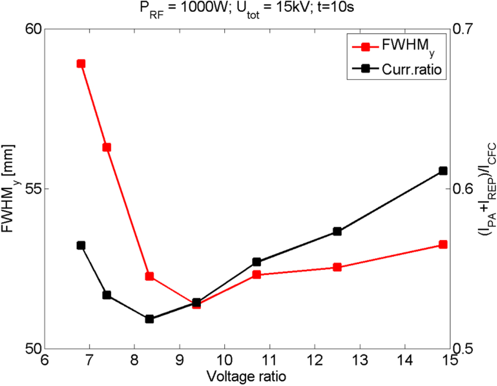
Beamlet divergence may not be directly assessed from the infra-red images, but as the total beam FWHM is expected to grow together with the beamlet divergence, the current ratio may be taken as a measure of divergence itself. By calculating the FWHM in the vertical direction of the beam thermal pattern on the CFC tile in a series of pulses performed with constant source parameters and total voltage, Utot but varying the extraction voltage Uex (extraction voltage scan), it is possible to compare the trend of FWHM and IPA/ICFC as functions of the voltage ratio, as shown in figure 10). The trends are found to be consistent as both variables are found to have a minimum for a voltage ratio of about 8–9 and to increase from this point either when increasing or decreasing Utot/Uex.
3.4. Measurement of beam space charge compensation or beam plasma interaction
For the self-consistent calculation of the space charge and beam plasma parameters in negative ion beams, one needs data on ion density, plasma potential, electron density and temperature before solving numerically the equations describing the two-dimensional plasma. Movable electrical probes were used to diagnose the beam potential of negative ion beams since the early 60 s. Generally speaking, interception of the primary beam by a probe perturbs the measurement especially at low gas densities. Gabovich and his team studied at different pressures the radial profile of beam potential and power density by using a combined thermocouples probes and collectors [151]. An example of the use of movable emissive probes is reported by Sherman and Allison [152]. More recently in low-energy positive beams, movable 4-pin double probes are used [153]¸ the probe support is a conductor to avoid charge-up of the internal insulator up to the beam potential. Voltage oscillations were measured using capacitive probes [154] or arrays of Langmuir probes suitably located to detect also the frequency-wavenumber spectrum [62]: diagnostic systems of this kind allowed the identification of the features of the waves excited during beam-gas interaction.
Retarding field energy analysers are an indirect non perturbing method, which analyses the particles emitted radially from the beam plasma, and allows to infer the plasma parameters from the energy distribution function of ions and electrons. One of the first examples is described in [155]; the technique is now commonly adopted for measuring the beam compensation degree, often in combination with other techniques [156–158]. For instance [159], describes the preparation of the retarding field energy analyser for NIO1; the system was applied to the investigation both of argon ions and electrons in a sputtering magnetron plasma showing the importance of numerical models for the interpretation of experimental results, particularly in collisional regimes, the system will be soon installed in NIO1.
Measuring the products of beam-gas interaction in particle accelerators has been done for 40 years, with ionisation profile monitors or residual-gas ionisation monitors (see for instance [160]): by applying a transverse electric field, residual-gas-ionisation monitors measure the line-integrated current of the secondary charge yield thus providing a time-resolved transverse beam profile (e.g. [161]); sometimes the target gas is constituted by a gas jet. This technique is mentioned here because, in high-intensity NBIs in which material objects cannot be inserted lest they would melt, such a non-destructive technique could provide the transverse intensity profiles of neutral beams after neutralisation (e.g. at the exit from the RID), besides being a direct measurement of reionisation losses (in the duct towards the tokamak plasma). Moreover, thanks to its bias, the diagnostic might reduce the flow of electrons towards the MITICA cryopanels. This topic deserves further investigations.
Electron beam probes were developed as a method to find the potential distribution of ion beams [162]. This technique offers a non-perturbing, line-integrated measurement of the electric field in the beam plasma, and can map the beam cross-section by sweeping the electron beam. The diagnostic is straightforwardly applied to small-diameter beams with cylindrical symmetry, however a more general use is suggested by recent improvements [163, 164]. A synergic study on space charge compensation of small multi-beamlet negative ion beams (such as NIO1) will profit from this diagnostic in combination with other indirect or perturbing techniques, such as those for single-beamlet positive ions, e.g. [165].
4. Conclusions
The present paper, after a brief introduction about the formation of high-intensity negative-ion beams, gives a comprehensive view of the interaction between the beam and the background gas. All related phenomena, like neutralisation of the beam and formation of a stationary plasma, are reviewed and their effect is assessed, by particularly exemplifying with MITICA (the prototype NBI for ITER), with SPIDER (the prototype source for ITER NBIs), and with NIO1 (a small and flexible negative hydrogen beam source). The numerical codes, necessary for the assessment of the various design choices, are described and the diagnostic techniques, used or designed with the purpose of investigating the beam parameters, are shown. Particularly, a successful integrated approach is adopted, involving the application of numerical codes to the simulation of the expected conditions and signals during the early operational phase of SPIDER, with the aim of assessing the capabilities of the diagnostic systems to characterise the SPIDER beam even during this phase and of providing the operator with the necessary information for the following operations. With these simulations indications to maximise the expected range of measurable quantities are obtained.
Acknowledgments
The work leading to this publication has been funded partially by Fusion for Energy. This publication reflects the views only of the authors, and F4E cannot be held responsible for any use which may be made of the information contained therein. The views and opinions expressed herein do not necessarily reflect those of the ITER Organization