


Abstract
Laser-driven ion acceleration potentially offers a compact, cost-effective alternative to conventional accelerators for scientific, technological, and health-care applications. A novel scheme for heavy ion acceleration in near-critical plasmas via staged shock waves driven by intense laser pulses is proposed, where, in front of the heavy ion target, a light ion layer is used for launching a high-speed electrostatic shock wave. This shock is enhanced at the interface before it is transmitted into the heavy ion plasmas. Monoenergetic heavy ion beam with much higher energy can be generated by the transmitted shock, comparing to the shock wave acceleration in pure heavy ion target. Two-dimensional particle-in-cell simulations show that quasi-monoenergetic  ion beams with peak energy 168 MeV and considerable particle number
  are obtained by laser pulses at intensity of
 in such staged shock wave acceleration scheme. Similarly a high-quality
  ion beam with a well-defined peak with energy 250 MeV and spread
  can also be obtained in this scheme.
Export citation and abstract BibTeX RIS

Original content from this work may be used under the terms of the Creative Commons Attribution 3.0 licence. Any further distribution of this work must maintain attribution to the author(s) and the title of the work, journal citation and DOI.
1. Introduction
High quality heavy ion beam generated from high-Z material can potentially be used for wide-ranging fields, including carbon ion-based fast ignition [1], injector for conventional heavy ion accelerators [2], nuclear reaction [3], study of exotic phenomenons in the interior of stars [4], and creation of quark-gluon plasma [5], etc. The advent of ultra-high intensity laser provides access to laboratory-sized compact ion accelerator via laser-plasma interactions. While the accelerations of protons and light ions have been extensively investigated, little has been reported on acceleration of heavy ions. In particular, the aforementioned applications [6] require the heavy ion beams have simultaneous high peak energy, high directionality, narrow energy spread, and high intensity flux, etc, which impose great challenges to the heavy ion acceleration.
Shock wave acceleration (SWA) [7–9] by ion reflection in near-critical plasmas is a promising candidate as a source of high quality ion beam. For the SWA in near-critical plasmas, the ions are continuously reflected to twice of the shock velocity during the shock wave stable propagation, resulting in production of intense quasi-monoenergetic ion beam with comparatively high particle number. These are in stark contrast to the target normal sheath acceleration [10–12], which typically produces an ion beam with exponential spectrum, large angular divergence, and low particle number. Furthermore, SWA can be achieved under a much relaxed experimental condition. This is also in contrast to the radiation pressure acceleration [13–18] which is exposed to various transverse instabilities and faces formidable experimental challenges. While for heavy ions with low Z/A, the shock velocity is slow due to the slow ion acoustic wave speed, i.e.,  , where Te is the electron temperature and mp is the proton mass. In addition, the condition for ion reflection, i.e.,
  , indicates the heavy ion reflection requires higher potential barrier given the same shock velocity, which limits the resultant beam density. Here e is the charge of electron,
  is the electrostatic potential of shock, and vs denotes the shock velocity. The quick dissipation by the heavy ion reflection further drags the shock wave during its propagation, which will significantly broaden the resultant energy spread.
In this paper, a staged SWA scheme for production of high quality heavy ion beam is proposed, where, a light ion layer is used in front of the heavy ion target. When the light ion layer is irradiated by an intense laser, a high-speed collisionless electrostatic shock wave is firstly launched. Before this shock arrives at the interface between the light and heavy ion plasmas, a strong electrostatic field is induced at the interface, resulting in early recirculation of hot electrons in the light ion layer and pre-acceleration of the heavy ions. Both of these effects lead to a much enhanced transmitted shock wave in the heavy ion plasma. The transmitted shock can reflect heavy ions which gives rise to a monoenergetic ion beam. These features and the exciting enhancement on the beam quality compared with the typical SWA in pure heavy ion plasmas are confirmed by two-dimensional PIC simulations. The resultant energy spectrum is adjustable by varying the mass density jump between the two adjoining plasmas.
This paper is organized as follows. In section 2, the theoretical model for the staged SWA are depicted. In section 3, the 2D PIC simulation results are presented to confirm our theory. In section 4, further insights into the staged SWA dynamics are given and the parameter range for optimal acceleration is proposed. In section 5, discussion on the experimental feasibility of our proposed scheme is given. Section 6 is dedicated to the conclusion.
2. Theoretical model
A schematic figure for the staged SWA dynamics is shown in figure 1. The front light ion layer is irradiated by intense laser, which drives a high-speed shock wave under the conditions of appropriate density piling-up and electron heating [9]. This laser-driven shock (black dashed line in figure 1(a)) is hereinafter referred to as 'the first shock'. A shock has the nature of compression due to the acceleration of the post-shock medium. So when the first shock strikes the interface, the heavy ion plasma is compressed and piled up under the action of the shock field Esh. A transmitted shock capable of reflecting heavy ions is thus formed (black dashed line in figure 1(b)). At the same time, either a shock wave or rarefaction wave (RW) is backscattered into the light ion layer. The character of the backscattered wave depends on the ion mass density jump between the two adjoining plasmas, i.e.,  , and their respective thermal properties [19]. In addition, the velocity of the transmitted shock increases with
  . Consequently, the resultant heavy ion spectrum in this staged SWA scheme can be adjusted by varying the density jump condition.

Figure 1. A schematic figure for the staged shock wave acceleration dynamics at moments (a) before the laser-driven shock arrives at the interface region and (b) after the transmitted shock is completely formed. The black solid lines represent the initial plasma density profile with electron density ne1 and ne2, respectively. The blue dashed lines are the electrostatic fields induced at the interface region (Eint) and the rear side (Esheath), respectively. The electric field associated with the shock front Esh is not shown here. The black dashed line in (a) is the laser-compressed ion density profile acting as the downstream of the laser-driven shock. Similarly, the black dashed line in (b) represents the downstream of the transmitted shock. The hot electrons move toward the rear side with relativistic velocity and a portion of them will be turned back under the action of Eint.
Download figure:
Standard image High-resolution imageIt is worth noting that there are some crucial merits in this staged SWA scheme. Before the first shock arrives at the interface where plasma density drops, the two plasmas expand into each other which induces an intense field Eint. On the other hand, hot electrons generated in the front laser-plasma interaction region move to the rear side and will enhance Eint by losing some kinetic energy when passing by the interface. A portion of the hot electrons even turn back under the condition  , where
  is the electron gamma factor, me is the mass of electron, c is the light speed in vacuum, and
  denotes the electrostatic potential across the interface. This early recirculation contributes to the uniform heating and accordingly a high temperature Te in the light ion layer. The high temperature promises a low Mach number given the same radiation pressure drive. So the light ion reflection is minimized in the first shock, which greatly benefits our staged SWA scheme. On the contrary, if large number of light ions are reflected in the first shock, e.g. in the case using short pulse or thick light ion layer, the laser energy will be heavily depleted. This effect decreases the transmitted shock velocity and the final energy conversion efficiency from laser into the reflected heavy ions.
It is noted that the heavy ion reflection is assisted by the pre-acceleration of heavy ions by Eint, because the upstream ions will become less energetic in the shock-rest frame. When the mass of electron is neglected, Eint can be estimated as  , where the pressure gradient
  and
and  . lint is the scale thickness of the interface region which is assumed to have the same order of Debye length, i.e.,
  with
with  ,
,  , and
, and  is permittivity constant of vacuum. After some algebra, Eint is given by

This indicates that Eint increases with the front layer density ne1 and density jump  (or
(or  ). When
  are sufficiently large,
  which does not sensitively depend on
  . So Eint has a weak scaling with
  in the high
  regime, which suggests that too large
  will not help further boosting the first shock velocity via Eint.
3. Two-dimensional PIC simulation results
The proposed novel acceleration scheme is confirmed by 2D PIC EPOCH simulations [20]. In the simulations, the laser pulse with wavelength  is polarized along y direction and propagates along
  direction. The transverse intensity distribution is a supergaussian (
 ) giving a full-width-at-half-maximum focal spot radius of
  centered at
  . The peak intensity
  corresponding to the normalized amplitude
  . The laser has a flat-topped temporal profile (i.e., constant intensity) with duration
  fs. The simulation box is
  in the (x, y) plane. The light and heavy ions are chosen to be fully ionized proton (
 ) and carbon (
 ) ions, respectively. In front of the heavy ion target is a
  thick proton layer with electron density
  . Here nc is the critical density
  , where
  is the laser frequency. The carbon target consists of a
  thick layer with density
  followed by a rear plasma with an exponentially decaying profile. So the light and heavy ion plasmas have a ion mass density jump
  . The decaying
  plasma, with a scale length of
  , guarantees a suitably smooth density gradient which leads to a mitigated and constant sheath field at the rear side (i.e., Esheath in figure 1). This effect benefits the generation of high quality ion beam in SWA [7, 9, 21]. The cell dimensions are resolved by the initial collisionless skin depth of light ion layer as
  and
and  , respectively, where
  . There are 64 particles per cell per species. With higher number of particles, the simulation results are converged.
Figure 2 shows the evolutions of transverse electric field Ey, proton density  , and carbon charge density
  , respectively. In our simulation, when the laser interacts with the front hydrogen layer, the density piling-up due to the radiation pressure compression is obvious, see
  at t = 100 fs (purple part in figure 2(a)). The piling-up ultimately evolves into a collisionless electrostatic shock wave whose front can be observed in figures 3(a) and (d). With the density jump, a strong electric field Eint (figure 3(d)) is induced at the interface as expected in theory. The simulation shows that
  which is comparable to the first shock field
  . On the other hand, the temperature is measured to be
  , so
, so  . The scale length of the interface region is measured to be
  . It suggests
  from equation (1), which agrees well with the simulation result. Eint can accelerate both
  and
and  before the arrival of the first shock. This pre-acceleration makes it more feasible for the
  ion reflection, because these
  ions will become less energetic in the shock-rest frame.

Figure 2. The spatial distributions of the transverse electric field Ey, proton density  , and carbon ion charge density
  in the simulation in which staged shock waves are driven by intense laser in near-critical plasmas. The peak laser intensity is
  and electron density in the front proton layer is
  . The electron density jump between the adjoining plasmas are
  (i.e.,
  ). The three snapshots are taken at (a) t = 100 fs, (b) t = 233 fs, and (c) t = 600 fs, respectively. The electric field is normalized by
  and density by nc.
Download figure:
Standard image High-resolution image
Figure 3. Results from the same simulation as in figure 2 at the same corresponding moments. (a)–(c) show the spatial distribution of longitudinal field Ex. (d)–(f) show the  ion phase space (px − x). The red line represents the spatially averaged Ex (along a
  average over y centered at
  ). The momentum is normalized by mic, where mi is the mass of carbon ion.
Download figure:
Standard image High-resolution imageWhen the first shock is striking the interface, a superposition of Esh and Eint is observed (figures 3(b) and (e)) which leads to a very strong field ( ). The
  layer is profoundly accelerated and compressed which shows the enhanced compression ability of the current shock. The large
  piling-up can be seen in figure 2(b). Consequently, the first shock is being transmitted into the
  plasma and the
  ion reflection starts (see its phase space in figures 3(e) and (f)). With the current simulation setup, a RW is backscattered into the proton layer resulting in a much rarefied hydrogen plasma (purple part in figure 2(b)).
After the first shock is completely transmitted into the  plasma, the transmitted shock front is clearly shown in figures 2(c) and 3(c). The plateau in phase space (figure 3(f)) indicates a monoenergetic
  ion beam has been produced. For comparison with the staged SWA case, another PIC simulation, in which a target made up of pure
  plasmas with thickness
  and electron density 10nc, are performed. Other parameters are kept unchanged. The energy spectra of both cases are compared in figure 4(a). In the staged SWA case (red line,
  ), due to the lower density of the
  layer, the number of reflected
  ions (
 ) is about one half of that in pure carbon case (
 , green line). The spectrum in pure carbon case barely shows a peak with energy
  and spread up to be
  . In striking contrast, the spectrum in the staged SWA case shows a well-defined peak with
  and
and  . The strong adaptability of this staged SWA scheme is confirmed by replacing the carbon ions by heavier aluminum (
 , A = 27,
  ) and keeping other parameters unchanged. The results (figure 4(b)) also indicate a high quality
  ion beam with well-defined peak of
  and
and  is generated in the staged SWA case. While in the comparison case with pure aluminum plasma, the spectrum shows a small peak with
  and spread up to be
  . These simulations show that both the peak energy and spread, through our novel scheme, are greatly improved compared with the typical SWA in pure heavy ion plasmas.
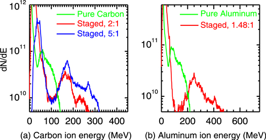
Figure 4. (a) Carbon ion spectra in the staged SWA cases with ion mass density jump of  (red line, corresponding to
  as in figures 2 and 3) and 5/1 (blue line), respectively. The green line depicts the spectrum from the comparison case with pure carbon plasma. (b) Aluminum ion spectra in the staged SWA case with
  (i.e.,
  , red line) and in the comparison case with pure aluminum plasma (green line), respectively. The heavy ions for the above spectra are selected within a
  spatial range over y direction centered at
  .
.
Download figure:
Standard image High-resolution image4. Analysis of the acceleration dynamics and the parameters for optimal acceleration
The essential idea of the staged SWA scheme is that the formation of the shock wave in heavy ion plasmas is separated from the intense driving laser. Two merits based on this separation should be pointed out. First, we could apply very intense laser in the light ion layer to drive a high-speed shock. Having high charge-to-mass ratio Z/A, the light ions can respond to the electrostatic field quickly and accordingly have sufficient piling-up. This mechanism for remaining relativistically opaque by large piling-up and obtaining a high-speed shock wave is similar with the idea in reference [22]. Second, the heavy ion layer could have relatively low density which leads to a stable shock velocity with mild dissipation. While in the typical SWA scheme using pure heavy ion plasma with high density, the continuous reflection of heavy ions will impose a strong loading for the shock structure. This loading will drag the shock and diminish the corresponding potential  dramatically. The declination in shock velocity (figure 5(b)) will result in a progressive broadening effects on the ion spectrum (green line in figure 4(a)).

Figure 5. (a) The black, green, and red solid lines represent the total energy of all electrons,  ions, and
  ions, respectively, in the staged SWA case (as in figures 2 and 3). The black and red dashed lines represent the total energy of all electrons and
  ions in the comparison case with pure carbon plasmas. Blue line depicts the laser energy for both cases. Ion energies are multiplied by a factor of 10. (b) The phase space of
  ions in the comparison case with pure carbon plasma at t = 800 fs. The dashed rectangle shows that the shock velocity is declining significantly with the dissipation by reflecting large number of
  ions.
ions.
Download figure:
Standard image High-resolution imageThe energy evolution in the whole simulation box offers further insights into the staged SWA mechanisms, see figure 5(a). The laser energy (blue line) is continuously injected into the system until it is switched off. The electron energy (black solid line) increases sharply with the effective heating by  effects, plasma waves excitation, etc. The
  population gains energy (green solid line) mainly through the laser-induced electrostatic field during the ponderomotive force compression stage and the first shock propagation. After
  fs, the total energy of
  (red solid line) increases rapidly due to the acceleration of
  ions (figure 3(e)). The growth rate of the total
  energy in staged SWA case is higher than the pure carbon case (red dashed line), because the transmitted
  shock in staged SWA case is much faster. This is also consistent with their peak energy difference (figure 4(a)). The final value of the total
  energy is higher in staged SWA case which shows the enhancement of the energy conversion efficiency (blue line in figure 6(b)). After the laser is off (∼267 fs), the total
  energy gain approaches a saturated level in the pure carbon case. This is because the shock will lose its momentum rapidly when it is reflecting large number of heavy
  ions. While in the staged SWA case, the transmitted
  shock has a relatively stable velocity with mild ion reflection when propagating in lower density plasma.

Figure 6. Results from a series of 2D PIC simulations for staged SWA scheme with the same laser intensity 
 and front proton layer (
 ). The heavy ion target is chosen to be
  plasmas. (a) The dependences of the peak energy E0 (black solid circle) and the corresponding spread
  (blue solid square) of the
  ion beams on the ion mass density jump
  . The horizontal dashed lines are the results from comparison simulation with pure carbon plasma (black for E0 and blue for
  ). (b) Corresponding to (a), the dependences of the reflected
  number N (black solid circle) and the energy conversion efficiency (blue solid square) from laser to the reflected
  on
on  . The horizontal dashed lines are results from comparison simulation with pure carbon plasma (black for reflected
  number and blue for the energy conversion efficiency).
Download figure:
Standard image High-resolution image
The property of the transmitted shock mainly depends on the ion mass density jump  [19], which lays the theoretical foundation for the adjustability of heavy ion spectrum by varying
  in the staged SWA scheme. So a series of PIC simulations are performed to study the parameter range for optimal staged SWA. Figure 6(a) shows the dependences of peak energy E0 (black solid circle) and spread
  (blue solid square) of the
  ion beams on
  . It indicates that E0 in all of the staged SWA cases increase with
  as expected, and is also superior to the comparison case (60 MeV, black dashed line).
  shows the similar trend with
  and advantage over the comparison case (73%, blue dashed line). It is noted that the improvements of E0 and
  still exist even without the help of ion mass density jump (see the cases with
  and
and  ). In addition, in the case with
  (i.e.,
  ), there is no interface-induced field Eint which could enhance the first shock velocity, but the peak energy (∼72 MeV) is still enhanced. So the light ion layer used in staged SWA scheme does help in boosting the final heavy ion energy.
Figure 6 shows that the range of  for optimal staged SWA scheme lies in
  . In this range, both E0 and
  are greatly improved compared with the SWA in pure carbon plasma. At the same time, the reflected
  ion number and the energy conversion efficiency increase with
  dramatically (figure 6(b)). For example, in the case with
  , E0 is boosted to be 174 MeV and
  drops to be only 22%. In addition, the ion beam has a considerable particle number of
  and high conversion efficiency of
  . It is noted that very intense Eint is established in this case due to large density jump (equation (1)). More hot electrons will be turned back by Eint which leads to high Te in the front layer. Such high temperature and intense Eint give rise to fast expansion of the proton layer, so the laser will penetrate the target when the first shock is striking the interface. Large number of hot electrons will be generated and expand into vacuum. This leads to a strong sheath field which accelerates the upstream
  plasma. Such acceleration effects will help more upstream ions to be reflected by the transmitted shock, because the accelerated ions will become less energetic in the shock-rest frame. This explains the high particle number and high conversion efficiency in this case. But another two problems will arise for the high density jump regime (
 ). First, the velocity of the reflected
  ions is given by
  in the non-relativistic limit, where v0 is the expanding velocity of the upstream plasma. Consequently, the peak energy can no longer be boosted to a much higher value with larger
  , as the expanding velocity v0 cancels out part of the velocity gain by shock reflection. This explains the limited gain of the peak energy from the case with
  to the case with
  (figure 6(a)). Second, some reflected particles will obtain more energy under the action of the intense sheath field, which leads to the high energy tail in the spectrum (blue line in figure 4(a)). So, too large
  is not suitable for the high quality ion beam generation.
5. Discussion on experimental feasibility
With the rapid progress of target fabrication technology, targets of relativistically near-critical density ( , corresponding to laser with short wavelength) are not only makable but also controllable through various methods in experiments to date. Hydrogen target at density of
  , which has been produced either by extrusion from a liquid-helium-cooled cryostat [23] or by a cooling finger from a cryogenic system [24] in laser-plasma experiments, can be used as the low-Z layer in the staged SWA scheme. Foams with high hydrogen concentration can also provide well-characterized uniform density and temperature near-critical plasmas [25, 26]. As for the carbon target, carbon nanotube foams [27] can provide spatially well-defined carbon plasmas with electron densities at
  , which are very close to those used in the simulations of this paper. The exponentially decaying profile [8, 9, 28] at rear side of the target can be produced through the thermal expansion of the carbon target via either a low-power pre-heater pulse or a separate low-intensity ultraviolet (UV) laser [29], where the density scale length can be controlled via adjusting the expansion time of the carbon target, i.e., the delay time between the main pulse and the pre-heater pulse or the UV beam.
The proposed staged SWA scheme in this paper is rather robust. The basic physics of this scheme will not change even if the preplasma effect is take into account. The latter can influence the maximum piling-up of plasma density and the electron heating during the shock formation process [9]. The precise dependence of the resultant beam quality on the preplasma needs further systematic investigation. Another consideration is for the presence of non-planar interface between light and heavy ion plasmas. The non-planar interface may lead to spatially non-uniformity and modulate the transmission of the first shock into the heavy ion target, increasing the angular divergence of the shock-reflected heavy ions. In practical experiments, using a comparatively large spot size of the laser pulse, including the main pulse and the separate UV beam (for creating required plasma profile as stated above), can suppress this potential detrimental effect.
6. Conclusion
In this paper, a novel heavy ion acceleration scheme via staged shock waves is proposed in which a light ion layer is deployed in front of the heavy ion target. When the laser-driven shock in the light ion layer is transmitted into the heavy ion target, a quasi-monoenergetic heavy ion beam is generated. The resultant ion spectrum can be adjusted by varying the ion mass density jump between the adjoining plasmas. The interface-induced field Eint can enhance the first shock velocity and amplitude, which greatly benefits the ensuing heavy ion acceleration. 2D PIC simulations have confirmed our theory and show that a  ion beam with peak energy of 168 MeV and considerable particle number of
  can be obtained in the staged SWA scheme with
  at the laser intensity of
 . This acceleration scheme also applies to heavier ion species, such as
  ion beam with well-defined peak of
  and
and  can be generated in the staged SWA scheme with the same laser.
Acknowledgments
This work is supported by the National Natural Science Foundation of China, Nos. 11575298, 91230205, 11575031 and 11175026, the National Basic Research 973 Project, Nos. 2013CBA01500 and 2013CB834100, the National High-Tech 863 Project and the National Science Challenging Program. B Q acknowledges the support from Thousand Young Talents Program of China. The comments of the anonymous referees are appreciated. The computational resources are supported by the Special Program for Applied Research on Super Computation of the NSFC-Guangdong Joint Fund (the second phase).