


Abstract
The nuclear spin gyromagnetic ratio can be enhanced by hyperfine coupling to the electronic spin. Here we show wide tunability of this enhancement on a 15N nuclear spin intrinsic to a single nitrogen-vacancy center in diamond. We perform control of the nuclear spin near the ground state level anti-crossing (GSLAC), where the enhancement of the gyromagnetic ratio from the ground state hyperfine coupling is maximized. We demonstrate a two order of magnitude enhancement of the effective nuclear gyromagnetic ratio compared to the value obtained at 500 G, a typical operating field that is suitable for nuclear spin polarization. Finally, we show that with strong enhancements, the nuclear spin ultimately suffers dephasing from the inhomogeneous broadening of the NMR transition frequency at the GSLAC.
Export citation and abstract BibTeX RIS
1. Introduction
Advancements in quantum computation have been accelerated by the development of qubits with high fidelity quantum control and long quantum coherence times [1, 2]. The nuclear spin degree of freedom has long been considered to be a good candidate for a qubit [3–5]. Since the nuclear spin has a relatively small gyromagnetic ratio  compared to that of an electron (approximately 1000× smaller than that of an electron), it is well-protected from decoherence sources in the environment. Impressive coherence times up to six hours have been achieved in solid-state systems using the nuclear spin as a quantum memory [6–11].
Despite the long coherence time, fast nuclear spin manipulation is difficult as the small gyromagnetic ratio of the nuclear spin also isolates the spin from the control fields. Several experiments on nitrogen-vacancy (NV) centers have shown that nuclear spins coupled to a NV center can exhibit Rabi oscillations that are significantly faster than the expected oscillations of a bare nuclear spin that is driven by the same AC magnetic field. This faster rotation rate can be interpreted as an enhancement of the effective nuclear gyromagnetic ratio ( ) that results from hyperfine interactions with the NV electronic spin in the ground state. The enhancement factor of ∼20 is typically achieved at the excited state level anti-crossing (ESLAC), where the nuclear spin can be optically polarized [12–14].
In this article, we extend these earlier works and show that the enhancement of the nuclear spin gyromagnetic ratio in the NV system is widely tunable by varying the electronic spin transition frequency. The enhancement is observed by directly measuring the nuclear spin Rabi frequency as a function of AC magnetic field drive amplitude and comparing to the value expected from a bare nuclear spin driven under the same conditions. The result is in good agreement with the theoretical predictions [15]. We carefully study the behavior near the ground state level anti-crossing (GSLAC), where the enhancement is maximized. We demonstrate enhancements as large as 2000, a more than two order of magnitude improvement over previous work.
Naturally, the increased control speed comes with the cost of faster spin decoherence, as the spin is more susceptible to the magnetic fields in the environment [16]. We therefore measure the dephasing rate of the nuclear spin as a function of the external magnetic field near the GSLAC. Our results show that the dephasing rate in our experimental settings is limited by fluctuations in the DC magnetic field, which is amplified due to the increased effective nuclear spin gyromagnetic ratio at the GSLAC.
2. Enhancement of the nuclear gyromagnetic ratio in a NV center
Coherent dynamics of the coupled electron and nuclear spins in the NV system have been demonstrated in reference [12], where Childress et al observed an enhanced Larmor precession frequency of 13C nuclear spins in close proximity to the NV center. The enhancement factor,  , explained by second-order perturbation theory, however, is sensitive to the external magnetic field and increases rapidly near the GSLAC. Recently, the exact expression of the enhancement has been presented in reference [15]. We briefly describe their derivation in this section.
The enhancement of the effective nuclear gyromagnetic ratio can be understood by considering the NV center Hamiltonian H = H0 + V, with its secular terms H0, and non-secular terms V given by:


Here ge (gN) is the electronic (nuclear) g-factor,  (
( ) is the Bohr (nuclear) magneton,
  is the external magnetic field, and
  (
( ) are the electron (nuclear) spin operators. Hyperfine couplings are given by the matrix components Aij, where
  . Raising and lowering operators are defined as
  ,
,  ,
,  . Electronic spin states mS = 0 and
  are separated by
  , where
  is the ground state zero-field splitting and
  is the Zeeman shift from the external magnetic field Bz applied along the NV symmetry axis (
 ). For each electronic spin state, the energy levels split into two sublevels by the 15N nuclear Zeeman shift (
 ) and the electron-nuclear axial hyperfine coupling
  further separates the two mI states of the 15N nuclear spin in the
  subspace. The perpendicular hyperfine terms
  mix the states with zero-quantum (ZQ) transitions, specifically
  and
and  . Off-diagonal terms of the matrix A are zero due to the symmetry of the NV center [9, 13, 17].
Chen et al [15] showed that the Hamiltonian can be diagonalized by rotating the two ZQ subspaces with a unitary transformation  , where
  ,
,  and the rotation angles are given by:


By applying the transformation UZQ on the interaction Hamiltonian in the rotating frame,  , and keeping only the terms that contribute to nuclear spin flips, one can obtain:

Here  represents the enhancement factors in each NV electronic spin manifold mS and their exact expressions are given by:


In contrast to second-order perturbation theory, where the enhancement  is infinite near the GSLAC, these exact expressions predict a finite enhancement near the GSLAC with the maximum value of
  . However, it is still unclear what ultimately limits the nuclear spin control speed near the GSLAC, where the enhancement is maximized. Therefore, we carefully measure the enhancements near the GSLAC, compare our measurements and theory, and investigate how this enhancement of the nuclear spin gyromagnetic ratio affects the nuclear spin coherence time.
3. Experiments
Our quantum system consists of a NV electron spin and the intrinsic 15N I = 1/2 nuclear spin. The sample is an electronic grade diamond (Element Six). The NV centers are created via 20 kV ion implantation of 15N atoms into the 100-nm, isotopically enriched layer (12C > 99.99 %) that is grown on top of the bulk sample [18]. The implantation depth is estimated to be  from stopping and range of ions in matter (SRIM) simulations [19]. The schematic of the experimental setup is illustrated in figure 1(a). The array of 15N implanted sites is surveyed using a room-temperature confocal microscope with a 532 nm excitation laser. For this study, we select an arbitrary site containing a single NV center, as confirmed by
  measurements. We also verify via optically detected magnetic resonance (ODMR) that there are no nearby nuclear spins coupled to this NV. Photoluminescence (PL) from the NV center is collected using a high numerical aperture (NA = 0.95) objective and directed towards single photon detectors using a combination of fiber and free space optics [14]. The DC magnetic field along the NV axis is controlled by the combination of a permanent magnet mounted on a three-axis translation stage and electromagnets that are aligned perpendicular to the NV axis. Off-axis magnetic field components arising from misalignment of the permanent magnet are compensated using these electromagnets with an accuracy better than 0.1 G. The AC magnetic field is delivered to the sample via a Ti/Au stripline that is fabricated on the diamond surface. Microwave (MW) and radio frequency (RF) pulses are applied through this stripline to drive electronic and nuclear spin rotations. The circuit diagram is shown in figure 1(b). A SRS SG394 (Aglient 33522A) signal generator is used to generate MW (RF) pulses. The MW signal is amplified with a broadband amplifier (Triad RF TA1003) to allow for fast manipulation of the electronic spin. MW and RF signals are combined with a resistive splitter-combiner before they are delivered to the sample. We calibrate the magnetic field amplitude of the RF pulse, BRF, by performing AC magnetic field sensing with electron spin echo. Details of this calibration are given in appendix

Figure 1. (a) Schematic of the setup and a confocal image of the sample implanted with 15N. The circle indicates the NV used in this experiment. An on-chip Ti/Au stripline was fabricated on the sample to drive MW and RF control pulses on the NV center. A permanent magnet was aligned to produce a static magnetic field along the NV axis  , indicated by the red arrow. (b) Circuit diagram: two signal generators, SRS SG394 and Agilent 33522A, are used to generate MW and RF pulses, respectively. The signals are combined with a resistive splitter/combiner before being delivered to the sample. (c) NV center energy level diagram: The electronic spin levels mS = 0 and
  are separated by
  . A selective MW pulse is tuned to resonance with the
  =
=  to
to  transition for initialization and readout of the nuclear spin qubit. A RF pulse is tuned to resonance with the
  to
to  transition to drive nuclear spin Rabi oscillations. (See text for details.) (d) PL as a function of
  showing the electronic spin transitions associated with each nuclear spin projection.
Download figure:
Standard image High-resolution imageThe energy level diagram of our system is depicted in figure 1(c). We select two well-isolated sublevels  ,
,  to demonstrate nuclear spin rotations. The two states can be addressed with a RF pulse (frequency
  ) driving a direct NMR transition. To read out the nuclear spin state, we map the nuclear spin state to the electronic spin state by applying a selective MW π-pulse (frequency
  ) tuned to resonance with the
  transition at the end of the nuclear spin control sequence. The electronic spin state is then read out by optical excitation [7, 13].
To probe the electronic spin transition frequencies, we performed ODMR spectroscopy by applying pulsed MW excitation with varying frequency  and monitoring the PL during a subsequent laser excitation. When
  is on resonance with an electronic transition, we observe a dip in the PL intensity as a result of the population transfer from mS = 0 to
  . Figure 1(d) shows an example of a PL spectrum measured as a function of the MW detuning
  relative to the electronic spin splitting
  (
( ). The two resonances are separated by the hyperfine coupling to the 15N nuclear spin,
  [20].
[20].
4. Nuclear Rabi oscillations and effective nuclear gyromagnetic ratio
We perform nuclear Rabi experiments with the pulse sequence illustrated in figure 2(a). We start by optically pumping the electron and nuclear spins with a 4  long 532 nm laser pulse [21]. After the system is polarized into the
  state, a selective MW π-pulse is applied to transfer the population to the
  state, completing the initialization process. We then drive nuclear spin Rabi oscillations by applying a RF pulse with varying duration
  resonant with the
  to
to  transition. We note that while the nuclear Rabi oscillation contrast is maximized at the ESLAC, as the optical polarization is most effective, we can still obtain nuclear Rabi oscillations with a reduced contrast away from the ESLAC, where imperfect optical polarization occurs. Finally, optical readout is performed by applying another selective MW π-pulse that converts the population from
  to the bright state
  . This yields a PL signal that is proportional to the
  population at the end of the pulse sequence.

Figure 2. (a) Pulse sequence for NMR spectroscopy and nuclear Rabi oscillations. (See text for details.) (b) and (c) A sample of NMR spectroscopy and Rabi oscillation data taken at the ESLAC (512.3 G).
Download figure:
Standard image High-resolution imageWe probe the nuclear spin transition frequency  using this same pulse sequence. Using low RF power, the nuclear spin rotation is only effective when
  is close to
  . Figure 2(b) shows PL as a function of
  at
at  , showing the decrease in PL at
  . Then, we perform nuclear Rabi nutations by varying the RF duration
  . Typical nuclear spin Rabi oscillations with
  are shown in figure 2(c). The nuclear Rabi frequency
  we extract from the data exceeds the expected value from a bare nuclear spin
  by a factor of ∼18.5, indicating an enhancement of the effective nuclear gyromagnetic ratio.
Plotting the nuclear Rabi frequency  as a function of
  for a series of DC magnetic fields Bz (see figures 3(a) and (b)), we see that for each value of Bz,
  scales linearly with
  . As the Rabi frequency increases beyond
  , the scaling starts to deviate from the linear behavior and saturates at
  before the dynamics become non-sinusoidal (see appendix
  is comparable to the hyperfine splitting Azz. We extract the effective nuclear gyromagnetic ratio
  by linear fitting the data and obtaining the slopes. Fitting of each data set is extended to the largest values of
  where the fit maintains over 95% confidence (
 ). The data also confirms the DC magnetic field is well aligned with the NV axis, as there is no visible offset at
  that would result from an off-axis magnetic field
  .
.

Figure 3. Nuclear spin Rabi frequency as a function of RF amplitude (a) below the GSLAC and (b) above the GSLAC. (c) Extracted nuclear gyromagnetic ratio from (a) and (b). The gray curve shows the effective nuclear gyromagnetic ratio calculated from the theory described in section 2.
Download figure:
Standard image High-resolution imageIn figure 3(c) we plot  extracted from the slopes in figures 3(a) and (b) as a function of Bz. We achieved enhancements
  exceeding 2000 near the GSLAC (
 ), making it possible to perform a full nuclear spin
  rotation within a microsecond with less than
  of RF power applied to the stripline. This enhancement is more than two orders of magnitude greater than the results obtained on NVs at lower magnetic fields near the ESLAC [13] and is in excellent agreement with the expression given in equation (8), where the theoretical maximum enhancement is
  .
.
5. Nuclear spin dephasing
While the largest enhancement of the nuclear gyromagnetic ratio is obtained near the GSLAC, where the nuclear spin can also be polarized via optical pumping, the GSLAC spin mixing responsible for nuclear polarization also affects the coherence time of the nuclear spin. We therefore investigate the behavior at the GSLAC by examining the coherence of the nuclear spin via nuclear spin Ramsey experiments. Here, after initialization of the nuclear spin, a RF  -pulse on resonance with
  is applied to create a superposition state
  . The state is then allowed to freely precess for a duration
  before another RF
  -pulse rotates the nuclear spin state back to the measurement basis. We manually shift the phase of the second RF
  -pulse linearly as a function of
  , relative to the first pulse, to create visible Ramsey fringes. Figures 4(a) and (b) show the nuclear spin Ramsey data near the ESLAC (512.3 G) and the GSLAC (1032.1 G), respectively. From each data set, we extracted the dephasing time
  from the gaussian decay envelope. We found that while the change in the external magnetic field from the ESLAC to the GSLAC results in over 50× improvement of the effective nuclear spin gyromagnetic ratio, it also results in a 10× increase in the nuclear spin dephasing rate
  .
.

Figure 4. Nuclear Ramsey fringes acquired at (a)  and (b)
  show a reduction of
  near the GSLAC. The data are fitted with a sinusoidal function with a Gaussian decay. (c) NMR Frequency
  as a function of Bz showing a nonlinearity near the GSLAC. Each data point is labeled according to the data sets in figure 3. Blue curves show the theoretical values derived by diagonalizing the NV Hamiltonian. (d) Blue curves: The derivative of the NMR frequency shown in (c) with respect to the magnetic field
  characterizes the sensitivity of the nuclear spin to the magnetic field along the NV z-axis. The data points show the dephasing rate
  extracted from Ramsey experiments. The increase in the nuclear spin dephasing rate is in good agreement with the increase in magnetic field sensitivity.
Download figure:
Standard image High-resolution imageThis increased nuclear spin dephasing rate can be explained by considering the inhomogeneous broadening of the nuclear spin transition (frequency  ). Near the GSLAC, hybridization of electronic spin and nuclear spin results in the NMR frequency shift that deviates from a simple linear nuclear Zeeman shift, as shown in figure 4(c). This hybridization causes a significant increase in the effective longitudinal gyromagnetic ratio
  around the GSLAC. As a consequence, the nuclear spin suffers larger inhomogeneous broadening from the same DC magnetic field fluctuation and thus results in the shorter
  . Figure 4(d) shows that the increase in the dephasing rate
  is in good agreement with the increase in
  , confirming that our
  is limited due to the DC magnetic field fluctuations
  . This is attributed to the thermal drift from
  room temperature fluctuations. These magnetic field fluctuations could be reduced by improving the stability of the setup and adding extra magnetic shielding from the environment [6].
6. Summary
We have shown that the effective nuclear spin gyromagnetic ratio can be greatly enhanced due to hyperfine coupling of the nuclear spin to the NV electronic spin. Our approach is also applicable to other coupled electron-nuclear spin systems, such as phosphorous donors in silicon or rare-Earth ion dopants in crystalline hosts [10, 22], where it would allow for rapid quantum control of nuclear spins without requiring high RF power. We observe the strongest enhancement near the GSLAC, where we achieve more than a factor of 2000 enhancement of the effective nuclear gyromagnetic ratio over the bare nuclear gyromagnetic ratio. Ultimately, as the enhancement increases rapidly near the GSLAC, the spin coherence suffers from the inhomogeneous broadening of the NMR frequency and more complicated dynamics occur as the Rabi frequency approaches the NMR frequency.
Acknowledgments
The experiments at Princeton were funded by the David and Lucile Packard Foundation, the Gordon and Betty Moore Foundation's EPiQS Initiative through Grant GBMF4535, and the National Science Foundation (DMR-1409556 and DMR-1420541). BAM acknowledges support from a Department of Defense fellowship (NDSEG) and an IBM PhD fellowship. CAM acknowledges support by the National Science Foundation Graduate Research Fellowship under grant DGE–1144085. DDA acknowledges support by the National Science Foundation through NSF DMR-1306300.
Appendix A.: Calibration of 

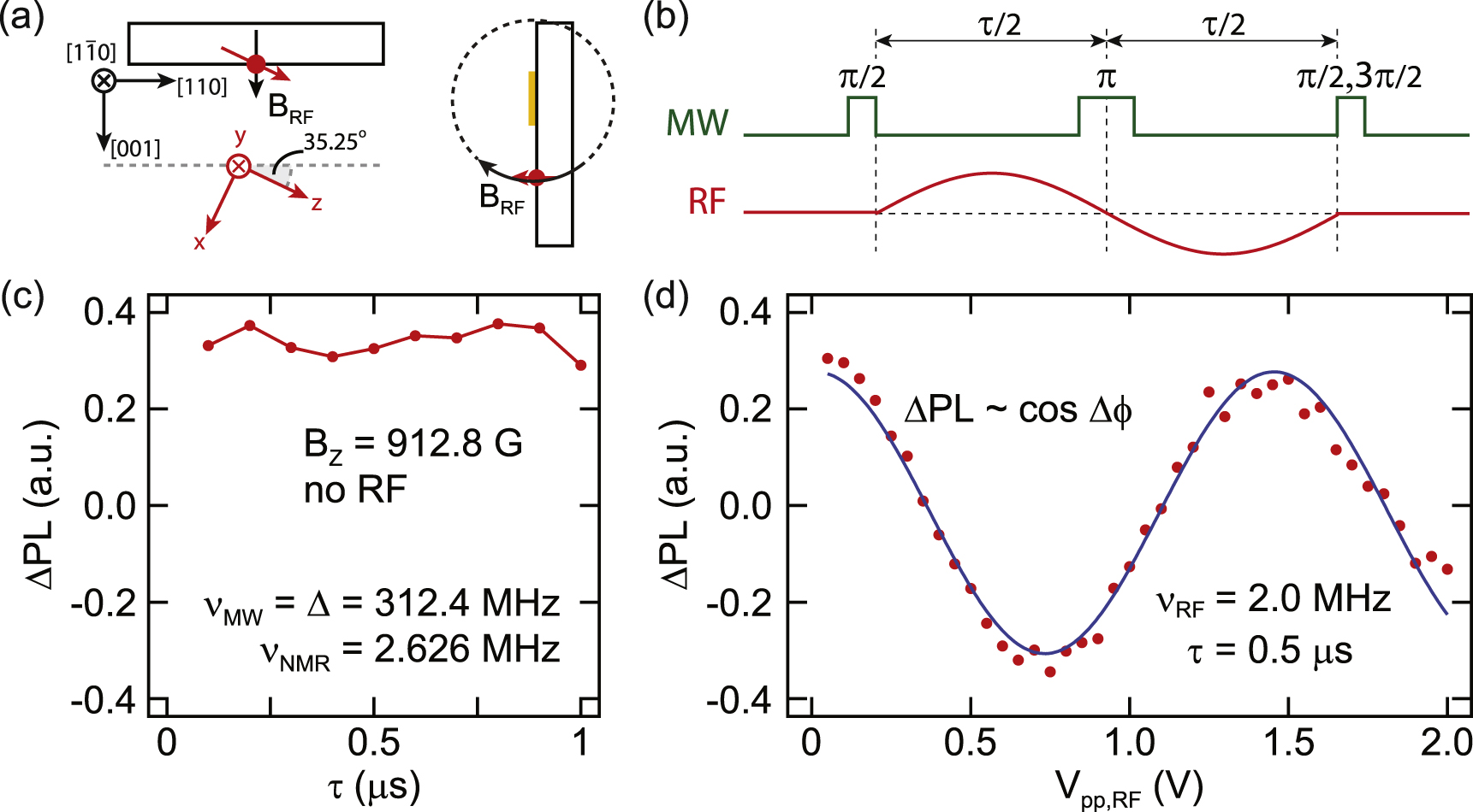
To calibrate the amplitude of the field  , we perform AC magnetic field sensing using an electron spin echo technique. The geometry of our sample is depicted in figure A1
(a). The orientation of our stripline provides
, we perform AC magnetic field sensing using an electron spin echo technique. The geometry of our sample is depicted in figure A1
(a). The orientation of our stripline provides  along the xz-plane at the NV center used in this experiment. We perform spin echo measurements on the electronic spin while simultaneously applying a RF pulse during the free precession time of the electron. The experimental sequence of our spin echo sensing scheme is depicted in figure A1(b). The final pulse was set to either a
  pulse or a
  pulse and the results were subtracted to obtain the spin echo contrast. This spin echo scheme provides an advantage over a Ramsey-type sequence by canceling out all the quasi-static magnetic fields on the time scale of the free evolution time τ. We adjust τ to match the period of the RF pulse
  , so that the phase accumulation
  from the RF pulse is maximized. With this choice of free evolution time,
  is given by equation (A.1) [23].

We perform this AC magnetic field sensing at  , an intermediate field between the ESLAC and the GSLAC, where the nuclear spin is not polarized. We choose
  , far detuned from the NMR frequency
  . This corresponds to
  , much shorter than the coherence time of the electronic spin of the NV center in an isotopically purified substrate, as shown by the lack of any spin echo decay during this time when no RF is applied (see figure A1(c)). Fixing
  , we apply the RF pulse and monitor
  as a function of RF amplitude
  . This results in the modulation in the spin echo contrast according to the phase accumulated, projected on to the z-axis of the Bloch sphere,
  .
.

Figure A1. (a) Geometry of the sample: an on-chip stripline is fabricated such that the magnetic field  is directed perpendicular to the (100) surface of the diamond. (b) Spin echo sequence for sensing BRF: a RF pulse is applied immediately after the preparation of the electronic spin superposition state and the free precession time τ is chosen to match the RF pulse period. (See text for details.) (c) Standard spin echo signal showing no decay of the PL contrast
  for
for  with no RF applied. (d) Spin echo contrast at
  with 2 MHz RF applied. The phase accumulated results in modulation of the spin echo contrast.
Download figure:
Standard image High-resolution imageFigure A1(d) shows the modulation from the AC magnetic field sensing scheme. From the cosine fit, we obtain  , corresponding to
  . Considering the geometry from the sample orientation ({100}-face,
  edge) (see figure A1(a)), we then obtain the magnitude of
  .
.
Appendix B.: Strong driving limit of nuclear Rabi oscillations
As the amplitude of the RF field driving the NMR transition increases, we found that while the nuclear Rabi frequency can increase beyond  , the scaling of Rabi frequency as a function of the drive amplitude starts to deviate from the linear behavior and saturates at
  , as shown in figures B1
(a) and (b).
, as shown in figures B1
(a) and (b).

Figure B1. Nuclear spin Rabi frequency as a function of RF amplitude (a) below the GSLAC and (b) above the GSLAC, showing the saturation behavior around  . (c) Nuclear Rabi oscillations obtained close to the GSLAC with a small drive amplitude are sinusoidal. (d) Non-sinusoidal behavior is observed at the same DC magnetic field as in (c), but with a larger drive amplitude.
Download figure:
Standard image High-resolution image
In addition to this saturation behavior, we also observe that the dynamics become non-sinusoidal at strong driving fields. Figure B1(c) shows nuclear Rabi oscillations obtained near the GSLAC ( ,
,  ) where we obtain standard sinusoidal behavior with the drive amplitude
  . As we increase the drive amplitude to
  , the dynamics of the nuclear spin oscillations become non-sinusoidal, as shown in figure B1(d). We attribute this to the breakdown of the rotating wave approximation, and to the fact that our RF field contains both
  and
and  . Near the GSLAC, the z-component
  can also contribute to the level shifts of both ESR and NMR transitions. This effect can result in more complicated Landau–Zener-like dynamics that are beyond the scope of this paper. In principle, the complicated dynamics could be mitigated by engineering the sample geometry such that the RF field is perpendicular to the NV axis [9].