


Abstract
We demonstrate that a single-layer graphene replicates the shape of DNA origami nanostructures very well. It can be employed as a protective layer for the enhancement of structural stability of DNA origami nanostructures. Using the AFM based manipulation, we show that the normal force required to damage graphene encapsulated DNA origami nanostructures is over an order of magnitude greater than for the unprotected ones. In addition, we show that graphene encapsulation offers protection to the DNA origami nanostructures against prolonged exposure to deionized water, and multiple immersions. Through these results we demonstrate that graphene encapsulated DNA origami nanostructures are strong enough to sustain various solution phase processing, lithography and transfer steps, thus extending the limits of DNA-mediated bottom-up fabrication.
Export citation and abstract BibTeX RIS

Original content from this work may be used under the terms of the Creative Commons Attribution 3.0 licence. Any further distribution of this work must maintain attribution to the author(s) and the title of the work, journal citation and DOI.
1. Introduction
Artificial deoxyribonucleic acid (DNA) macromolecules offer highly controllable bottom-up fabrication of various nanostructures. Since the first demonstration of DNA folding and the wide variety of structures and patterns that can be created at nanoscale [1], many 2D and 3D DNA origami nanostructures were fabricated using this method [2–4]. These structures often serve as substrates [5], offering a solution-based self-assembly with nanometer precision geometries. DNA nanostructures have been used as scaffolds for assembly of metallic nanoparticles [6–8], for routing polymers [9], surface-enhanced Raman scattering [10], as positive and negative masks for DNA nano-lithography [11–14], and even graphene patterning [15].
However, the delicate nature of DNA origami nanostructures constrains their applicability in bottom-up fabrication [16]. In particular any mechanical wear or solution phase processing could damage these nanostructures [7, 17, 18]. Thus enhancing the structural stability of DNA origami nanostructures is crucial for expanding the field of bottom-up nanofabrication.
On the other hand, graphene, a single atomic layer of crystal graphite, with its peerless mechanical properties can offer a solution to this issue. Youngs modulus of graphene is about five times greater than of the bulk steel [19, 20], while at the same time graphene can be folded by 180° over less than one nanometer in length, without breaking its in-plane bonds. The crystal lattice of graphene (and graphite) is so densely packed that it is impermeable to any gases, even H2 [21]. Also, graphene has low friction coefficient [22], and has been employed as a protective coating for friction reduction [23–27], wear protection [28, 29] and as corrosion barriers [30].
Recently, graphene has been employed to encapsulate objects such as single yeast cells [31], bacteria [32], water molecules [33–42], fluorescent films [43], single-stranded DNA and DNA nanostructures [44, 45]. It was demonstrated that graphene replicates the topography of the DNA molecules [44, 45]. Also, the directed deposition of DNA rectangles onto lithography patterned strips of nitrogen-doped reduced graphene oxide was demonstrated [46].
In this study we focus on enhancing the structural stability of DNA origami nanostructures by graphene encapsulation. For this purpose triangular DNA origami nanostructures are deposited onto silicon substrates and encapsulated by single layer exfoliated graphene. The morphology of DNA origami nanostructures is very well transferred to the graphene, having even the inner triangle clearly resolved by atomic force microscopy (AFM). The samples are tested for their structural stability using AFM based manipulation and aqueous solution exposure. The forces required to damage bare and graphene encapsulated nanostructures are compared, and the effects of cumulative damage introduced by successive manipulations are investigated. In addition, stability of graphene encapsulated DNA origami nanostructures is tested against prolonged exposure to deionized water (DI H2O).
2. Materials and methods
2.1. DNA origami synthesis
Triangular DNA origami nanostructures were synthesized according to a modified version of Rothemund's method (schematically represented in figures 1(a) and (b)) [1]. Therefore, the M13mp18 virus strand (5 nM, New England Biolabs) serving as scaffold and 208 short staple strands (Integrated DNA Technologies) were mixed in a molar ratio of 1:30 in 1×TAE (Sigma Aldrich) with 10 mM MgCl2 (total volume 100 μl). The mixture was annealed by gradually decreasing the temperature from 80 °C to 8 °C within 1 h 48 min using a Primus 25 advanced thermal cycler (Peqlab). Excess staple strands were removed by spin filtering the resulting DNA origami solution two times at 3830 g for 10 min using Amicon Ultra-0.5 filters (100 kDa MWCO, Millipore) after the addition of 200 μl (first run) or 300 μl (second run) of 1×TAE with 10 mM MgCl2.
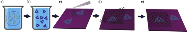
Figure 1. (a) and (b) Schematic representations of DNA origami synthesis; (c) DNA origami deposition; and (d) and (e) encapsulation by exfoliated graphene.
Download figure:
Standard image High-resolution image2.2. DNA origami deposition
After preparation, triangular DNA origami nanostructures were deposited onto ∼1 × 1 cm2 silicon substrates covered with 80 nm thick dry thermal oxide (SiO2/Si). Due to the interference of the light within the oxide layer, optical contrast of the graphene is enhanced and enables good visibility of graphene using optical microscopy, which is essential for the identification [47].
Before the deposition of DNA origami nanostructures, the substrates were cleaned and prepared by 5 min treatment in Novascan's ozone cleaner. Subsequently, drops of 0.5 μl of DNA origami solution were deposited on each substrate and covered with 10 μl of 10×TAE with 10 mM of MgCl2. After one hour of incubation period in the water-saturated environment, the samples were rinsed in 1:1 water-ethanol solution to clean excess of material and dried with an argon gun (flow ∼10 l min−1). As a result DNA origami nanostructures covered the entire substrates with an averaged density of twenty triangular nanostructures per square micrometer. The DNA origami deposition is schematically represented in figure 1(c).
2.3. Graphene exfoliation
Graphene was deposited using the procedure known as micromechanical cleavage [48], yielding high-quality layers of graphene but limited in lateral size (on the order of tens of micrometers in diameter). Kish graphite (Naturgraphite GmbH) was used as starting material. Graphite flakes were cleaved using sticky tape (Nitto Denko ELP BT150ECM) and deposited on the substrates with DNA origami nanostructures. In order to avoid damaging DNA origami nanostructures, the entire micromechanical exfoliation was carried out at room temperature. After the deposition of graphene on top of the DNA origami nanostructures, individual flakes were detected using optical microscopy and single atomic layer samples were chosen by the optical contrast, and confirmed by the AFM. Schematic representation of the encapsulation by graphene is shown in figures 1(d) and (e).
2.4. AFM measurements
AFM experiments were carried out on the NT-MDT's NTEGRA Prima system. Imaging before and after AFM manipulation was performed in tapping mode (TAFM), using NSG01 probes from NT-MDT (typical force constant 5.1 N m−1). AFM manipulation was done in contact mode, using NT-MDT's CSG01 probes (typical force constant 0.03 N m−1). All measurements were done at ambient conditions. Initial imaging of the samples was done in TAFM mode. In this mode, the vibrating AFM tip is free from a torsion, so it does not push DNA origami nanostructures laterally leaving them practically intact.
AFM manipulation of graphene has been done using both static [49, 50] and dynamic plowing [51]. Here, AFM manipulation experiments were done in the following way. After selected sample areas were found and visualized using TAFM mode, AFM manipulations were carried out in contact mode, by scanning a selected sample area. Every image was recorded at constant normal force (constant set point). Manipulation on the graphene encapsulated DNA origami nanostructures was carried out using TAFM (NGS01, force constant 5.1 N m−1). However, imaging of bare DNA nanostructures was not possible in contact mode with these hard cantilevers. For this reason the manipulation of bare nanostructures was done using soft CSG01 probes (with two order of magnitude lower force constant).
AFM topography images of the samples were processed in an open source software Gwyddion. For each image first a mean plane was subtracted, followed by line corrections in the scanning direction, and finally a three point plane leveling is applied and the mean height is set to zero value. In the cases of graphene/substrate step edges, the three points were chosen on the bare substrate.
3. Results and discussion
A typical TAFM topography image of a step edge of graphene, with (1.26 ± 0.21) nm height, covering a substrate with DNA origami nanostructures is shown in figure 2(a). In order to estimate the structural damage, both the height and the shapes of the triangular DNA origami nanostructures were considered. The shapes were straightforwardly assessed from the topography images. The height of the structures was determined using a peak-to-peak difference from the selected area histograms, as shown in figures 2(b) and (c). Each histogram peak was fitted by a single Gaussian line. The uncertainty of the measured height was estimated as a half width at half maximum of the histogram peak that corresponds to either bare or graphene encapsulated DNA origami nanostructures. As a result, an average height of the bare triangular DNA origami nanostructures was found to be (1.42 ± 0.38) nm, while the graphene encapsulated ones were (0.65 ± 0.24) nm high. The observed difference is due to non-perfect replication of DNA origami by graphene. Some parts of graphene covering DNA nanostructures do not lie perfectly on SiO2 substrate. These parts of graphene are slightly lifted above the substrate and make the effective height of the graphene covered DNA nanostructures smaller. This effect is even more pronounced for high density of deposited DNA origami nanostructures since graphene does not fall perfectly on  substrate between adjacent DNA nanostructures.
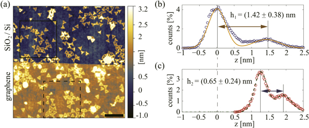
Figure 2. (a) TAFM topography of a step edge of graphene covering a substrate with DNA origami nanostructures. Scale bar is 500 nm. (b) and (c) histograms (circles) and Gaussian fits (solid and dashed lines) of the selected areas in (a), corresponding to the bare and graphene encapsulated nanostructures. h1 and h2 stand for the height of the bare and graphene encapsulated structures, and are estimated as a peak-to-peak distance within the corresponding histograms.
Download figure:
Standard image High-resolution image3.1. AFM manipulation
Imaging of DNA nanostructures in the contact mode is challenging [44]. Therefore, so far their mechanical properties and stability have been measured using peak force tapping mode with precisely controlled force in pico Newton range [52]. Here AFM manipulation in contact mode was applied in order to determine the forces required to damage both bare and graphene encapsulated DNA origami nanostructures. Figure 3 shows TAFM topography of DNA origami nanostructures before and after manipulation of a 500 × 500 nm2 selected area, marked by the dashed square. The selected area was repeatedly scanned six times in contact mode. The applied normal force was increased for each successive scan ranging from 36 to 76 nN. The contact mode topography scans are shown in figures 4(a)–(f). The same probe (NGS01) was used both for the imaging of the sample in TAFM mode and for the manipulation in contact mode. The height of the encapsulated nanostructures was estimated for each contact mode scan using their corresponding histogram peak-to-peak distance. The results are presented in figure 4(g), showing encapsulated structure height as a function of the applied normal force. Both the height and the shape of the triangular origami nanostructures indicate that structural damage starts to occur when a normal force of about 60 nN is exerted.
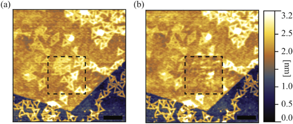
Figure 3. (a) A topography image (TAFM) of DNA origami nanostructures encapsulated by a single layer graphene (top) and on a bare SiO2/Si substrate (bottom). (b) The same sample area after scanning of the dashed square in contact mode with an applied force up to 76 nN. Scale bars are 250 nm.
Download figure:
Standard image High-resolution image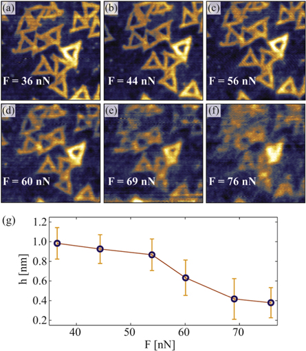
Figure 4. (a)–(f) 500 × 500 nm2 area of graphene encapsulated DNA origami nanostructures scanned in contact mode with an increase of the applied normal force (set point) for each successive image. The same sample area is also shown in figure 3, and highlighted with the dashed squares. (g) The height of graphene encapsulated DNA origami nanostructures shown in (a)–(f), with respect to the initial values.
Download figure:
Standard image High-resolution imageIn order to estimate the amount of mechanical protection that graphene offers to DNA origami nanostructures, the same AFM manipulation experiments are carried out on the bare triangular DNA origami nanostructures (on SiO2/Si substrate). Here much smaller normal forces are required to damage the structures. Thus, a soft mode probes (CSG01) were used, with the typical force constant of 0.03 N m−1. Figure 5 shows six subsequent scans in contact mode. Again, the normal force is increased for each scan, ranging from 1.8 to 3.1 nN. The triangular DNA origami nanostructures appeared unchanged up to the normal force of 2.5 nN.

Figure 5. (a)–(f) 1 × 1 μm2 area of bare DNA origami nanostructures on a SiO2/Si substrate scanned in contact mode. The applied force (set point) is increased for each successive image. Arrows in (d) indicate the initial damaged areas of the nanostructures, giving a force threshold of about 2.5 nN.
Download figure:
Standard image High-resolution imageThe nature of the structural damage that is introduced by the AFM probe is different for the bare and graphene encapsulated DNA origami nanostructures. In the case of the encapsulated nanostructures graphene protects them from attaching to the tip of the AFM probe. As a result, the damaged structures appeared "smudged" and their height is reduced. On the other hand the bare nanostructures tend to attach to the tip and drift in the scanning direction. As a result the height of the bare structures that were not pushed and damaged by the AFM probe does not change significantly (figure 5(f)).
The arrows in figure 5(d) indicate the initial damage of the bare DNA origami nanostructures, that is introduced with the normal force of only 2.7 nN. Compared with the same tests carried out on the encapsulated structures (figure 4), the force required to damage the DNA origami nanostructures is over an order of magnitude greater for the ones encapsulated with graphene. The structural damage that can be introduced by AFM manipulation strongly depends on the adhesion of both the DNA nanostructures and the graphene layer to the substrate. For this reason it is not reliable to set the exact force threshold at which graphene offers wear protection to these structures.
Still the question remains whether the cumulative damage arises when the same graphene encapsulated structures are scanned multiple times. To test this the same graphene encapsulated area was scanned in contact mode ten times successively. The normal force was set to 28 nN for all scans. TAFM topography images of the same sample area before and after manipulation are respectively shown in figures 6(a) and (b). Figure 6(c) shows the height of the graphene encapsulated DNA origami nanostructures for each TAFM and contact mode scan. The heights were obtained as a peak-to-peak distance from their corresponding topography images. The results show that there is no cumulative damage effect if the applied normal force is below the damage threshold (∼60 nN).
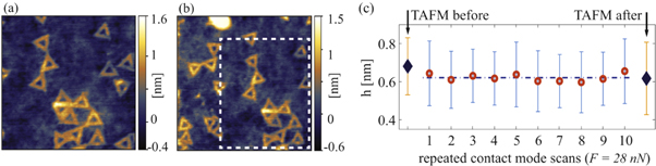
Figure 6. (a) 0.8 × 0.8 μm2 TAFM topography of graphene encapsulated DNA origami nanostructures prior to multiple scans in contact mode with low applied force (F = 28 nN). (b) 1 × 1 μm2 TAFM topography of the same sample area after ten successive scans in contact mode. The dashed square in (b) indicates the area scanned in contact mode. (c) The height of the graphene encapsulated DNA origami nanostructures after each step. Diamonds indicate TAFM measured height, while circles indicate the height measured in each contact mode scan.
Download figure:
Standard image High-resolution imageOn the other hand, only a single contact mode scan with high enough force is sufficient to damage graphene encapsulated nanostructures. This is demonstrated in figure 7. Here, TAFM topography images are shown before and after the selected area was scanned in contact mode with the normal force set to 188 nN, well above the damage threshold.
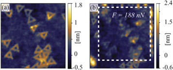
Figure 7. (a) 0.8 × 0.8 μm2 TAFM topography of graphene encapsulated DNA origami nanostructures prior to a single scan in contact mode with high applied force (F = 188 nN). (b) 1 × 1 μm2 TAFM topography of the same sample area after the scan in contact mode. The dashed square in (b) indicates the area scanned in contact mode.
Download figure:
Standard image High-resolution image3.2. Deionized water exposure
In order to extend the use of DNA origami nanostructures as scaffolds in the bottom-up nanofabrication [16], these structures need to be strong enough to withstand the harsh conditions needed in many fabrication steps [18]. Commonly these steps include submersion into liquids. Either as the part of the solution phase processing or simple rinsing after a lithography step, DNA origami nanostructures need to withstand both short and prolonged liquid exposures.
In this study the exposure to deionized water was tested on both bare and graphene encapsulated structures. The exposure time was varied between 1 min and 24 h. The SiO2/Si substrates covered with DNA origami nanostructures and partly encapsulated by graphene were submerged into 10 mL of DI H2O (Millipore, 18,2 MΩ cm−1) and after the set exposure time quickly dried with an argon gun (flow ∼10 l min−1). Water exposure was done successively on each flake, e.g.: the flake was exposed to 1 min in DI H2O, measured, then again exposed for 4 min more to give the total of 5 min exposure, and so on. This way properties that are unique for every sample, as adhesion of nanostructures and graphene to the substrate, did not figure in the test.
The selected sample areas were imaged using TAFM both prior and after DI H2O exposure. Figure 8 shows TAFM topography images of triangular DNA origami nanostructures partly encapsulated by graphene before exposure (a) and after various lengths of exposure to DI H2O (b)–(e).

Figure 8. (a) 3 × 3 μm2 TAFM topography images of an area of graphene encapsulated (right) and bare (left) DNA origami nanostructures, before (a) and after various lengths of exposure to DI H2O (b)–(e). Scale bars are 500 nm.
Download figure:
Standard image High-resolution image
The unprotected structures are significantly damaged even after only 1 min of DI H2O exposure, and not lifted-off the substrate. Most likely the amount of residual Mg2+ ions on the substrate surface determines whether the structures are damaged or lifted-off the substrate [18].
Graphene encapsulated DNA origami nanostructures appeared to be intact by the water exposure. Each individual triangular origami was preserved even after 30 min of DI H2O exposure. The height of the nanostructures was also unchanged. In the case of the sample shown in figures 8(a)–(d) the height of the encapsulated origami nanostructures was 0.8(±0.2) nm, after each exposure. In figure 8(d) the edge of graphene sample was folded, most likely during the drying step.
The only exception occurred after twenty four hours of exposure. In this case graphene started to wrinkle. Although some triangular DNA origami nanostructures are still visible underneath graphene (figure 8(f)), most of the nanostructures were damaged and their height estimation was not reliable.
The exact exposure time threshold will again depend on the adhesion to the substrate of both graphene and DNA origami nanostructures, and varies from sample to sample. Still, very short exposures do damage or lift-off bare DNA nanostructures [18]. On the other hand graphene encapsulation offers significant protection increasing the exposure times by at least two orders of magnitude.
4. Conclusion
In summary, we have demonstrated that single layer exfoliated graphene can be used as a protective layer for DNA origami nanostructures. Through the AFM based manipulation we have shown that the normal force required to damage graphene encapsulated DNA origami nanostructures is over an order of magnitude greater than for the unprotected ones. The threshold for the normal force that induces structural damage to the graphene encapsulated DNA origami nanostructures was found to be about 60 nN. In addition, we have shown that graphene provides wear protection against multiple manipulations if the applied normal force is below the damage threshold.
Besides wear protection, graphene encapsulated DNA origami nanostructures were tested against prolonged exposure to deionized water, and multiple immersions. We show that graphene encapsulated nanostructures remain intact even after 30 min of the exposure to deionized water, while the bare structures are significantly damaged in the matter of seconds. The limits of graphene protection against deionized water exposure arise from wrinkling of the graphene layer itself.
We expect that other liquids will act in the similar manner as long as they do not damage graphene, and will only take different amount of time to damage bare DNA origami nanostructures. This extends the use of DNA origami scaffolds in many fabrication processes, as various lithography steps or wet transfer of 2D materials. Future studies could involve encapsulation by more than one layer of graphene and the use of other 2D materials, as hexagonal boron nitride, which could prove protection in harsh environments that graphene might not be suitable for.
Acknowledgments
This work is supported by the Serbian MPNTR through Projects ON 171005, III 45018, IO 171020, 451-03-2802-IP/1/167, and by the DAAD bilateral project 451-03-01858/2013-09/1 between Republic of Serbia and Germany. BV acknowledges support from COST Action MP1303. IB acknowledges support from a Marie Curie FP7 Integration Grant within the 7th European Union Framework Programme, and by the Deutsche Forschungsgemeinschaft (DFG).