


Abstract
DEMO (DEMOnstration Fusion Power Plant) is a proposed nuclear fusion power plant that is intended to follow the ITER experimental reactor. The main goal of DEMO will be to demonstrate the possibility to produce electric energy from the fusion reaction. The injection of high energy neutral beams is one of the main tools to heat the plasma up to fusion conditions. A conceptual design of the Neutral Beam Injector (NBI) for the DEMO fusion reactor, is currently being developed by Consorzio RFX in collaboration with other European research institutes. High efficiency and low recirculating power, which are fundamental requirements for the success of DEMO, have been taken into special consideration for the DEMO NBI. Moreover, particular attention has been paid to the issues related to reliability, availability, maintainability and inspectability. A conceptual design of the beam source for the DEMO NBI is here presented featuring 20 sub-sources (two adjacent columns of 10 sub-sources each), following a modular design concept, with each sub-source featuring its radio frequency driver, capable of increasing the reliability and availability of the DEMO NBI. Copper grids with increasing size of the apertures have been adopted in the accelerator, with three main layouts of the apertures (circular apertures, slotted apertures and frame-like apertures for each sub-source). This design, permitting to significantly decrease the stripping losses in the accelerator without spoiling the beam optics, has been investigated with a self-consistent model able to study at the same time the magnetic field, the electrostatic field and the trajectory of the negative ions. Moreover, the status on the R&D carried out in Europe on the ion sources is presented.
Export citation and abstract BibTeX RIS

Original content from this work may be used under the terms of the Creative Commons Attribution 3.0 licence. Any further distribution of this work must maintain attribution to the author(s) and the title of the work, journal citation and DOI.
1. Introduction
The objectives of the nuclear fusion power plant DEMO, to be built after the ITER experimental reactor, are usually understood to lie somewhere between those of ITER and a 'first of a kind' commercial plant. In fact, while in ITER the goal is to demonstrate the possibility to obtain a plasma able to sustain the fusion nuclear reaction, in DEMO the main objective is to prove the industrial feasibility of fusion by showing the electricity production from the fusion reaction, the safety aspects and the Tritium self sufficiency. As a consequence, in DEMO the issues related to efficiency and reliability, availability, maintainability and inspectability (RAMI) are among to most important drivers for the design. In fact, the cost of the electricity produced by this power plant will strongly depend on these issues.
In the framework of the EUROfusion Work Package Heating and Current Drive (WPHCD) work programme within the Power Plant Physics and Technology (PPPT) activities, a conceptual design of the Neutral Beam Injector (NBI) for the DEMO fusion reactor [1–3] is currently being developed by Consorzio RFX in collaboration with other European research institutes and integrated into the DEMO1 reference design, as shown in figure 1.
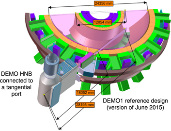
Figure 1. Integration of the Heating Neutral Beam in the DEMO1 pre-conceptual design.
Download figure:
Standard image High-resolution imageThe presented NBI conceptual design is proposed as a possible option for the usage in DEMO. Nevertheless, some of the design solutions here mentioned are still in the early R&D phase and their effective viability is to be demonstrated. This is particularly true for the photo-neutralization, for the non-evaporable getter (NEG) pumps and for the accelerator with increasing size and decreasing number of apertures as discussed in section 3. Hence, it should be considered as a wished 'Advanced DEMO NBI'. A design more similar to the ITER NBI (or 'ITER-like DEMO NBI') is also currently considered as a conservative option. In this case, the main NBI design solutions are closer to the ITER ones, i.e. a gas-neutralizer, a non-modular beam source and a standard accelerator with circular apertures for each grid. The definition of the final design will be based on the performance that will be obtained by the ITER NBI testbed (MITICA [4]), on the results of the R&D currently on-going regarding the negative ion beams and on the performances that will be shown by the ITER NBIs.
High efficiency and RAMI, which are fundamental requirements for the success of DEMO, have been taken into great consideration for the conceptual design of the DEMO NBI.
In the state-of-the-art negative ion based neutral beam injector (NNBI) under construction for ITER working at high energy (in the range of 1 MV), the beam source, the neutralizer and the beam duct were identified for efficiency improvements to gain for the needs of a high efficient NBI for a future DEMOnstration power plant. This paper focuses on the beam source. The requirements of the DEMO NBI are described in section 2. Then, the choice of the main operating parameters and the conceptual design are illustrated in section 3, with a particular focus on the improvements regarding efficiency and RAMI. Finally, the present status of the R&D on the ion sources and on the extraction/acceleration system is described in sections 4 and 5, respectively.
2. Definition of the demo NBI requirements
The main requirements of the DEMO NBI in comparison with the ITER NBI are reported in table 1. They were proposed by the working group on the DEMO NBI of Consorzio RFX, and discussed with the other research institutes and EUROfusion during several technical meetings in the period 2014–2016. These requirements refer to the case 'Advanced DEMO NBI', while the requirements for an 'ITER-like DEMO NBI' are identical to those of ITER, except for the duration of the beam on time (2 h instead of 1 h).
Table 1. Main requirements for the DEMO NBI, with a comparison to the ITER NBI. The DEMO NBI requirements refer to the case 'Advanced DEMO NBI', while the requirements for an 'ITER-like DEMO NBI' are the same of the ITER NBI ones, except for the duration of the Beam on time (2 h instead of 1 h).
| ITER NBI | Adv. DEMO NBI | |
|---|---|---|
| Species | H−/D− | D− |
| Beam energy (keV) | 1000 | 800 |
| Accelerated current (A) | 40 | 34 |
| Max. ion source filling pressure (Pa) | 0.3 | 0.2 |
| Beamlet divergence (mrad) | <7 | <7 |
| Beam on time (s) | 3600 | 7200 |
| Extracted e−/D− fraction | <1 | <1 |
| Neutralization efficiency | Not specifieda | >0.70 |
aThis value was not a requirement for ITER; it is foreseen to be about 0.55 for ITER.
It can be noted that the requirements of the advanced DEMO NBI are similar but not identical to the ones of the ITER NBI. Namely, it can be observed that:
- In the DEMO NBI, only deuterium negative ions are considered, whereas ITER NBI is also required to operate with hydrogen negative ions. A beam made of deuterium neutrals (D0) is the final goal also in both NBIs, but in ITER experiments with hydrogen neutrals (H0) are foreseen to test the system before the operations with D0.
- The beam energy requirement has been slightly decreased in the DEMO NBI compared to ITER (from 1 MeV to 800 keV) to improve the overall reliability of the NBI system integrated into the reactor, as discussed in section 3.
- The maximum ion source filling pressure has been decreased, to increase efficiency. In fact, the beam losses in the accelerator are strictly linked to the gas density in the accelerator, that in turn is proportional to the pressure in the ion source.
- The maximum divergence of the beamlets must be very small in both cases; this is required for an optimal optics of the neutral beam, allowing a large fraction of the particles to reach the plasma inside the main chamber.
- The required accelerated current has been decreased, to increase availability of the NBI at the required level of performance. This aspect is discussed in section 3.
- The extracted e−/D− fraction (or e−/H− fraction if the operations are with hydrogen ions) must be in both experiments kept lower than 1. A low ratio permits to limit the heat loads on the extraction grid (EG) and to increase the efficiency of the extraction/acceleration system, but can be obtained only with a good conditioning of the ion source [5].
- A neutralization efficiency higher than 0.7 has been introduced as a requirement of the DEMO NBI, because it is one of the main tools to decrease the recirculating power. On the other hand, neutralization efficiency is not a requirement for the ITER NBI.
- The beam-on time is doubled with respect to ITER (two hours instead of one hour), to cope with DEMO requirements in terms of long pulse (> 2 h) operations.
3. Implementation of efficiency and RAMI design guidelines
Considering the requirements above as a starting point, a large R&D effort is currently being applied in Europe to obtain for the main components of the DEMO NBI the maximum efficiency and the most effective system with respect to RAMI.
Efficiency is a fundamental aspect for the DEMO experiment because DEMO will be the first machine where electrical power will be produced and put in the net using the fusion reaction. The cost of the produced power will be strongly related to the overall efficiency of the plant, that in turn will be determined by the efficiency of the various subsystems. In this regard, the heating and current drive systems are particularly relevant subsystems, because they are foreseen to consume a significant amount of power, giving a large contribution to the amount of 'recirculating power' i.e. the power produced by the plant that must be used by the plant itself to maintain its operations. Hence, the efficiency of the NBI system is here considered as a basic guideline for the conceptual design because any increase in the efficiency implies a reduction of the recirculating power and as a consequence a decrease of the cost of the power produced by the experimental plant.
The primary purpose of the RAMI design approach is to make sure that all the systems of the DEMO machine will be reliable during the operation phase and maintain their performance under operational conditions with the best possible availability. Failure of only one small function might result in the machine being halted for long periods of time and result in high costs for repairs and replacements. It is therefore important that every system undergoes a technical risk analysis to evaluate what can go wrong, where and when, and to recommend spare components, back-up systems, increased frequency maintenance schedules, component standardization and systems design optimization to reduce the risk level of a main function breakdown to a minimum and to decrease the time to repair to a maximum.
The design of the DEMO NBI is currently in the conceptual design phase, hence at this stage it is possible to give only approximate evaluations on the efficiency of the various systems and to consider the RAMI approach only as a general guideline for the development of the design, without implementing a detailed and quantitative technical risk analysis of the various components. This will be possible in a later stage, during the engineering design phase. Nevertheless, efficiency and RAMI are considered fundamental for the project and have been preliminary considered from the beginning of the design activities, driving various design choices and R&D proposals as described in the following.
Based on the requirements described in section 2, a set of functional parameters was proposed by the design team and is reported in table 2, where also the main parameters of the ITER NBI are reported for comparison.
Table 2. Main parameters assumed for the advanced DEMO NBI, with a comparison to the ITER NBI.
| ITER NBI | Adv. DEMO NBI | |
|---|---|---|
| Extracted current density (A m−2) | 293 | 200 |
| Aperture radius (m) | 0.007 | 0.007 |
| Number of aperture columns per source | 20 | 4 |
| Number of aperture rows per source | 64 | 15 |
| Number of sub-sources | 1 | 20 |
| Total extraction area (m2) | 0.197 | 0.185 |
| Extracted current (A) | 57.7 | 36.9 |
| Acceleration voltage (kV) | 1000 | 800 |
| Auxiliaries/extraction overall efficiency | 0.9 | 0.9 |
| Gross power (MW) | 64.1 | 32.8 |
| Stripping/halo current losses efficiency | 0.7 | 0.9 |
| Accelerated current (A) | 40 | 33.3 |
| Beam source transmission efficiency | 0.95 | 0.98 |
| Neutralizer efficiency | 0.55 | 0.7 |
| Beam line/duct transmission efficiency | 0.8 | 0.92 |
| Power released to the plasma (MW) | 16.7 | 16.8 |
| Injector overall efficiency | 0.26 | 0.51 |
| Number of injectors | 3 | 3 |
| Overall NBI power to the plasma (MW) | 50.1 | 50.4 |
Comparing the ITER and DEMO values (ref. table 2), it can be noted that:
- The extracted current density assumed for the DEMO NBI is around 30% lower than the one of ITER. This choice is made to increase the reliability and availability of the overall system. In fact, the DEMO injectors must be operating with a higher reliability than the ITER ones and this can be generally obtained by working with lower values of extracted current density. Extracted current densities of deuterium negative ions around the values requested for ITER have been already demonstrated in the radio frequency (RF) ion sources of the Max-Planck-Institut für Plasmaphysik (IPP) of Garching in Germany [6], nevertheless the conditions for these results were optimal in terms of ion source conditioning and cesium distribution. On the other hand, the requirement on the maximum pressure inside the ion source is lower in DEMO NBI (0.2 Pa) than in ITER NBI (0.3 Pa): a decrease of the source pressure permits lower stripping losses in the accelerator (because the background gas density is everywhere lower) but poses also some limitations on the generation of negative ions and to the related extracted current. In fact, the extracted currents of negative ions and of co-extracted electrons are generally more stable with higher values of filling pressure in the ion source. Moreover, for DEMO it could be possible that a cesium-free operation will be considered more suitable (R&D is being carried out on this aspect) for its advantages in terms of reliability and control of the ion source. Cesium-free operations are giving at the moment significantly lower values of extracted ion current, but there are some encouraging results [7].
- The total acceleration voltage chosen for the DEMO NBI is 20% lower that the ITER one (800 kV compared to 1 MV). This design choice is also related to reliability issues. In fact, the voltage holding of 1 MV DC potential in presence of high magnetic fields can be obtained only with optimal conditions of the surfaces at different voltages, in terms of cleanliness and vacuum conditions [8]. Moreover, an 800 keV beam is foreseen to reduce the beam shine-through fraction in DEMO and enlarge the operational window.
- The beam source of the DEMO NBI is modular, with 20 sub-sources, each having its set of copper grid segment. The 20 grid segments of each grid will be supported by a common frame. On the other hand, the ITER beam source features a large single chamber. The number of apertures and total extraction area are similar in the two cases.
- The extracted current in the DEMO NBI is about 35% lower than the ITER NBI one, mainly as a consequence of the lower extracted current density.
- The gross power consumed by the NBI system, defined as (Extracted Current) * (Acceleration voltage) / (Auxiliaries/extraction overall efficiency7 ), is about 50% lower in DEMO, mainly because of the lower extracted current (∼30% less) and acceleration voltage (∼20% less).
- The stripping/halo current losses efficiency8 is higher in the DEMO NBI than ITER NBI. In fact, firstly the ion source in DEMO NBI is required to operate at lower pressure (0.2 Pa instead of 0.3 Pa), and secondly the accelerator is designed to increase pumping in the acceleration gaps, with an optimized design of the grids apertures and supporting frames. As a consequence, the background gas density and the stripping losses are foreseen to be significantly lower.
- The accelerated current, calculated as (Extracted Current) * (Stripping/halo current losses efficiency), is about 17% lower in DEMO than in ITER. The lower extracted current in DEMO is partially counterbalanced by the higher stripping/halo current losses efficiency.
- The beam source transmission efficiency9 is slightly larger in DEMO than in ITER NBI design, due to the fact that in DEMO NBI some grids have larger apertures (slot-like or frame-like) and the neutralizer is with a single gap instead of having four gaps in parallel like in ITER NBI. In this way, less beam is foreseen to be intercepted by the grids.
- The neutralizer efficiency10 assumed for DEMO NBI is larger than the one of ITER NBI (>0.70 compared to 0.55). This large improvement could be obtained adopting a photo-neutralizer, which is an encouraging alternative to the standard solution (gas neutralizer [9]) but is still to be tested. For this reason, a large R&D effort is currently on-going in Europe [10, 11].
- The beam line/duct transmission efficiency11 is also foreseen to be higher in DEMO than in ITER NBI (0.92 instead of 0.8). This ambitious goal could be obtained by generally decreasing the background gas density in the beam line vessel and in the duct. In the beam line vessel, gas density can be significantly reduced if the photo-neutralizer is adopted instead of gas neutralizer, because with gas neutralizer a relatively high density is required to obtain the optimal neutralization efficiency, and some gas will also flow from the neutralizer area to the other parts of the beam line vessel, inducing a relatively high distribution of background gas in the other regions of the beam line and imposing the adoption of a huge high vacuum pumping system in the order of thousands of m3 s−1. On the other hand, with a photo-neutralizer there is not a lower limit for gas density, hence a higher vacuum would be easily attainable, with a decrease of re-ionization losses in the region downstream of the neutralizer compared to the gas-neutralizer solution. In the duct, the gas density can be reduced with a high performance pumping system. Due to reliability, availability and safety reasons cryopumps are probably not able to operate in that region, but NEG pumps could be suitable (R&D is being carried out on this aspect [12]). With this pumping system, gas density and consequently stripping losses could be significantly decreased compared to the non-negligible values foreseen in the ITER NBI, where no pumping is foreseen in that region, due to physical limited space. Another possible solution, under development at Karlsruhe Institute of Technology (KIT) within the EUROfusion WPTFV (Work Package on Tritium Fuelling and Vacuum), is represented by the Mercury diffusion pumps [13].
- The power released to the plasma, calculated as (Acceleration voltage) * (Accelerated current) * (beam source transmission efficiency) * (Neutralizer efficiency) * (Beam line/duct transmission efficiency), is about the same in DEMO and ITER NBIs, around 16.8 MW per beam, permitting to inject in both cases around 50 MW in the tokamak plasma using three beams.
- The injector overall efficiency, calculated as (Power released to the plasma) / (Gross power), is about double in the DEMO NBI (around 0.51) than in the ITER one (around 0.26). This is mainly due to the higher efficiency of the neutralizer and to the lower amount of stripping (in the accelerator) and re-ionization (in the beam line vessel and in the duct) losses.
A conceptual design of the advanced DEMO NBI is shown in figure 2.

Figure 2. Overview of the DEMO NBI with the main components and a sketch of the grids of the modular extraction/acceleration system.
Download figure:
Standard image High-resolution imageThe main components are:
- A negative ion beam source, composed of 20 sub-sources (two adjacent columns of 10 sub-sources each).
- A photo-neutralizer based on the 'closed recirculating cavity with nonlinear gating' (RING) concept, using two lasers with 35 kW power and 1.5 μm wavelength (infrared). By means of a second harmonic generator, the 2nd harmonic remains trapped in the mirror system. More information on this can be found in [11]. The neutralizer structure includes a dedicated NEG-based pumping system (keeping a low background gas density in the region), an electron dump (dumping the electrons exiting from the accelerator together with the negative ions) and a neutron dump (dumping the neutrons coming form the main plasma in the tokamak chamber).
- A residual ion dump (RID) featuring a flat water cooled CuCrZr plate, supported from above by a stainless steel support structure that is connected to a dedicated upper flange. The CuCrZr plate has two vertical slits to let the beam pass through, while the residual ions are deflected by the stray magnetic fields onto the CuCrZr plate.
- A beam source vessel, containing the entire beam source with the related NEG pumps. The vessel has a large aperture on the right side to extract the entire beam source or the NEG pumps for possible inspection and maintenance.
- A beam line vessel, containing the complete neutralizer and RID structures. Both these two components are supported by the upper flange, hence they can be extracted from above.
- A duct connecting the beam line vessel to the tokamak chamber. The duct features a large NEG pump (to reduce gas density and re-ionization losses) and two heat dumps (to dump the heat loads by re-ionization).
A detail view of the extraction/acceleration system corresponding to a sub-source is shown on the left part of figure 2.
The dimension of each sub-source is approximately 0.4 × 0.4 × 0.4 m3. The total width and height of the sub-sources cluster is around 1 m and 4 m, respectively. Each sub-source features 4 × 15 apertures (4 in the horizontal direction, 15 in the vertical direction) with 20 mm horizontal step and 22 mm vertical step, like in the SPIDER [14] and MITICA [15] experiments. The ion beam is formed by two 'blades' with large height (about 4 m) and small width (about 70 mm). Each of these blades is formed by 10 sub-beams, one per sub-source. The blades are strongly convergent in the vertical direction, with a fan shape, to focus the entire beam to the opening in the blanket, where it enters in the main chamber.
From each sub-source, 4 × 15 beamlets are extracted. The total extracted current is (200 * π * 0.0072 * 4 * 15 * 20) A = 36.9 A, with the assumptions of:
- 200 A m−2extracted current of negative deuterium ions (D−). Anyway, the design of the extraction/acceleration system here presented would be also compatible with higher values of current densities, because a good optics condition with higher current can be obtained decreasing the extraction voltage, provided that the perveance
 , where I is the current extracted from the ion source and Vextr is the extraction voltage, remains constant.
 - PG with circular apertures (7 mm radius).
- 20 sub-sources and 4 × 15 beamlets extracted per sub-source.

The total power of the beam is calculated as 36.9 A * 800 kV * 0.9 * 0.98 * 0.7 * 0.92 = 16.8 MW (similar to the nominal power delivered by one of the ITER NBIs), with the assumptions of:
- 800 keV for the total energy of the beam.
- 0.9 for the stripping/halo current losses efficiency.
- 0.98 for the beam source transmission efficiency.
- 0.7 for the neutralizer efficiency.
- 0.92 for the beam line/duct transmission efficiency.
The modular solution for the beam source is found to have the following main advantages:
- A better alignment between the corresponding apertures of the grids, also in presence of thermal expansion, resulting in a better overall optics of the neutral beam. This is due to the fact that the modules have a significantly smaller size than the whole accelerator, hence the horizontal and vertical deformations are also reduced compared with a non-modular solution. In the ITER NBI, for instance, the modularity is only in the vertical direction (where there are four separated modules) but not on the horizontal one. This fact makes the alignment between the corresponding apertures of each grid quite difficult and a significant sensitivity of the aperture alignment to possible variations of grid temperature is present.
- A more uniform magnetic filter field inside each sub-source, because magnets and/or coils can be put among the two columns of sub-sources; magnetic filter field is a primary factor for the performance of negative ion source [5]. Moreover, a more uniform magnetic filter field could be an advantage considering the helicon ion sources described in par. 4, that are foreseen to work with a higher field (around 12 mT) than the classic IPP-type RF drivers.
- A good neutralization efficiency, considering the present choice of RING photo-neutralizer but also considering a gas neutralizer. In fact, with this modular solution two blade-like beams can be generated, which is the most convenient to limit the size of the neutralizer and increase its efficiency, and also to limit the gas throughput due to a relatively optimized neutralizer vacuum conductance.
- A higher availability during the operations in DEMO because if some sub-sources do not work properly, the remaining ones can in any case provide the negative ion beam, though with a lower value of total extracted current.
- The R&D phase can be carried out using a small beam source, which is more flexible and less expensive than a full size prototype. Once optimized, the sub-source can be replicated to form a cluster in the DEMO NBI.
On the other hand, there are also some drawbacks:
- A more complex construction of the ion sources, because there are 20 small ion sub- sources rather than a single large one. This also implies a more complex design of the high voltage bushing and of the electrical and cooling supplies.
- A more complex construction of the extraction/acceleration system, because the 20 grid segments composing each grid must be supported by a single frame structure that has to cope with high voltage and cooling issues.
4. R&D on innovative ion sources
The herewith conceptual design features for each sub-source a circular RF driver, designed following the research carried out by IPP Garching on the negative ion sources. Alternative concepts of the ion sources are being developed at IPP Garching in Germany and at the Swiss Plasma Center (SPC) in Switzerland.
To increase the RF efficiency and the operational reliability of the source it could be favorable to substitute two circular drivers by a single larger one. Potential advantages are that less power is needed for the same plasma density and dissociation degree, a simplified design and less problems with mutual inductance, which could occur with circular drivers placed close together. For this purpose a large driver with a race-track shaped base area is currently tested at IPP. As shown in figure 3, a six turn RF coil surrounds a 6 mm thick quartz insulator, which is mounted inside a vacuum chamber to avoid cracking by atmospheric pressure. An internal Faraday shield protects the quartz from plasma erosion. This source concept is used in the ASDEX Upgrade NBI for positive ions [16] and has proven its reliability for 19 years. Compared to two cylindrical drivers the larger volume of plasma generation results in an increased volume-to-surface ratio reducing the particle losses and the recombination surfaces. With the 'race-track driver', which is mounted onto an expansion volume, negative ion beam extraction experiments are currently carried out at IPP and the results are compared to the ones achieved with the previous source design.
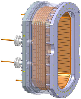
Figure 3. 3D drawing of the racetrack driver currently tested at IPP for negative ions. The walls of the vacuum chamber are shown transparent in the figure.
Download figure:
Standard image High-resolution imageAnother concept, which is pursued by IPP and SPC, is based on the use of helicon waves to generate the plasma. Since first experiments performed by Boswell [17], helicon sources have been extensively studied and proven to be very efficient for high-density (1018–1019 m−3), high ionization degree, plasma production with much higher power efficiency than standard inductively coupled plasma (ICP) generators. Helicon sources have found a wide range of applications, including semiconductor manufacturing and ion thruster systems for satellites. Recently, it has been proposed that helicon sources may be an interesting option for negative ions production for NBI systems for fusion [18]. In this context, helicon sources have the following advantages over traditional ICP generators: (1) reduced required RF power, leading to increase operational domain and lower recirculating power; (2) stable operation at low pressure (<1 Pa), reducing negative ion losses by electron stripping; (3) lower electron temperatures, resulting in higher efficiency of negative ion production; (4) high degree of molecular dissociation in hydrogen plasmas.
A lab scale experiment has been built up at IPP using a quartz tube with 10 cm diameter and 40 cm length. A standard ICP antenna can be exchanged by a helicon antenna (Nagoya type III) which favors together with an axial magnetic field the ∣m∣ = 1 helicon mode for propagation. Instead of aiming to operate in the full helicon mode for which several 100 mT are required, the investigations are focussed to achieve the better coupling due to the so-called low-field peak [19]. It has already been demonstrated that the low-field peak appears below 10 mT in hydrogen and deuterium plasmas at the relevant source pressure, showing that in the peak a higher dissociation degrees and plasma densities are achieved [20]. Further studies concentrate on the dependence on the RF frequency and source diameter to optimize the system.
A 10 kW, helicon plasma generator based on a resonant antenna [21] for the Cybele source [10] has been developed at the SPC [22] in collaboration with CEA-Cadarache. This helicon source is an intermediate step towards larger radio-frequency powers, which will allow investigating the main technology and physics issues related to high power helicons, including comparisons with standard helicon antennas, in a well diagnosed and controlled laboratory setup. A picture of the resonant antenna is shown in figure 4. The antenna diameter is 13cm to fit with the Cybele source and the 15 cm long conducting parts are made of copper tubing to allow water cooling of the system. The capacitors are made of parallel arrangements of 6 high Q (quality factor) mica capacitors. The total individual capacitance of each arrangement (C = 3840 pF) was chosen to obtain a resonance of the antenna at 13.56 MHz. The cooling of the RF antenna is ensured by water circulation. Two semi-cylindrical metallic screens are disposed around the antenna. The adjustment of the screens position allows the antenna resonant frequency to be tuned with 2 MHz accuracy. First tests of the resonant antenna performance were done on the resonant antenna ion device at SPC. These include tests with hydrogen and deuterium gas at different pressures, magnetic field and RF power levels, spectroscopic measurements of the H2/D2 dissociation rate and Langmuir probe measurements of electron density and temperature profiles. Stable operation in both hydrogen and deuterium are obtained for the working nominal conditions required in the Cybele source, namely 0.3 Pa of pressure and approximately 12 mT of magnetic field. Measurements using compensated Langmuir probes and absolutely calibrated emission spectroscopy, indicate the presence of negative hydrogen/deuterium ions and a dissociation degree increasing with injected RF power. This result is promising in view to adopt and to assess the performances of a resonant helicon antenna for the negative ion sources in future NBI applications.
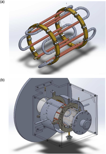
Figure 4. Helicon plasma sources: (a) drawing of the resonant antenna with main elements: capacitors assemblies, copper rods, and cooling water circuit; (b) installation of the antenna on the end flange of the RAID device; the two semi-cylindrical metallic screens allow fine tuning of the resonant frequency.
Download figure:
Standard image High-resolution image5. R&D on innovative concepts of extraction/acceleration systems
The proposed conceptual design of the extraction/acceleration system for the DEMO NBI, sketched in figure 2, features six grids:
- A plasma grid (PG).
- An EG.
- Three acceleration grids (AG1, AG2 and AG3).
- A grounded grid (GG).
Each RF sub-source has its dedicated set of segments. This modular solution permits to obtain better beam optics than using large grid segments with many beamlet groups. Consequently, each of the six grids is divided into 20 grid segments, with external dimensions of approximately 350 × 350 mm2. For each grid, a frame maintain each grid segment in the correct position. Vertically, the apertures cover the whole dimension of the grid segment, while horizontally the apertures are only located in the central part. This permits to generate a couple of blade-like beams, that have the required width of 70 mm, as required by the characteristics of the photo-neutralizer. In any case, this layout also permits an optimized design of the gas neutralizer, if this is the chosen option.
The grid thicknesses are kept equal to MITICA and ITER NBI: 9 mm for the PG and 17 mm for EG, AG1, AG2, AG3 and GG [15]. The same is valid for the gaps between the grids, that are of 6 mm between PG and EG, and of 88 mm in all the other cases, being 88 mm a trade-off between reasons related to optics and high voltage insulation. Finally, also the shapes of the apertures on the first three grids (PG, EG and AG1) are identical to the optimized ones in MITICA and the magnetic configuration of the EG.
The main differences with MITICA are the number of the grids (6 instead of 7) and the shape/number of apertures. In fact, for each sub-source the apertures shapes are 60 circular for PG, EG and AG1 (15 rows with 4 apertures each), 15 slotted for AG2 and 1 frame-like for AG3 and GG, as visible in figure 2. The slotted grid concept has been derived by the work carried out at NIFS [23], while the frame-like apertures were inspired by the SINGAP concept [24].
It can be noted that, moving from the ion source to the accelerator exit, the apertures are strongly increased in size and decreasing in number. This approach permits to obtain at the same time good optics and good efficiency of the accelerator. In fact, the optics of the beam is mostly depending on the shape of the first three grids (PG, EG and AG1). Here, a good quality is provided by a large number of apertures with optimized shape. On the other hand, the density of the background gas can be significantly decreased if the vacuum pumping inside the accelerator is enhanced. This effect can be obtained by increasing the size and decreasing the number of the apertures in the last grids (AG2, AG3 and GG). If the gas density decreases inside the accelerator, also the amount of negative ions that are neutralized by stripping reactions decreases, hence the efficiency of the accelerator is increased. An estimate of the efficiency improvement compared to the MITICA case is planned in the next future using the AVOCADO code [25].
5.1. First analyses on the DEMO NBI extraction/acceleration system
To optimize the design of DEMO NBI extraction/acceleration system, a self-consistent model of the DEMO NBI grids has been developed in the COMSOL environment, able to investigate the magnetic, the electrostatic and the particle tracking aspects at the same time. In this model, each beamlet is composed by 1000 macro-particles, starting from a meniscus pre-calculated with the SLACCAD code [26], analogously to the SPIDER [14] and MITICA [15] cases. The particles are deflected by the magnetic and electric fields at the same time, being the electric field calculated summing the field generated by the grids plus the contribution due the negative space charge of the particles. The model, shown in figure 5, includes all the grids, with circular apertures in the first three grids, slotted apertures in the AG2 and frame-like apertures in the AG3 and GG. As a consequence, the electrostatic lenses have a different shape in the different grids. For reasons of calculation time, a 4 × 6 matrix of apertures has been considered instead of the complete 4 × 15 matrix shown in the design of figure 2 and corresponding to a sub-source. Nevertheless, this domain permits to study all the main electrostatic effects (focusing/defocusing given by the electrostatic lenses, mutual repulsion among beamlets) and magnetic effects (deflection by the permanent magnets embedded in the grids).
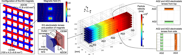
Figure 5. Overview of the self-consistent electrostatic-magnetic-particle tracking model of the DEMO NBI accelerator. The model includes all the grids, with circular apertures in the first three grids, slotted apertures in the AG2 and frame-like apertures in the AG3 and GG. As a consequence, the electrostatic lenses have a different shape in the different grids. The EG features two sets of permanent magnets: CESM (co-extracted electron suppression magnets) and ADCM (asymmetric deflection compensation magnets, to compensate for the alternate deflection of the negative ions generated by the CESM).
Download figure:
Standard image High-resolution imageThe criss-cross deflection effect (CCDE) appears in many multi-aperture negative ion accelerators, causing an unwanted worsening of the beam optics. This effect is generated by the residual alternate deflection of the negative ions due to the magnets that are usually embedded in the EG to suppress the co-extracted electrons. These magnets, here called co-extracted electron suppression magnets (CESMs), are alternately polarized along the beam direction and are located horizontally between the EG aperture rows, as shown in figure 5. In this way, they are effective in suppressing the co-extracted electrons by deflecting them onto the EG itself, but they also deflect the negative ions so that a remaining horizontal deflection is generally observed at the accelerator exit, as visible for example in the 'no ADCM' case of figure 6 (the ADCM are explained below). As this deflection is alternated from an aperture row to the other, a typical zigzag pattern is observed on the beam footprint [27]. Due to this effect, in DEMO NBI a remaining deflection of about 3 mrad is expected (+3 mrad for the even beamlets and −3 mrad for the odd ones). This problem is particularly detrimental if the beam is to be injected into a plasma chamber located at a large distance from the NBI, like it is in ITER and DEMO. In this case, if the beam is not well focused, a significant part of it will impinge on the beam line components or on the duct instead of reaching the plasma inside the main chamber, leading to a decrease of the NBI overall efficiency.
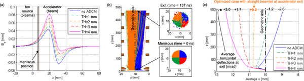
Figure 6. Main results of the single beamlet simulation: (a) magnetic field profile along the aperture axis with different values of the ADCM thickness; (b) particle trajectories in the case with no ADCM (the particles from the four quarters of the meniscus have a different color so that the deflection effect is more visible); (c) particle average trajectory with different values of the ADCM thickness. It can be observed that the case with an ADCM thickness of 2 mm provides an almost perfect compensation of the CCDE.
Download figure:
Standard image High-resolution imageThe CCDE can be compensated for by applying a suitable electrical field by means of a steering grid, located at the downstream surface of the EG [28].
An alternative approach to compensate for this effect, proposed by RFX [29], is to add another set of magnets called asymmetric deflection compensation magnets (ADCMs) in the EG, placed vertically beside each aperture of the EG and having a polarization along the vertical direction, as shown in the left part of figure 5. The main effect of these magnets is that they amplify the magnetic field by CESM on the upstream side of the EG, while decreasing it on the downstream side, as visible in figure 6(a). This approach was found to have significant advantages compared to the electrostatic compensation:
- It is expected to work properly with a large range of accelerator energy, because a magnetic deflection is compensated by an additional magnetic field. On the other hand, if a magnetic deflection is compensated by an additional electric field, the compensation effect is working properly only for one operating scenario (i.e. one value of the accelerator potential).
- It is adjustable by changing the ADCM dimensions or degree of magnetization.
- It is more compatible with long pulses.
Due to these advantages, a solution with the ADCM has been chosen for the MITICA accelerator [15] and is also proposed here for the DEMO NBI.
The thickness of the ADCM, indicated as 'TH' in figure 5 must be optimized in order to obtain a null alternated deflection (zero CCDE) at the accelerator exit. Both the CESM and ADCM are assumed to have a magnetic remanence of 1.1 T. This is a typical value for Sm2Co17, that was chosen as the reference material for the magnets because of its stability at high temperature (up to 250 °C).
To find a first reasonable value of the ADCM thickness, a single beamlet model was used (shown in figure 6), where also the last three grids are assumed with a circular aperture shape, identical to AG1. First of all, the optics of the beamlet was roughly optimized acting on the potential of the EG. Assuming an extracted current density of negative deuterium ions of 200 A m−2, a reasonable optics of the beamlet was obtained with the following potentials for the six grids (from PG to GG): 0, 8.6, 200, 400, 600 and 800 kV.
Then, the CCDE was calculated considering 5 different values of the ADCM thickness (TH in figure 5). Each case gives a different profile of the vertical magnetic field By as shown in figure 6(a). The peaks are simmetric with no ADCM, while the upstream peak height is increasingly higher (in absolute value) and the downstream peak height is increasingly lower when the ADCM thickness is increased.
As an example of the CCDE, figure 6(b) shows the trajectories of the 1000 considered particles in the case with no ADCM. The beamlet is firstly deflected leftwards and then rightward, with a visible residual rightward deflection at the accelerator exit. This residual deflection of the beamlet is of about 2.6 mrad rightward as shown in the 'no ADCM' case of figure 6(c). This figure also reports the residual beamlet deflections when the ADCM are included in the model. In particular, it can be observed that an almost perfect compensation of the CCDE can be obtained using ADCM with 2 mm thickness. On the other hand, a partial compensation is obtained with lower thickness values (1 mm thick ADCM) and an over-compensation with higher values (3 and 4 mm thick ADCM). Hence, the optimal 2 mm thickness for the ADCM is also implemented in the full model with 4 × 6 apertures.
Figure 7 reports the main results of the full model with 4 × 6 apertures:
- As visible in figure 7(a), the beamlets are subjected to the effect of the repulsion due to space charge plus the CCDE.
- The CCDE can be compensated with the ADCM. In fact, comparing figure 7(b) (without ADCM) and (c) (with 2 mm thick ADCM), it can be observed that adding the ADCM significantly reduces the CCDE. This can be seen by the fact that the deflections of row 3 (red numbers) and of row 4 (blue number) are quite similar (in the same column) in the case with ADCM (figure 7(c)) while they their difference is larger in the case without ADCM (figure 7(b)).
- As the accelerator is quite long, the repulsion effect is in this case stronger than CCDE. The effect of the repulsion can be reduced using kerbs located on the downstream side of the grids, analogously to MITICA [15], as shown in figure 7(d).
- A strong defocusing lens is generated at the GG, because for this grid there is electrical field only at the upstream side. The defocusing effect can be reduced by enlarging the width of the GG aperture. This improvement can be appreciated comparing figure 7(d), having the standard width of the GG aperture (76 mm), with figure 7(e), having an increased width of the GG aperture (156 mm). For all the other aspects, the two cases are identical. It can be observed that, while in figure 7(d) the beamlets still have significant deflections (in the outward direction) at the accelerator exit, in figure 7(e) they are almost parallel the beam axis at the accelerator exit, with a maximum deflection of only 4.8 mrad. However, there is still margin for further improvements that will be investigated in the next future.

Figure 7. Main result of the full model with 4 × 6 apertures: (a) trajectories seen from downstream, where the effect of the repulsion among beamlets and CCDE can be clearly observed (here, the case without ADCM is considered); (b) beamlet trajectories without ADCM; the horizontal residual deflections at the exit (reported for beamlet rows 3 and 4) are influenced by the repulsion among beamlets plus CCDE; (c) beamlet trajectories with 2 mm thick ADCM; CCDE is significantly reduced; (d) beamlet trajectories with 2 mm thick ADCM and kerbs; repulsion effect is reduced (e) beamlet trajectories with 2 mm thick ADCM, kerbs and enlarged GG aperture; repulsion effect is almost completely compensated, as the eight beamlets are now almost parallel to the beam axis at the accelerator exit. The main electrostatic lenses are plotted in green.
Download figure:
Standard image High-resolution image
6. Conclusions
A conceptual design of the DEMO NBI has been developed by Consorzio RFX in collaboration with other research institutes. This conceptual design features a modular approach for the ion source and for the extraction/acceleration system, and accelerator grids with increasing size and decreasing number of apertures. These modifications in contrast to the ITER reference design are aimed at increasing efficiency (or lowering the recirculating power) and better coping with the RAMI design approach.
The main components of the DEMO NBI have been drafted, based on the present knowledge and on the R&D currently being carried out in various research institutes. The design of most components will be further developed and discussed within EUROfusion and with the other involved research institutes in the next future. In particular, the possible usage of the race-track drivers or helicon plasma source concepts, here summarized, have been investigated.
Several analyses have been carried out to assess and optimize this conceptual design study for a future DEMO NBI. In particular, a self consistent magnetic-electrostatic-particle tracking model has been build and used as the main tool for the development of the extraction/acceleration system for the DEMO NBI. The first results show that the conceptual design with the decreasing number of apertures (slotted apertures in the AG2, frame-like apertures in the last two grids) could be a viable option by the beam optics point of view.
The various concepts under development, after demonstrating their feasibility and performances in the different facility throughout Europe, could be tested in the next future using the ITER-like and DEMO-like experiments (in terms of size, power and energy) hosted in the neutral beam test facility PRIMA.
Acknowledgments
This work has been carried out within the framework of the EUROfusion Consortium and has received funding from the Euratom research and training programme 2014-2018 under grant agreement No 633053. The views and opinions expressed herein do not necessarily reflect those of the European Commission.
Footnotes
- 7
The auxiliaries/extraction overall efficiency is the total power absorbed by the accelerator divided by the total power consumption of the accelerator power supplies plus the auxiliaries of the NBI system.
- 8
The stripping/halo current losses efficiency is the ion beam power at the exit of the accelerator divided by the theoretical ion beam power without stripping losses and interception of halo on the grids.
- 9
The beam source transmission efficiency is the ion beam power at the entrance of the neutralizer divided by the ion beam power at the exit of the accelerator.
- 10
The neutralizer efficiency is the neutral beam power at the exit of the neutralizer divided by the ion beam power at the entrance of the neutralizer.
- 11
The beam line/duct transmission efficiency is the neutral beam power reaching the main chamber divided by the neutral beam power at the exit of the neutralizer.