


Abstract
The effect of spin–rotation coupling is measured for the first time with neutrons. The coupling of spin with the angular velocity of a rotating spin turner can be observed as a phase shift in a neutron polarimeter set-up. After the neutron's spin is rotated by 2π through a rotating magnetic field, different phase shifts are induced for 'up' and 'down' spin eigenstates. This phase difference results in the rotation of the neutron's spin-vector, which turns out to depend solely on the frequency of the rotation of the magnetic field. The experimental results agree well with the solutions acquired by the Pauli–Schrödinger equation.

Content from this work may be used under the terms of the Creative Commons Attribution 3.0 licence. Any further distribution of this work must maintain attribution to the author(s) and the title of the work, journal citation and DOI.
1. Introduction
All experiments in stationary laboratories are actually performed in accelerated systems which can lead to lots of significant phenomena. An example of uniform acceleration is given by gravitation while Coriolis, centrifugal, or Euler forces inevitably appear as consequences of circular motion. In the beginning of the 20th century another discovery of the effects induced by acceleration was made, i.e., a phase shift of light in a rotating ring interferometer. This is known as the Sagnac effect, which was originally predicted and measured for light [1] and is nowadays utilized in laser and fiber-optic gyroscopes. The Sagnac effect is induced by the interaction between the orbital angular momentum of the beam in the interferometer and the rotation of the experimental apparatus relative to the rest frame. Experiments with matter–wave interferometers with neutrons [2, 3] and atoms [4, 5] also confirmed the Sagnac effect in the quantum regime.


Neutron optics play a crucial role in the investigation of quantum physical effects and is established as an indispensable tool to gain insight in a wide spectrum of quantum phenomena exploiting quantum interference [6, 7]. Since the 1970s neutron interferometry has made essential contributions to the measurement of important effects like the wave nature of massive particles [8], the 4π-symmetry of fermions [9, 10], the spin-superposition principle [11, 12], and, more recently, intra-particle entanglement [13, 14]. In neutron interferometry the consequences of rotation and gravitational interaction appear as a change of the phase of the neutron's wave function determined by the respective potential. This has been demonstrated by measurements showing the influence of Earth's gravitation [15], Earth's rotation [2, 16], or the motional effect on the wave function (Fizeau effect) [17]. Nowadays new methods have been established for investigation of effects that appear to observers in non-inertial frames of reference such as nuclear spin gyroscopes [18, 19] and atom interferometry [20–22].
Remarkable experiments have likewise been made with neutron polarimetry. The rich functionality and advantages of the polarimetry method can be found in various measurements, such as that of the Berry phase [23, 24], the Aharonov–Bohm effect [25, 26], and the validation of the non-commutativity [27] of Pauli spin operators. Most recently the study of a new error-disturbance relation [28, 29] with neutron polarimetry has been performed [30, 31]. Neutron polarimetry exhibits quantum interference between orthogonal spin eigenstates with matter-waves. Circumstances with high phase stability can be realized with much larger spaces for installing optical elements compared to neutron interferometry. These conditions enable tests of fundamental phenomena in quantum mechanics with neutron matter-waves.
2. Spin–rotation coupling in neutron-polarimetry
Since the discovery of spin of elemental particles in the last century the understanding of rotations in quantum physics had to be expanded algebraically by an intrinsic form of angular momentum. For spin-1/2 particles a unitary transformation between the quantum system of a static and a rotating reference frame is given by , where is the total angular momentum of a system. The sum of orbital and spin contributions yields the spin–rotation coupling, described by the interaction term [32, 33]. This is analogous to the 'Sagnac term', where is again the angular velocity of the apparatus and is the spin angular momentum operator of the particle, respectively. This interaction was recently derived by Hehl and Ni [34] in the non-relativistic limit of the Dirac equation for a Minkowski frame that is both rotating and linearly accelerating. For zero proper acceleration they derived the following Hamiltonian


Further theoretical analysis [35–41] established a solid foundation for the spin–rotation coupling mathematically.
To confirm the spin–rotation coupling experimentally a measurement in a neutron interferometer set-up was proposed [42] (more details given in section 4). Unfortunately, neutron interferometry encounters some difficulties. The major disadvantages stem from the high sensitivity to ambient, i.e., thermal, disturbances mainly from spin flippers and the limited size available in the neutron interferometer. We will now describe why a spatial separation of the trajectories is irrelevant to measure the phase shift. Instead, a superposition of 'up' and 'down' spin states can be used to reveal the relative phase shift between the spin eigenstates as a change of the spin polarization. The adaptation to a neutron polarimeter set-up is depicted in figure 1.

Figure 1. Actual neutron polarimeter set-up with a total length of roughly 3 m. Blue and red arrows indicate spin states. Polarizing supermirror (P); guide field (GF); rotating spin turner (RST); static spin turner (SST); analyzing supermirror (A); detector (D). The GF is compensated inside the RST and SST.
Download figure:
Standard image High-resolution imageTo describe the interaction of the spin of a free neutron in a magnetic field with angular velocity Ω the Pauli–Schrödinger equation is solved. For a particle propagating in direction in a uniformly rotating magnetic field of the type the equation reads


The Pauli equation in a rotating magnetic field for plane waves is analytically solvable [43] and in this particular case given by

where generates the rotation of the initial spin state ,


The square of the magnitude of the rotation vector is given by a Pythagorean equation


where we used the definition of the Larmor frequency . The solution equation (4) contains the coupling term and describes the evolution of the spin states for both the rotating and the static field () Instead of a flip it is better to choose a multiple of 2π in which case the dynamical part becomes disengaged from the spinor function and the phase shift can be attributed purely to a geometric phase.


If we prepare the incident beam to be the effect of the spin–rotation coupling can be seen when we choose to represent the initial state as a superposition of and states. The outcome of the spinor function in this set-up after a time t1 and a rotation changes according to (4) in the following form


We observe that the spin–rotation coupling gives a positive phase shift for the neutron-spin polarized parallel to the axis of rotation and a negative phase shift for the anti-parallel spin state. According to the evolution of the spin-state the neutron's polarization vector changes, where consists of the Pauli matrices. The relative phase difference of the superposed spin-states changes after the rotating spin turner (RST) from the initial polarization vector to


The calculation predicts that the polarization vector after a 2π rotation is pointing in a direction in the xz-plane depending on the angular velocity of the exterior magnetic field. It is worth noting here that in the adiabatic case this phase shift can again be argued in terms of a geometric phase [44].

For higher precision and feasibility it is more convenient to keep Ω constant and scan a relative phase, just like in an interferometer experiment with a phase shifter. For that purpose a static spin turner (SST) was employed in the set-up. The distance between the coils was chosen such that the precession after the RST yields a rotation of , and the polarization vector after a time t2 turns from the xz-plane into the yz-plane. When the neutrons enter the SST, the polarization vector is rotated around the x-axis by varying the static magnetic field B3. The task of the rotation angle is to scan for the phase shift previously induced in the RST. The final polarization vector after the SST attains a form analogous to equation (8), i.e.,


which corresponds to the intensity

The coupling term can be deduced by observing the phase shift at the intensity maximum (or any other significant point), which for the interval is obviously given by


3. Measurements
The neutron polarimeter experiment was carried out at the 250-kW TRIGA MARK II reactor in Vienna. The incident monochromatized neutrons have a wavelength of Å ( 2000 ms−1) and are polarized in the first supermirror (P). A guide field (GF) determines the quantization axis and screens the RST and SST of the set-up from ambient magnetic fields. Within the RST and SST the GF is compensated. The action of the RST is expressed by two unitary transformations as shown in equation (4). The right transformation describes a rotation around the direction . Since we choose the action of the unitary transformation is given by . The second unitary transformation is the action responsible for the spin–rotation coupling. The SST is a special case of the RST with . In the SST a rotation of the neutron spin is induced around a static axis by an angle and is commonly referred to as Larmor precession. The ratio of the change rate of the magnetic field's direction Ω to the Larmor frequency determines the response of the spin to the exterior magnetic field in the RST. When the change of the magnetic field's direction is very slow in comparison to the Larmor frequency then the spin will follow the magnetic field adiabatically. Otherwise the spin transport is given by the precession around the axis of rotation .


The length of the rotating field coil was chosen to be 20 cm. The rotating magnetic field is generated by two sinusoidal signals with a relative phasing of 90 deg. For compensation of the GF an offset current in one solenoid coil is applied. Furthermore, the Larmor frequency and rotation frequency of the magnetic field Ω in the RST are of the same order with equality at 7 kHz. Therefore the spin-transport in the RST (and in the entire set-up) is non-adiabatic. According to equation (5) for a rotation angle of and a time of flight the frequency can take values between 0–10 kHz. For these frequencies no electric resonant circuit is needed and the observable phase shift amounts to per ν =1 kHz. A major point of our adjustment concerned the correct tuning of the amplitude B0. Since a rotation in the RST is required the corresponding pair of values () has to be chosen according to equation (5). This condition was confirmed by observing the preservation of the contrasts for each frequency, since the contrasts of the intensity oscillations decrease for inappropriately adjusted amplitudes of the rotating magnetic field. Therefore B0 was determined by fixing the angular velocity Ω and searching for the maximum of the intensity at the point of the expected phase shift.


Figure 2 shows the result of four oscillations of the normed neutron intensity as a function of the rotation angle and exhibits the correct phase shift according to equation (10) for ν = 0 , 3 , 6 , and 9 kHz. For Ω = 0 kHz no phase shift is observed and the oscillogram shows the behaviour of a SST, while the sinusoidal intensity modulation shifts to the left for increasing frequencies. The intensity modulations were measured by applying 12 different frequencies, and kHz. The observed phase shift is plotted in figure 3 (A) as a function of the frequency ν. A linear behaviour is clearly seen, as theoretically expected. Except for 8 kHz and 9 kHz all results are within the error bounds of the expected values predicted by the Pauli–Schrödinger equation. The slight deviation of approx. 1.5 deg for the two highest frequencies comes from the reduction of the magnetic field B0, making these points more susceptible to ambient field disturbances. The errors that have been taken into account are the statistical deviations of the measured points as well as the accuracy and reproducibility of the entire set-up. Other potential sources of errors (e.g., the length of the coil, the distance between the coils, and the monochromaticity of the beam) could be neglected. In figure 3(B) the contrast C of the intensity modulations is plotted as a function of the applied frequencies ν. The average contrast achieved is 95.23(84)%.


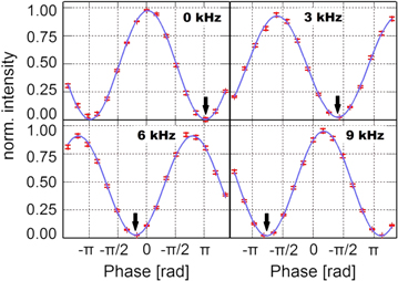
Figure 2. Shift of the periodic signal depending on the frequency. The minimum is marked with a bold black arrow to guide the eye. Each point has been measured for 2 min. The count rate at the intensity maximum is ≈ 4500 neutrons min−1.
Download figure:
Standard image High-resolution image
Figure 3. (A) Observed phase shift together with the theoretically predicted dependence. (B) Contrast corresponding to each measured intensity oscillation. The average contrast achieved is C = 95.23(84)%.

Download figure:
Standard image High-resolution image4. Discussions and outlook for neutron interferometry
Originally, the spin–rotation coupling was expected to be a small perturbation in addition to the Sagnac effect in rotating (neutron-) interferometer experiments; assuming for example that spin 'up' and 'down' eigenstates propagate each in one arm parallel (antiparallel) to the interferometer's axis of rotation , the spin–rotation coupling yields an additional energy shift [45] of . Unfortunately the typical order of magnitude of the spin–rotation coupling in comparison to the Sagnac effect is predicted to be proportional to the de-Broglie wavelength (Angstrom) divided by the circumference of the interferometer [32] (of order cm), which is of order , hence essentially not accessible.


By using light as an example Mashhoon et al [42] argued that in a rotating optical interferometer with right circularly polarized (RCP) light in one arm and left circularly polarized (LCP) light in the second arm a phase shift, depending on the interferometer's angular velocity, should occur in the same way that a frequency shift appears when the helicity of circular polarized light passing through a rotating half-wave plate (HWP) is inverted. The latter has been observed in a series of measurements [46–48].
A scheme of a proposed measurement for spin 1/2-particles is shown in figure 4. Polarized neutrons initially propagating in direction are split into two arms of an interferometer of which one contains a static spin flipper (SSF) and the other one a rotating spin flipper (RSF) whose angular velocity vector is parallel to the initial neutron spin. The first proposals of the experiment suggested the use of a mechanically rotating coil, analogous to the HWP in the optical interferometer scheme, but it was pointed out later [45] that this situation is physically equivalent to a static quadrature coil producing a rotating magnetic field .


Figure 4. Concept of a neutron interferometer equivalent to the experiment proposed in [45]. Blue and red arrows indicate initial and flipped spin states. Static spin flipper (SSF); rotating spin flipper (RSF); phase shifter (PS); detectors (O)(H).
Download figure:
Standard image High-resolution imageWe will show here that the interferometer configuration leads to the same results as the polarimeter. Generally the wave function in the interferometer can be written as

where the parameter χ is the phase between paths I and II. Setting and calculations show that interference fringes will exhibit a shift after the recombination of the sub-beams analogous to equation (10), i.e.,


An easy way to double the contribution of the phase shift is to replace the SSF in the interferometer with a RSF rotating in opposite direction (), which would make the spins flip clockwise and counter-clockwise, respectively.

Now observe that for . Assume we have spins with opposite directions interacting with equally clockwise rotating magnetic fields, i.e., the angular velocity vectors are parallel to each other, but the spin is polarized 'up' in one path of the interferometer and 'down' in the other one. Instead of interference fringes we can observe the change of the neutron's polarization vector , where consists of the Pauli matrices. The relative phase difference of the superposed spin-states yields the same result as equation (9) (except that x and y entries are interchanged)


In the original proposal of the configuration [32] the interaction appeared purely as a phase shift as described by the SU(2) group. The change of the polarization vector (described by O(3)-group) is induced by the change of potential energy in one of the sub-beams. Yet, this situation can also be realized in a single beam trajectory by using a superposition of 'up' and 'down' spin states, where one spin is flipped clockwise and vice versa. With and we get


Equation (14) reproduces the situation of the polarimeter and concludes our demonstration of the equivalence of the set-ups.
5. Conclusions
A neutron-polarimeter experiment to measure the spin–rotation coupling suggested by Mashhoon has been carried out. This measurement is analogous with the interferometric set-up that has been proposed. We have realized a polarimeter experiment where the phase shift due to spin–rotation coupling is observed as the fringe shift of the interferogram between two spin eigenstates. It has been shown that the interaction is responsible for the phase shift of that occurs for spinors polarized parallel (+) or anti-parallel to the axis of rotation. The use of the polarimeter overcomes the difficulties of the interferometric measurement. The production of the rotating field in a longer coil enabled us to increase the observable phase shift and showed the advantage of this set-up. We mention that an analogous polarimeter set-up could measure the helicity–rotation coupling of photons for coherently superposed RCP and LCP waves. The obtained results agree well the with theoretical prediction. Moreover, the final average contrast of 95.23(84)% confirms the high reliability of our measurement.


Acknowledgments
This work was financed by the Austrian Science Fund (FWF) Project Nos. P25795-N20 and P24973-N20.